2012 CHEVROLET TAHOE roof
[x] Cancel search: roofPage 9 of 60

Black plate (3,1)Chevrolet Tahoe Police and Special Service Packages - 2012
Seats and Restraints 3-3
Notices for Customer
Installed Equipment
Read the following notices before
installing equipment on your
specialty vehicle.
Notice:GM-approved service
procedures must be followed to
remove and reinstall the
instrument panel to the pad in
order to ensure proper airbag
deployment. Notice:
Do not mount equipment
on the passenger side of the
instrument panel top pad
deployment zone. Equipment
should not be mounted on or
around the passenger airbag
opening because of a deploying
airbag. To allow the airbag to
perform as it was designed, do
not mount equipment inside the
airbag deployment zone.
Notice: The police vehicle has
roof-rail airbags. Do not mount a
security barrier such that the
ends of the barrier or brackets
are within the roof-rail
deployment zones. Notice:
The police vehicle has
roof-rail airbags and a rollover
sensor. The rollover sensor is
mounted on the centerline of the
vehicle between the driver and
right front passenger positions.
If the vehicle has bucket seats,
the rollover sensor will be
exposed. Do not mount
equipment within 25 mm (1 in) of
the rollover sensor. This may
affect the performance of the
airbag system. To allow the
airbags to perform as they are
designed, do not mount
equipment near this area.
Notice: Avoid installing wiring for
roof-rail emergency lighting or
radio antennas that may restrict
the proper deployment of the
roof-rail airbags.
Page 12 of 60

Black plate (6,1)Chevrolet Tahoe Police and Special Service Packages - 2012
3-6 Seats and Restraints
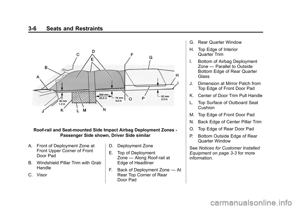
Roof-rail and Seat‐mounted Side Impact Airbag Deployment Zones -Passenger Side shown, Driver Side similar
A. Front of Deployment Zone at Front Upper Corner of Front
Door Pad
B. Windshield Pillar Trim with Grab Handle
C. Visor D. Deployment Zone
E. Top of Deployment
Zone —Along Roof-rail at
Edge of Headliner
F. Back of Deployment Zone —At
Rear Top Corner of Rear
Door Pad G. Rear Quarter Window
H. Top Edge of Interior
Quarter Trim
I. Bottom of Airbag Deployment Zone —Parallel to Outside
Bottom Edge of Rear Quarter
Glass
J. Dimension at Mirror Patch from Top Edge of Front Door Pad
K. Center of Door Trim Pull Handle
L. Top Surface of Outboard Seat Cushion
M. Top Edge of Front Door Pad
N. Back Edge of Center Pillar Trim
O. Top Edge of Rear Door Pad
P. Bottom Outside Edge of Rear Quarter Window
See Notices for Customer Installed
Equipment on page 3‑3 for more
information.
Page 13 of 60

Black plate (7,1)Chevrolet Tahoe Police and Special Service Packages - 2012
Seats and Restraints 3-7
Roof-rail and Seat‐mounted Side Impact Airbag Driver and PassengerDeployment Zones - View from Rear Cargo Area
A. Roof-rail Airbag Deployment Zone
B. Underside of Headliner
C. Edge of Headliner
D. Inner Center Pillar Trim E. Bottom of Door Windows
F. Front Seat Headrest
G. Seat Centerline
H. Inner Door PadI. Seat‐mounted Side Impact
Airbag deployment
Zone —Front Seat
J. Top Surface of Outboard Front Seat Cushion
See Notices for Customer Installed
Equipment on page 3‑3 for more
information.
Page 22 of 60

Black plate (2,1)Chevrolet Tahoe Police and Special Service Packages - 2012
9-2 Driving and Operating
The following guidelines can help
you with proper loading and load
distribution when installing
additional equipment on the Tahoe
Police Package.
{WARNING
Do not load the vehicle any
heavier than the Gross
Vehicle Weight Rating
(GVWR), or either the
maximum front or rear Gross
Axle Weight Rating (GAWR).
This can cause systems to
break and change the way the
vehicle handles. This could
cause loss of control and a
crash. Overloading can also
shorten the life of the vehicle. Adding Equipment to Your
Vehicle
Before adding accessories or
equipment to your police vehicle,
there are some things you need
to know:
.The police vehicle's maximum
capacity weight.
.The weight of your police
vehicle, including a full tank of
fuel but without a driver and
passengers.
.The weight of items you plan on
adding to your police vehicle,
like roof mounted light bar(s),
push bumpers, security
barrier(s), rear storage
organizer, highway flares, fire
extinguishers, weapons,
ammunition, radios, and video
equipment.
.The weight and number of
passengers you intend to carry
in your vehicle.
.The total weight of any
additional cargo you intend to
carry in your vehicle.
When planning your vehicle
equipment installation remember not
to exceed the Gross Vehicle Weight
Rating (GVWR) or the Gross Axle
Weight Rating (GAWR) of the front
or rear axles. To keep the available
load weight less than the vehicle
capacity weight, you may need to
limit the number of passengers you
carry in your vehicle or change your
choice of additional equipment.
Page 24 of 60

Black plate (4,1)Chevrolet Tahoe Police and Special Service Packages - 2012
9-4 Driving and Operating
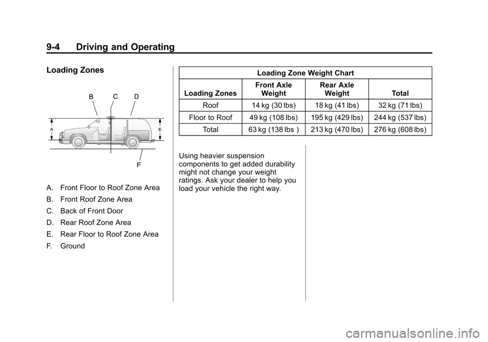
Loading Zones
A. Front Floor to Roof Zone Area
B. Front Roof Zone Area
C. Back of Front Door
D. Rear Roof Zone Area
E. Rear Floor to Roof Zone Area
F. GroundLoading Zone Weight Chart
Loading Zones Front Axle
Weight Rear Axle
Weight Total
Roof 14 kg (30 lbs) 18 kg (41 lbs) 32 kg (71 lbs)
Floor to Roof 49 kg (108 lbs) 195 kg (429 lbs) 244 kg (537 lbs) Total 63 kg (138 lbs ) 213 kg (470 lbs) 276 kg (608 lbs)
Using heavier suspension
components to get added durability
might not change your weight
ratings. Ask your dealer to help you
load your vehicle the right way.
Page 31 of 60

Black plate (1,1)Chevrolet Tahoe Police and Special Service Packages - 2012
Special Equipment Options 15-1
Special Equipment
Options
SEO Standard Options
SEO StandardOptions - Police Package
and Special Service
Package . . . . . . . . . . . . . . . . . . . 15-2
Wiring Provisions for 12-Volt Battery Power Supply . . . . . . 15-2
Auxiliary Battery Power Junction Blocks . . . . . . . . . . . . 15-8
Equipment Grounding Studs - Rear
Compartment . . . . . . . . . . . . . 15-10
Radio Suppression Grounding Straps . . . . . . . . . 15-10
SEO Available Options
Dual BatterySystem - SEO 6A6 . . . . . . . . 15-10
Exterior Lamp Emergency Flashing
System - SEO 6J7 . . . . . . . . 15-11
Inactive Rear Door Handles - SEO 6B2 . . . . . . . 15-14
Inactive Rear Door Locks - SEO 6N6 . . . . . . . . . 15-14
Inactive Rear Door Windows - SEO 6N5 . . . . . . 15-14
Spotlamp - SEO 7X6 . . . . . . . 15-14
Spotlamps - SEO 7X7 . . . . . . 15-14 Wiring Provisions for
Emergency Vehicle Roof
Light - SEO TRW . . . . . . . . . 15-15
Wiring Provisions for Horn/ Siren Circuit - SEO 6J4 . . . 15-20
Wiring Provisions for Vehicle Grille Lamps, Flasher, and
Speaker/
Siren - SEO 6J3 . . . . . . . . . . 15-22
Wiring Provisions Front Speakers - SEO WX7 . . . . . 15-24
Page 45 of 60

Black plate (15,1)Chevrolet Tahoe Police and Special Service Packages - 2012
Special Equipment Options 15-15
Wiring Provisions for
Emergency Vehicle Roof
Light - SEO TRW
Battery power is supplied through a
30 amp fuse to a wiring harness
located in the roof. Power is
controlled with a switch located in
the overhead console. The
customer or vehicle upfitter must
complete the installation to an
added accessory such as an
emergency beacon lamp.
Maximum rated electrical load is
21 amps (250 watts). The added
electrical requirements must not
exceed 21 amps (250 watts).
Running the accessory for long
periods of time with the engine off
may run the battery down.Installation
Instructions
–Emergency
Vehicle Roof Panel Lamp
Wiring to the accessory can be
done by either directly connecting
the wire in the roof to the accessory
(Option A) or by using Wiring
Harness Package part number
12150250 obtained from GM
Service Parts (Option B).
A. 645 mm (25.39 in)
B. 440 mm (17.32 in)
C. 100 mm (3.94 in) square D. Roof Centerline
E. Roof Edge
1. Disconnect the negative (−)
battery cable at the battery.
2. Make the electrical connections using either option A or option B.
Notice: Pulling the wiring
harness through a panel hole that
has sharp edges may cause
damage to the wire and/or wire
insulation. Remove sharp edges
from the panel hole before pulling
the wire through it.
Option A: Roof Wires Directly to
Accessory
1. Drill a 10 to 13 mm (3/8 in to 1/2 in) hole in the outer roof
panel in the area shown in the
illustration. The hole should only
go through the outer panel.
Remove all sharp edges from
the drilled hole.
2. Remove the inside overhead console access panel/lamp
lenses.
Page 46 of 60

Black plate (16,1)Chevrolet Tahoe Police and Special Service Packages - 2012
15-16 Special Equipment Options
3. The accessory harness is coiltied to the passenger side of the
vehicle at the console inner
bracket.
4. Cut the tape holding the harness coil.
5. As one person watches the roof hole from the outside for the end
of the harness, a second person
from the inside of the vehicle
should snake the harness
toward the hole.
6. Pull out the wiring harness being careful to avoid scraping the
insulation on the edge of
the hole.
7. Extend the wiring harness to the accessory. 8. Connect the dark green wire to
the accessory hot terminal.
9. Connect the black wire to the accessory ground terminal.
10. Cover the hole in the roof with a durable sealant such as
silicone rubber sealer.
11. Reinstall the overhead console access panel/lamp lenses.
Option B: Use Wiring Harness
Package 12150250. Obtain from
GM Service Parts through the GM
Dealership
1. Drill a 32 mm (1.25 in) hole in the outer roof panel in the area
shown in the illustration. The
hole should only go through the
outer panel. Remove all sharp
edges from the drilled hole.
2. Remove the inside overhead console access panel/lamp
lenses. 3. The accessory harness is coil
tied to the passenger side of the
vehicle at the console inner
bracket.
4. Cut the tape holding the harness coil.
5. As one person watches the roof hole from the outside for the end
of the harness, a second person
from the inside of the vehicle
should snake the harness
toward the hole.
6. Pull out the wiring harness being careful to avoid scraping the
insulation on the edge of
the hole.
7. Cut the wire to length. Install terminals to wire ends and insert
into the connector. The dark
green wire goes to cavity A and
the black wire in cavity B. Push
in the secondary lock to retain
the wires.