2012 CHEVROLET ORLANDO spare wheel
[x] Cancel search: spare wheelPage 301 of 378
Black plate (67,1)Chevrolet Orlando Owner Manual - 2012
Vehicle Care 10-67
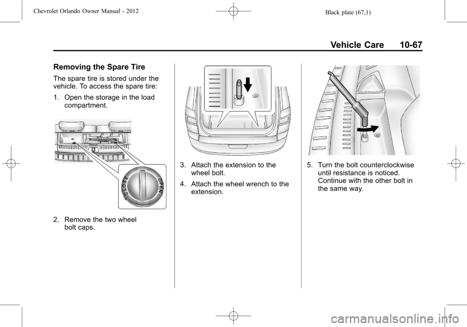
Removing the Spare Tire
The spare tire is stored under the
vehicle. To access the spare tire:
1. Open the storage in the loadcompartment.
2. Remove the two wheelbolt caps.
3. Attach the extension to thewheel bolt.
4. Attach the wheel wrench to the extension.5. Turn the bolt counterclockwiseuntil resistance is noticed.
Continue with the other bolt in
the same way.
Page 302 of 378
Black plate (68,1)Chevrolet Orlando Owner Manual - 2012
10-68 Vehicle Care
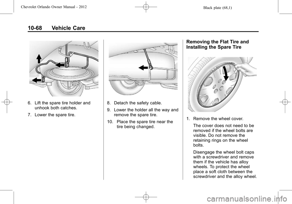
6. Lift the spare tire holder andunhook both catches.
7. Lower the spare tire.8. Detach the safety cable.
9. Lower the holder all the way and remove the spare tire.
10. Place the spare tire near the tire being changed.
Removing the Flat Tire and
Installing the Spare Tire
1. Remove the wheel cover.
The cover does not need to be
removed if the wheel bolts are
visible. Do not remove the
retaining rings on the wheel
bolts.
Disengage the wheel bolt caps
with a screwdriver and remove
them if the vehicle has alloy
wheels. To protect the wheel
place a soft cloth between the
screwdriver and the alloy wheel.
Page 303 of 378
Black plate (69,1)Chevrolet Orlando Owner Manual - 2012
Vehicle Care 10-69
After removing the wheel cover, use
the following instructions to remove
the flat tire and install the spare tire.
1. Do a safety check beforeproceeding. See If a Tire Goes
Flat on page 10‑56 for more
information.
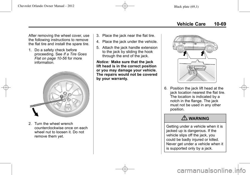
2. Turn the wheel wrench counterclockwise once on each
wheel nut to loosen it. Do not
remove them yet. 3. Place the jack near the flat tire.
4. Place the jack under the vehicle.
5. Attach the jack handle extension
to the jack by sliding the hook
through the end of the jack.
Notice: Make sure that the jack
lift head is in the correct position
or you may damage your vehicle.
The repairs would not be covered
by your warranty.
6. Position the jack lift head at the jack location nearest the flat tire.
The location is indicated by a
notch in the flange. The jack
must not be used in any other
position.
{WARNING
Getting under a vehicle when it is
jacked up is dangerous. If the
vehicle slips off the jack, you
could be badly injured or killed.
Never get under a vehicle when it
is supported only by a jack.
Page 305 of 378
Black plate (71,1)Chevrolet Orlando Owner Manual - 2012
Vehicle Care 10-71
WARNING (Continued)
an emergency, a cloth or a paper
towel can be used; however, use
a scraper or wire brush later to
remove all rust or dirt.
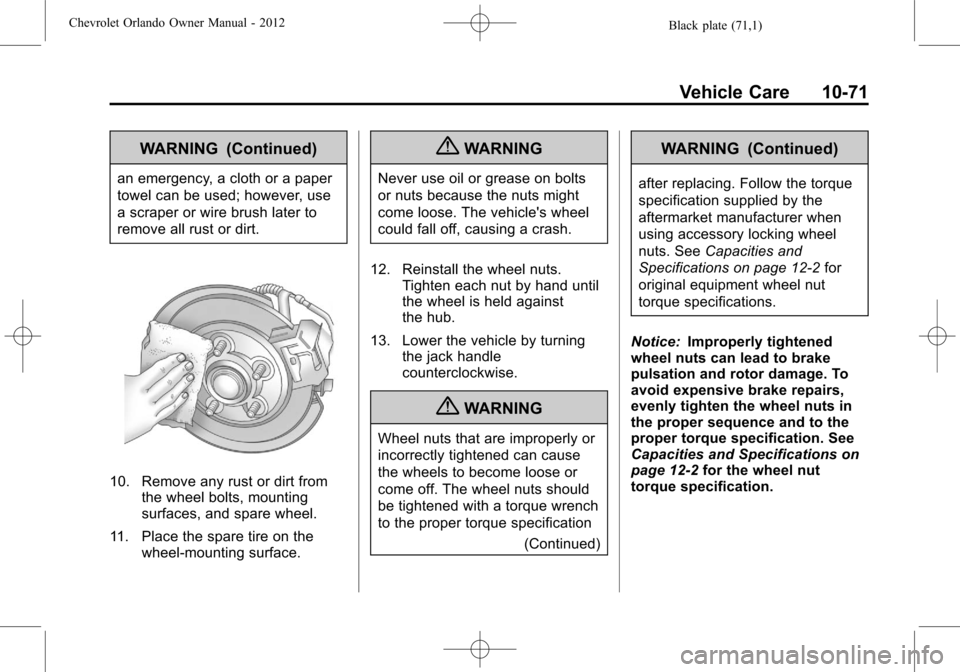
10. Remove any rust or dirt fromthe wheel bolts, mounting
surfaces, and spare wheel.
11. Place the spare tire on the wheel-mounting surface.
{WARNING
Never use oil or grease on bolts
or nuts because the nuts might
come loose. The vehicle's wheel
could fall off, causing a crash.
12. Reinstall the wheel nuts. Tighten each nut by hand until
the wheel is held against
the hub.
13. Lower the vehicle by turning the jack handle
counterclockwise.
{WARNING
Wheel nuts that are improperly or
incorrectly tightened can cause
the wheels to become loose or
come off. The wheel nuts should
be tightened with a torque wrench
to the proper torque specification
(Continued)
WARNING (Continued)
after replacing. Follow the torque
specification supplied by the
aftermarket manufacturer when
using accessory locking wheel
nuts. SeeCapacities and
Specifications on page 12‑2 for
original equipment wheel nut
torque specifications.
Notice: Improperly tightened
wheel nuts can lead to brake
pulsation and rotor damage. To
avoid expensive brake repairs,
evenly tighten the wheel nuts in
the proper sequence and to the
proper torque specification. See
Capacities and Specifications on
page 12‑2 for the wheel nut
torque specification.
Page 306 of 378
Black plate (72,1)Chevrolet Orlando Owner Manual - 2012
10-72 Vehicle Care
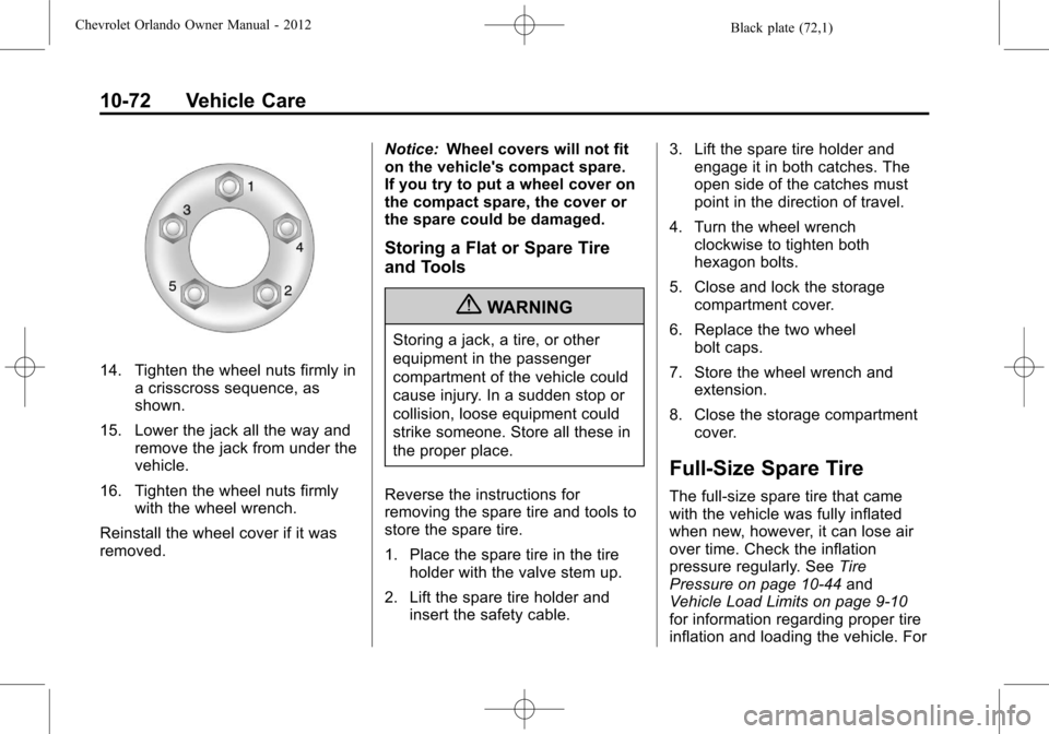
14. Tighten the wheel nuts firmly ina crisscross sequence, as
shown.
15. Lower the jack all the way and remove the jack from under the
vehicle.
16. Tighten the wheel nuts firmly with the wheel wrench.
Reinstall the wheel cover if it was
removed. Notice:
Wheel covers will not fit
on the vehicle's compact spare.
If you try to put a wheel cover on
the compact spare, the cover or
the spare could be damaged.
Storing a Flat or Spare Tire
and Tools
{WARNING
Storing a jack, a tire, or other
equipment in the passenger
compartment of the vehicle could
cause injury. In a sudden stop or
collision, loose equipment could
strike someone. Store all these in
the proper place.
Reverse the instructions for
removing the spare tire and tools to
store the spare tire.
1. Place the spare tire in the tire holder with the valve stem up.
2. Lift the spare tire holder and insert the safety cable. 3. Lift the spare tire holder and
engage it in both catches. The
open side of the catches must
point in the direction of travel.
4. Turn the wheel wrench clockwise to tighten both
hexagon bolts.
5. Close and lock the storage compartment cover.
6. Replace the two wheel bolt caps.
7. Store the wheel wrench and extension.
8. Close the storage compartment cover.
Full-Size Spare Tire
The full-size spare tire that came
with the vehicle was fully inflated
when new, however, it can lose air
over time. Check the inflation
pressure regularly. See Tire
Pressure on page 10‑44 and
Vehicle Load Limits on page 9‑10
for information regarding proper tire
inflation and loading the vehicle. For
Page 307 of 378
Black plate (73,1)Chevrolet Orlando Owner Manual - 2012
Vehicle Care 10-73
instructions on how to remove,
install, or store a spare tire, seeTire
Changing on page 10‑66.
After installing the spare tire on the
vehicle, stop as soon as possible
and check that the spare is correctly
inflated. The spare tire is made to
perform well at speeds up to
112 km/h (70 mph) at the
recommended inflation pressure, so
you can finish your trip.
Have the damaged or flat road tire
repaired or replaced and installed
back onto the vehicle as soon as
possible so the spare tire will be
available in case it is needed again.
Do not mix tires and wheels of
different sizes, because they will not
fit. Keep the spare tire and its wheel
together.Jump Starting
For more information about the
vehicle battery, see Battery on
page 10‑21.
If the battery has run down, try to
use another vehicle and some
jumper cables to start your vehicle.
Be sure to use the following steps to
do it safely.
{WARNING
Batteries can hurt you. They can
be dangerous because:
.They contain acid that can
burn you.
.They contain gas that can
explode or ignite.
.They contain enough
electricity to burn you.
If you do not follow these steps
exactly, some or all of these
things can hurt you. Notice:
Ignoring these steps
could result in costly damage to
the vehicle that would not be
covered by the warranty.
Trying to start the vehicle by
pushing or pulling it will not
work, and it could damage the
vehicle.
The jump start positive post is
located in the engine compartment
on the driver side of the vehicle.
See Engine Compartment Overview
on page 10‑6.
The jump start negative grounding
point is the engine block or an
engine mounting bolt. Connect to a
spot as far away from the
discharged battery as possible.
These locations are used instead of
a direct connection to the battery.
Page 376 of 378

Black plate (10,1)Chevrolet Orlando Owner Manual - 2012
i-10 INDEX
Service (cont'd)Parts Identification Label . . . . . 12-1
Publications Ordering
Information . . . . . . . . . . . . . . . . .13-11
Scheduling Appointments . . . . . 13-7
Vehicle Messages . . . . . . . . . . . . 5-30
Vehicle Soon Light . . . . . . . . . . . . 5-15
Servicing the Airbag . . . . . . . . . . . 3-31
Shift Lock Control Function Check, Automatic
Transmission . . . . . . . . . . . . . . . . 10-23
Shifting Into Park . . . . . . . . . . . . . . . . . . . . . . 9-19
Out of Park . . . . . . . . . . . . . . . . . . . 9-20
Sidemarker and Stoplamps Bulb Replacement . . . . . . . . . . 10-27
Signals, Turn and Lane-Change . . . . . . . . . . . . . . . . . 6-4
Specifications and Capacities . . . . . . . . . . . . . . . . . . . . 12-2
Speedometer . . . . . . . . . . . . . . . . . . 5-10
StabiliTrak OFF Light . . . . . . . . . . . . . . . . . . . . . 5-18
System . . . . . . . . . . . . . . . . . . . . . . . 9-31
Start Vehicle, Remote . . . . . . . . . . 2-5 Starter Switch Check . . . . . . . . . 10-22
Starting the Engine . . . . . . . . . . . . 9-17
Starting the Vehicle
Messsages . . . . . . . . . . . . . . . . . . . 5-30
Steering . . . . . . . . . . . . . . . . . . . . . . . . 9-3 Power, Warning Lights . . . . . . . . 5-17
Wheel Adjustment . . . . . . . . . . . . . 5-2
Wheel Controls . . . . . . . . . . . . . . . . 5-3
Storage Areas Cargo Cover . . . . . . . . . . . . . . . . . . . 4-2
Cargo Management System . . . 4-4
Center Console . . . . . . . . . . . . . . . . 4-2
Convenience Net . . . . . . . . . . . . . . 4-5
Front . . . . . . . . . . . . . . . . . . . . . . . . . . 4-1
Glove Box . . . . . . . . . . . . . . . . . . . . . 4-1
Instrument Panel . . . . . . . . . . . . . . 4-1
Roof Rack System . . . . . . . . . . . . . 4-5
Storing the Tire Sealant and Compressor Kit . . . . . . . . . 10-65
Stuck Vehicle . . . . . . . . . . . . . . . . . . . 9-9
Sun Visors . . . . . . . . . . . . . . . . . . . . . 2-17
Sunroof . . . . . . . . . . . . . . . . . . . . . . . . 2-17
Symbols . . . . . . . . . . . . . . . . . . . . . . . . . . iv
System Infotainment . . . . . . . . . . . . . . . . . . . 7-1
Roof Rack . . . . . . . . . . . . . . . . . . . . . 4-5T
Tachometer . . . . . . . . . . . . . . . . . . . . 5-10
Taillamps
Bulb Replacement . . . . . . . . . . 10-27
Text Telephone (TTY) Users . . . 13-4
Theft-Deterrent Systems . . . . . . . 2-10 Immobilizer . . . . . . . . . . . . . . . . . . . 2-10
Third-Row Seats . . . . . . . . . . . . . . . 3-12
Time . . . . . . . . . . . . . . . . . . . . . . . . . . . . 5-5
Tires Buying New Tires . . . . . . . . . . . 10-51
Chains . . . . . . . . . . . . . . . . . . . . . . 10-56
Changing . . . . . . . . . . . . . . . . . . . 10-66
Designations . . . . . . . . . . . . . . . 10-40
Different Size . . . . . . . . . . . . . . . 10-52
Full-Size Spare . . . . . . . . . . . . . 10-72
If a Tire Goes Flat . . . . . . . . . . 10-56
Inflation Monitor System . . . . 10-46
Inspection . . . . . . . . . . . . . . . . . . 10-49
Messages . . . . . . . . . . . . . . . . . . . . 5-31
Pressure Light . . . . . . . . . . . . . . . . 5-18
Pressure Monitor System . . . 10-45
Rotation . . . . . . . . . . . . . . . . . . . . 10-49
Sealant andCompressor Kit . . . . . . . . . . . 10-58