2012 CHEVROLET MALIBU window
[x] Cancel search: windowPage 213 of 398
Black plate (21,1)Chevrolet Malibu Owner Manual - 2012
Driving and Operating 9-21
Retained Accessory
Power (RAP)
These vehicle accessories can be
used for up to 10 minutes after the
engine is turned off:
.Audio System
.Power Windows
.Heated Seats (if equipped)
.Sunroof (if equipped)
These features continue to work up
to 10 minutes after the ignition is
turned to LOCK/OFF.
The power windows, heated seats,
and sunroof will work until any door
is opened.
The radio continues to work until
the driver door is opened.
All these features operate when
the key is in the ON/RUN or
ACC/ACCESSORY.
Shifting Into Park
{WARNING
It can be dangerous to get out of
the vehicle if the shift lever is not
fully in P (Park) with the parking
brake firmly set. The vehicle can
roll. If you have left the engine
running, the vehicle can move
suddenly. You or others could be
injured. To be sure the vehicle will
not move, even when you are on
fairly level ground, use the steps
that follow. If you are pulling a
trailer, see Driving Characteristics
and Towing Tips on page 9‑42. 1. Hold the brake pedal down
and set the parking brake.
See Parking Brake on page 9‑29
for more information.
2. Move the shift lever into P (Park) by holding in the button on the
shift lever and pushing the shift
lever all the way toward the front
of the vehicle.
3. Turn the ignition key to LOCK/OFF.
4. Remove the key and take it with you. If you can leave the vehicle
with the ignition key in your
hand, the vehicle is in P (Park).
Page 215 of 398
Black plate (23,1)Chevrolet Malibu Owner Manual - 2012
Driving and Operating 9-23
To shift out of P (Park):
1. Apply the brake pedal.
2. Press the shift lever button.
3. Move the shift lever to thedesired position.
If still unable to shift out of P (Park):
1. Fully release the shift lever button.
2. Hold the brake pedal down and press the shift lever
button again.
3. Move the shift lever to the desired position.
If you are still having a problem
shifting, see your dealer.
Parking over Things
That Burn
{WARNING
Things that can burn could touch
hot exhaust parts under the
vehicle and ignite. Do not park
over papers, leaves, dry grass,
or other things that can burn.
Engine Exhaust
{WARNING
Engine exhaust contains carbon
monoxide (CO) which cannot be
seen or smelled. Exposure to CO
can cause unconsciousness and
even death.
Exhaust may enter the vehicle if:
.The vehicle idles in areas
with poor ventilation (parking
garages, tunnels, deep snow
that may block underbody
airflow or tail pipes).
.The exhaust smells or
sounds strange or different.
.The exhaust system leaks
due to corrosion or damage.
.The vehicle exhaust system
has been modified, damaged
or improperly repaired.
(Continued)
WARNING (Continued)
.There are holes or openings
in the vehicle body from
damage or aftermarket
modifications that are not
completely sealed.
If unusual fumes are detected or
if it is suspected that exhaust is
coming into the vehicle:
.Drive it only with the windows
completely down.
.Have the vehicle repaired
immediately.
Never park the vehicle with the
engine running in an enclosed
area such as a garage or a
building that has no fresh air
ventilation.
Page 261 of 398
Black plate (21,1)Chevrolet Malibu Owner Manual - 2012
Vehicle Care 10-21
If the overheat warning is displayed
with no sign of steam:
1. Turn the air off.
2. Turn the heater on to the highesttemperature and to the highest
fan speed. Open the windows
as necessary.
3. In heavy traffic, let the engine idle in N (Neutral) while stopped.
If it is safe to do so, pull off
the road, shift to P (Park) or
N (Neutral) and let the
engine idle.
If the temperature overheat gauge is
no longer in the overheat zone or
an overheat warning no longer
displays, the vehicle can be driven.
Continue to drive the vehicle slowly
for about 10 minutes. Keep a safe
vehicle distance from the vehicle in
front. If the warning does not come
back on, continue to drive normally. If the warning continues, pull over,
stop, and park the vehicle
right away.
If there is no sign of steam, idle the
engine for three minutes while
parked. If the warning is still
displayed, turn off the engine until it
cools down. Also, see
“Overheated
Engine Protection Operating Mode”
following.
Overheated Engine
Protection
Operating Mode
This emergency operating mode
allows the vehicle to be driven to
a safe place in an emergency
situation. If an overheated engine
condition exists, an overheat
protection mode which alternates
firing groups of cylinders helps
prevent engine damage. In this mode, a significant loss in
power and engine performance will
be noticed. The temperature gauge
will indicate an overheat condition
exists. Driving extended km (mi)
and/or towing a trailer in the
overheat protection mode should be
avoided.
Notice:
After driving in the
overheated engine protection
operating mode, to avoid engine
damage, allow the engine to cool
before attempting any repair.
The engine oil will be severely
degraded. Repair the cause of
coolant loss, change the oil
and reset the oil life system.
See Engine Oil on page 10‑10.
Page 276 of 398
Black plate (36,1)Chevrolet Malibu Owner Manual - 2012
10-36 Vehicle Care
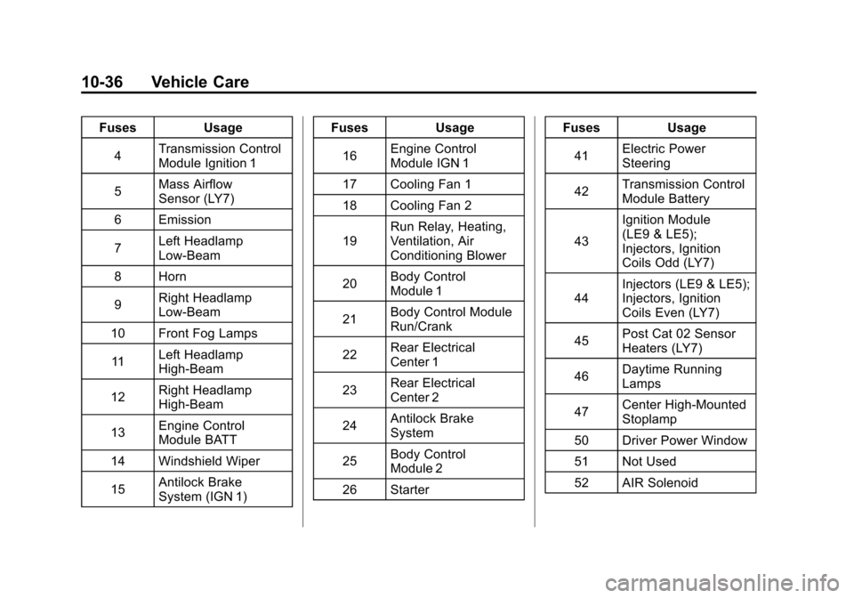
FusesUsage
4 Transmission Control
Module Ignition 1
5 Mass Airflow
Sensor (LY7)
6 Emission
7 Left Headlamp
Low-Beam
8 Horn
9 Right Headlamp
Low-Beam
10 Front Fog Lamps
11 Left Headlamp
High-Beam
12 Right Headlamp
High-Beam
13 Engine Control
Module BATT
14 Windshield Wiper
15 Antilock Brake
System (IGN 1) Fuses
Usage
16 Engine Control
Module IGN 1
17 Cooling Fan 1
18 Cooling Fan 2
19 Run Relay, Heating,
Ventilation, Air
Conditioning Blower
20 Body Control
Module 1
21 Body Control Module
Run/Crank
22 Rear Electrical
Center 1
23 Rear Electrical
Center 2
24 Antilock Brake
System
25 Body Control
Module 2
26 Starter Fuses
Usage
41 Electric Power
Steering
42 Transmission Control
Module Battery
43 Ignition Module
(LE9 & LE5);
Injectors, Ignition
Coils Odd (LY7)
44 Injectors (LE9 & LE5);
Injectors, Ignition
Coils Even (LY7)
45 Post Cat 02 Sensor
Heaters (LY7)
46 Daytime Running
Lamps
47 Center High-Mounted
Stoplamp
50 Driver Power Window
51 Not Used
52 AIR Solenoid
Page 279 of 398
Black plate (39,1)Chevrolet Malibu Owner Manual - 2012
Vehicle Care 10-39
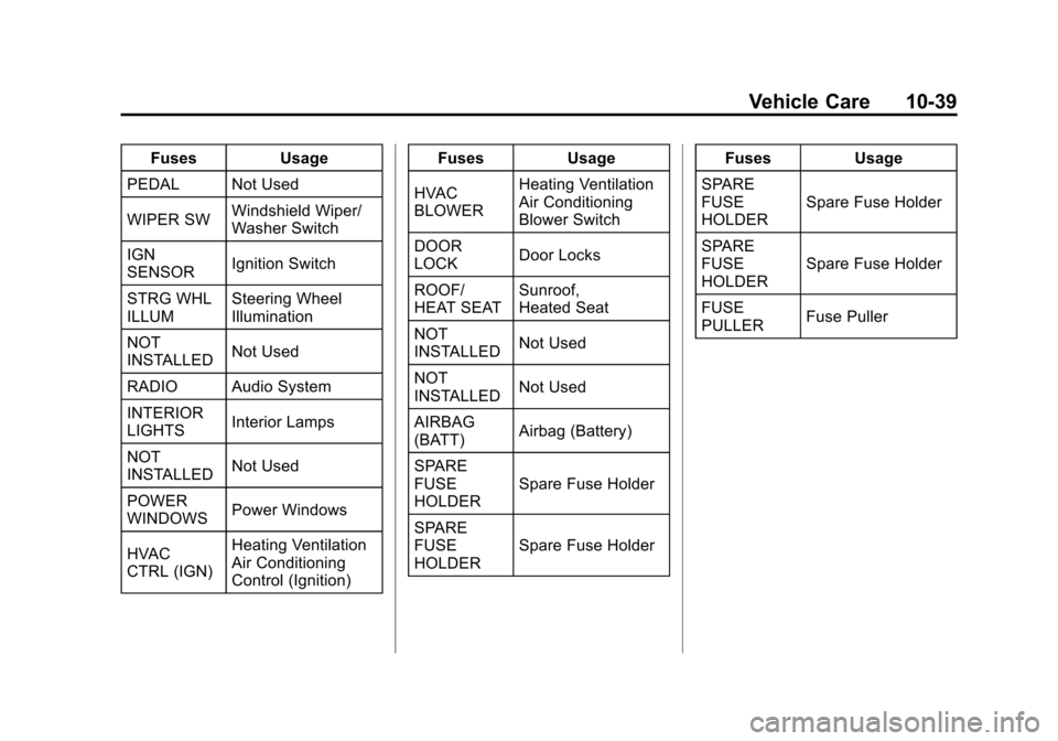
FusesUsage
PEDAL Not Used
WIPER SW Windshield Wiper/
Washer Switch
IGN
SENSOR Ignition Switch
STRG WHL
ILLUM Steering Wheel
Illumination
NOT
INSTALLED Not Used
RADIO Audio System
INTERIOR
LIGHTS Interior Lamps
NOT
INSTALLED Not Used
POWER
WINDOWS Power Windows
HVAC
CTRL (IGN) Heating Ventilation
Air Conditioning
Control (Ignition) Fuses
Usage
HVAC
BLOWER Heating Ventilation
Air Conditioning
Blower Switch
DOOR
LOCK Door Locks
ROOF/
HEAT SEAT Sunroof,
Heated Seat
NOT
INSTALLED Not Used
NOT
INSTALLED Not Used
AIRBAG
(BATT) Airbag (Battery)
SPARE
FUSE
HOLDER Spare Fuse Holder
SPARE
FUSE
HOLDER Spare Fuse Holder Fuses
Usage
SPARE
FUSE
HOLDER Spare Fuse Holder
SPARE
FUSE
HOLDER Spare Fuse Holder
FUSE
PULLER Fuse Puller
Page 281 of 398
Black plate (41,1)Chevrolet Malibu Owner Manual - 2012
Vehicle Care 10-41
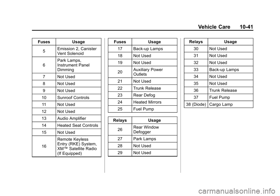
FusesUsage
5 Emission 2, Canister
Vent Solenoid
6 Park Lamps,
Instrument Panel
Dimming
7 Not Used
8 Not Used
9 Not Used
10 Sunroof Controls
11 Not Used
12 Not Used
13 Audio Amplifier
14 Heated Seat Controls
15 Not Used
16 Remote Keyless
Entry (RKE) System,
XM™
Satellite Radio
(If Equipped) Fuses
Usage
17 Back-up Lamps
18 Not Used
19 Not Used
20 Auxiliary Power
Outlets
21 Not Used
22 Trunk Release
23 Rear Defog
24 Heated Mirrors
25 Fuel Pump
Relays Usage
26 Rear Window
Defogger
27 Park Lamps
28 Not Used
29 Not Used Relays
Usage
30 Not Used
31 Not Used
32 Not Used
33 Back-up Lamps
34 Not Used
35 Not Used
36 Trunk Release
37 Fuel Pump
38 (Diode) Cargo Lamp
Page 287 of 398

Black plate (47,1)Chevrolet Malibu Owner Manual - 2012
Vehicle Care 10-47
Accessory Weight:The
combined weight of optional
accessories. Some examples
of optional accessories are
automatic transmission, power
steering, power brakes, power
windows, power seats, and air
conditioning.
Aspect Ratio
:The relationship
of a tire's height to its width.
Belt
:A rubber coated layer of
cords that is located between
the plies and the tread. Cords
may be made from steel or other
reinforcing materials.
Bead
:The tire bead contains
steel wires wrapped by steel
cords that hold the tire onto
the rim.
Bias Ply Tire
:A pneumatic tire
in which the plies are laid at
alternate angles less than
90 degrees to the centerline of
the tread. Cold Tire Pressure
:The
amount of air pressure in a tire,
measured in kPa (kilopascal)
or psi (pounds per square inch)
before a tire has built up heat
from driving. See Tire Pressure
on page 10‑50.
Curb Weight
:The weight of a
motor vehicle with standard and
optional equipment including the
maximum capacity of fuel, oil,
and coolant, but without
passengers and cargo.
DOT Markings
:A code molded
into the sidewall of a tire
signifying that the tire is in
compliance with the U.S.
Department of Transportation
(DOT) Motor Vehicle Safety
Standards. The DOT code
includes the Tire Identification
Number (TIN), an alphanumeric
designator which can also identify the tire manufacturer,
production plant, brand, and
date of production.
GVWR
:Gross Vehicle Weight
Rating. See Vehicle Load Limits
on page 9‑11.
GAWR FRT
:Gross Axle
Weight Rating for the front axle.
See Vehicle Load Limits on
page 9‑11.
GAWR RR
:Gross Axle
Weight Rating for the rear axle.
See Vehicle Load Limits on
page 9‑11.
Intended Outboard Sidewall
:
The side of an asymmetrical tire,
that must always face outward
when mounted on a vehicle.
Kilopascal (kPa)
:The metric
unit for air pressure.
Page 309 of 398
Black plate (69,1)Chevrolet Malibu Owner Manual - 2012
Vehicle Care 10-69
If a tire goes flat, avoid further tire
and wheel damage by driving slowly
to a level place. Turn on the hazard
warning flashers. SeeHazard
Warning Flashers on page 6‑4.
See If a Tire Goes Flat on
page 10‑65 for other important
safety warnings.
Do not remove any objects that
have penetrated the tire.
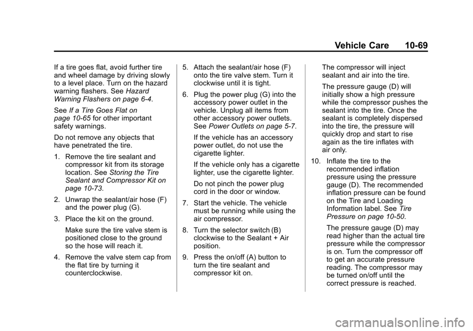
1. Remove the tire sealant and compressor kit from its storage
location. See Storing the Tire
Sealant and Compressor Kit on
page 10‑73.
2. Unwrap the sealant/air hose (F) and the power plug (G).
3. Place the kit on the ground. Make sure the tire valve stem is
positioned close to the ground
so the hose will reach it.
4. Remove the valve stem cap from the flat tire by turning it
counterclockwise. 5. Attach the sealant/air hose (F)
onto the tire valve stem. Turn it
clockwise until it is tight.
6. Plug the power plug (G) into the accessory power outlet in the
vehicle. Unplug all items from
other accessory power outlets.
See Power Outlets on page 5‑7.
If the vehicle has an accessory
power outlet, do not use the
cigarette lighter.
If the vehicle only has a cigarette
lighter, use the cigarette lighter.
Do not pinch the power plug
cord in the door or window.
7. Start the vehicle. The vehicle must be running while using the
air compressor.
8. Turn the selector switch (B) clockwise to the Sealant + Air
position.
9. Press the on/off (A) button to turn the tire sealant and
compressor kit on. The compressor will inject
sealant and air into the tire.
The pressure gauge (D) will
initially show a high pressure
while the compressor pushes the
sealant into the tire. Once the
sealant is completely dispersed
into the tire, the pressure will
quickly drop and start to rise
again as the tire inflates with
air only.
10. Inflate the tire to the recommended inflation
pressure using the pressure
gauge (D). The recommended
inflation pressure can be found
on the Tire and Loading
Information label. See Tire
Pressure on page 10‑50.
The pressure gauge (D) may
read higher than the actual tire
pressure while the compressor
is on. Turn the compressor off
to get an accurate pressure
reading. The compressor may
be turned on/off until the
correct pressure is reached.