2012 BMW 750LI SEDAN clock
[x] Cancel search: clockPage 14 of 299
Instrument cluster
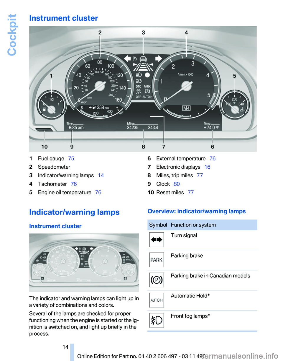
1
Fuel gauge 75
2 Speedometer
3 Indicator/warning lamps 14
4 Tachometer 76
5 Engine oil temperature 766
External temperature 76
7 Electronic displays 16
8 Miles, trip miles 77
9 Clock 80
10 Reset miles 77
Indicator/warning lamps
Instrument cluster The indicator and warning lamps can light up in
a variety of combinations and colors.
Several of the lamps are checked for proper
functioning
when the engine is started or the ig‐
nition is switched on, and light up briefly in the
process. Overview: indicator/warning lamps Symbol Function or system
Turn signal
Parking brake
Parking brake in Canadian models
Automatic Hold*
Front fog lamps* Seite 14
14 Online Edition for Part no. 01 40 2 606 497 - 03 11 490
Cockpit
Page 21 of 299
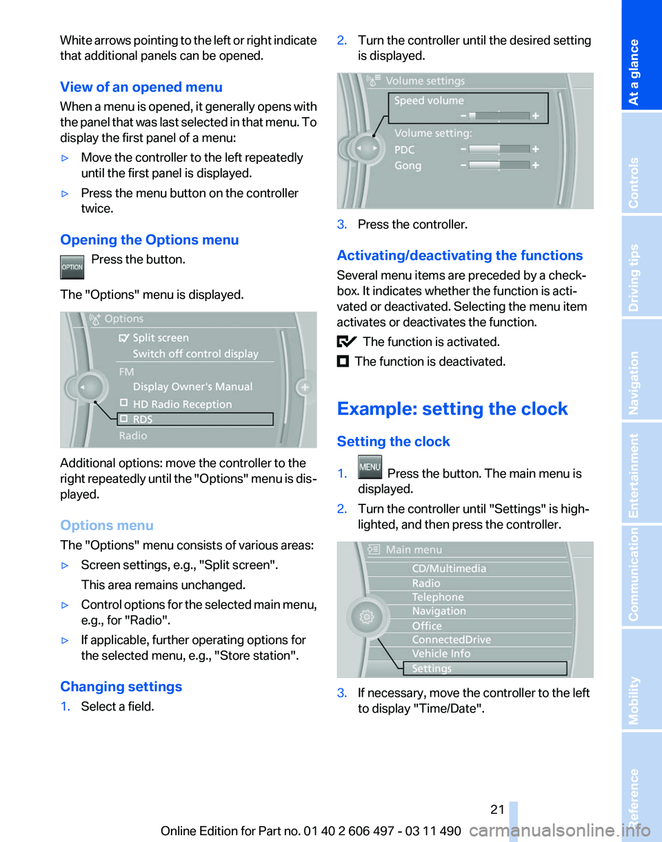
White arrows pointing to the left or right indicate
that additional panels can be opened.
View of an opened menu
When
a menu is opened, it generally opens with
the panel that was last selected in that menu. To
display the first panel of a menu:
▷ Move the controller to the left repeatedly
until the first panel is displayed.
▷ Press the menu button on the controller
twice.
Opening the Options menu Press the button.
The "Options" menu is displayed. Additional options: move the controller to the
right
repeatedly until the "Options" menu is dis‐
played.
Options menu
The "Options" menu consists of various areas:
▷ Screen settings, e.g., "Split screen".
This area remains unchanged.
▷ Control options for the selected main menu,
e.g., for "Radio".
▷ If applicable, further operating options for
the selected menu, e.g.,
"Store station".
Changing settings
1. Select a field. 2.
Turn the controller until the desired setting
is displayed. 3.
Press the controller.
Activating/deactivating the functions
Several menu items are preceded by a check‐
box. It indicates whether the function is acti‐
vated or deactivated. Selecting the menu item
activates or deactivates the function. The function is activated.
The function is deactivated.
Example: setting the clock
Setting the clock
1. Press the button. The main menu is
displayed.
2. Turn the controller until "Settings" is high‐
lighted, and then press the controller. 3.
If necessary, move the controller to the left
to display "Time/Date"
.
Seite 21
21Online Edition for Part no. 01 40 2 606 497 - 03 11 490
Reference Mobility Communication Entertainment Navigation Driving tips Controls
At a glance
Page 75 of 299
Displays
Instrument cluster
At a glance
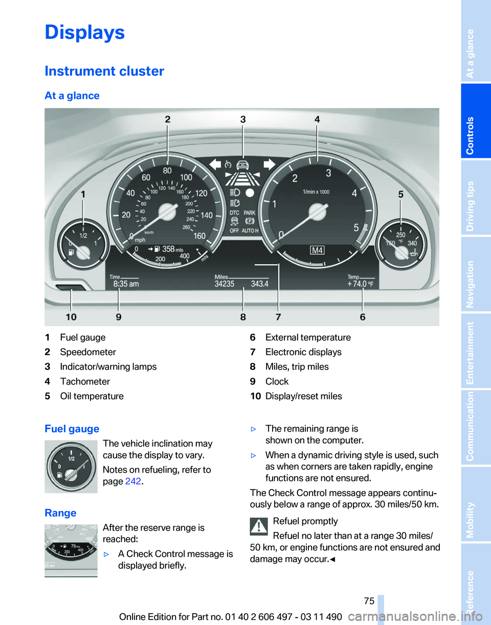
1
Fuel gauge
2 Speedometer
3 Indicator/warning lamps
4 Tachometer
5 Oil temperature 6
External temperature
7 Electronic displays
8 Miles, trip miles
9 Clock
10 Display/reset miles
Fuel gauge The vehicle inclination may
cause the display to vary.
Notes on refueling, refer to
page 242.
Range After the reserve range is
reached:
▷A Check Control message is
displayed briefly. ▷
The remaining range is
shown on the computer.
▷ When a dynamic driving style is used, such
as when corners are taken rapidly, engine
functions are not ensured.
The Check Control message appears continu‐
ously below a range of approx. 30 miles/50 km.
Refuel promptly
Refuel no later than at a range 30 miles/
50
km, or engine functions are not ensured and
damage may occur.◀ Seite 75
75Online Edition for Part no. 01 40 2 606 497 - 03 11 490
Reference Mobility Communication Entertainment Navigation Driving tips
Controls At a glance
Page 88 of 299
Safety
Airbags
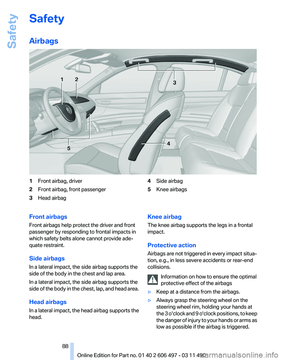
1
Front airbag, driver
2 Front airbag, front passenger
3 Head airbag 4
Side airbag
5 Knee airbags
Front airbags
Front airbags help protect the driver and front
passenger by responding to frontal impacts in
which safety belts alone cannot provide ade‐
quate restraint.
Side airbags
In a lateral impact, the side airbag supports the
side of the body in the chest and lap area.
In a lateral impact, the side airbag supports the
side
of the body in the chest, lap, and head area.
Head airbags
In a lateral impact, the head airbag supports the
head. Knee airbag
The knee airbag supports the legs in a frontal
impact.
Protective action
Airbags are not triggered in every impact situa‐
tion, e.g., in less severe accidents or rear-end
collisions.
Information on how to ensure the optimal
protective effect of the airbags
▷ Keep at a distance from the airbags.
▷ Always grasp the steering wheel on the
steering wheel rim, holding your hands at
the
3 o'clock and 9 o'clock positions, to keep
the danger of injury to your hands or arms as
low as possible if the airbag is triggered. Seite 88
88 Online Edition for Part no. 01 40 2 606 497 - 03 11 490
Safety
Page 242 of 299
Refueling
Fuel cap
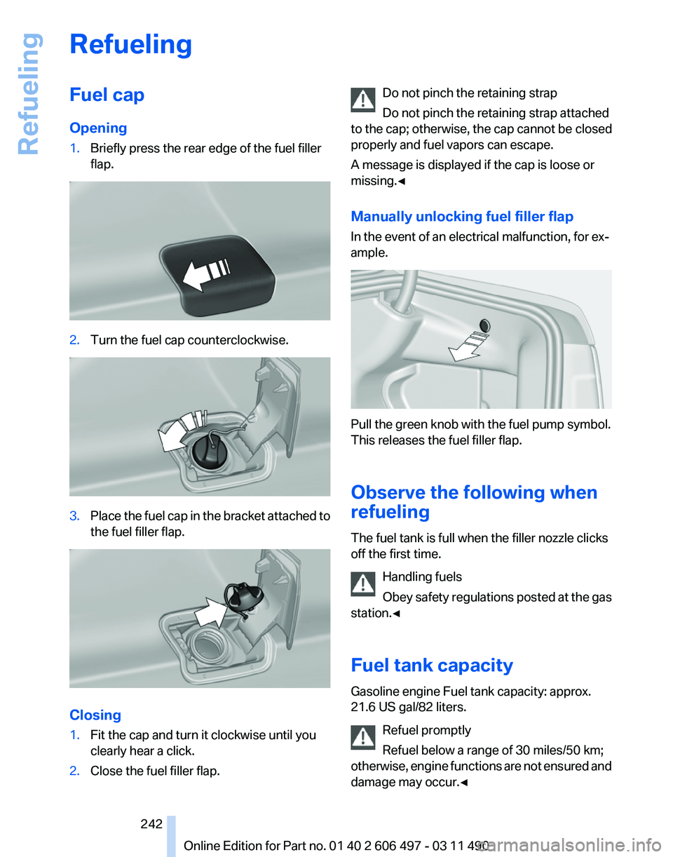
Opening
1.
Briefly press the rear edge of the fuel filler
flap. 2.
Turn the fuel cap counterclockwise. 3.
Place the fuel cap in the bracket attached to
the fuel filler flap. Closing
1.
Fit the cap and turn it clockwise until you
clearly hear a click.
2. Close the fuel filler flap. Do not pinch the retaining strap
Do not pinch the retaining strap attached
to the cap; otherwise, the cap cannot be closed
properly and fuel vapors can escape.
A message is displayed if the cap is loose or
missing.◀
Manually unlocking fuel filler flap
In the event of an electrical malfunction, for ex‐
ample. Pull the green knob with the fuel pump symbol.
This releases the fuel filler flap.
Observe the following when
refueling
The fuel tank is full when the filler nozzle clicks
off the first time.
Handling fuels
Obey
safety regulations posted at the gas
station.◀
Fuel tank capacity
Gasoline engine Fuel tank capacity: approx.
21.6 US gal/82 liters.
Refuel promptly
Refuel below a range of 30 miles/50 km;
otherwise, engine functions are not ensured and
damage may occur.◀ Seite 242
242 Online Edition for Part no. 01 40 2 606 497 - 03 11 490
Refueling
Page 257 of 299
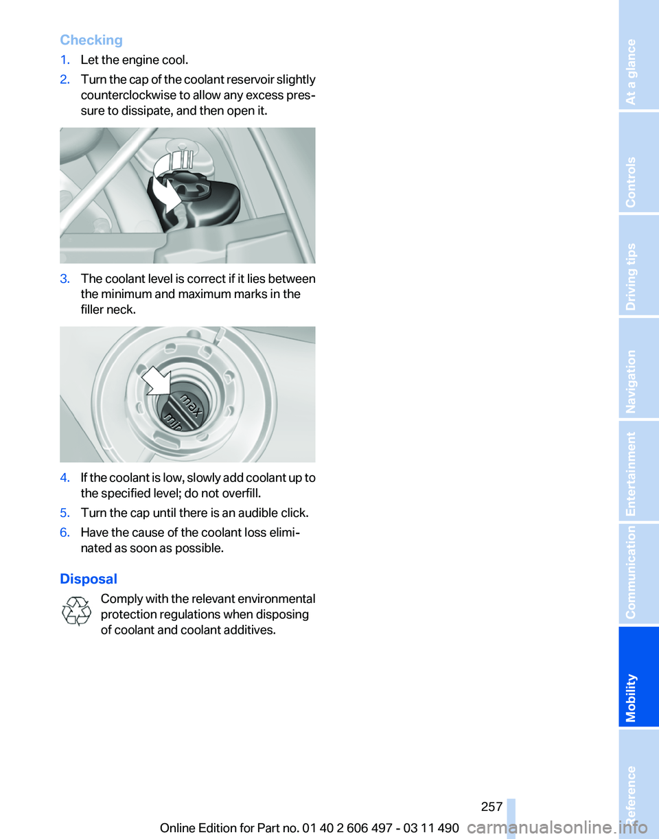
Checking
1.
Let the engine cool.
2. Turn the cap of the coolant reservoir slightly
counterclockwise
to allow any excess pres‐
sure to dissipate, and then open it. 3.
The coolant level is correct if it lies between
the minimum and maximum marks in the
filler neck. 4.
If the coolant is low, slowly add coolant up to
the specified level; do not overfill.
5. Turn the cap until there is an audible click.
6. Have the cause of the coolant loss elimi‐
nated as soon as possible.
Disposal Comply
with the relevant environmental
protection regulations when disposing
of coolant and coolant additives. Seite 257
257Online Edition for Part no. 01 40 2 606 497 - 03 11 490
Reference
Mobility Communication Entertainment Navigation Driving tips Controls At a glance
Page 267 of 299
Assist Response Center may still be able to
hear you.
Initiating an Emergency Request
automatically
Under certain conditions, an Emergency Re‐
quest is automatically initiated immediately after
a severe accident. Automatic Collision Notifica‐
tion is not affected by pressing the SOS button.
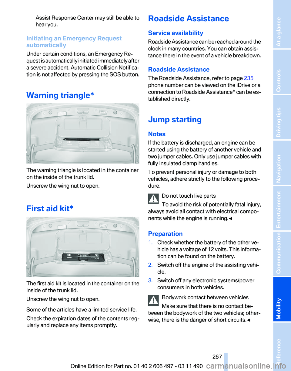
Warning triangle* The warning triangle is located in the container
on the inside of the trunk lid.
Unscrew the wing nut to open.
First aid kit*
The first aid kit is located in the container on the
inside of the trunk lid.
Unscrew the wing nut to open.
Some of the articles have a limited service life.
Check the expiration dates of the contents reg‐
ularly and replace any items promptly. Roadside Assistance
Service availability
Roadside Assistance can be reached around the
clock in many countries. You can obtain assis‐
tance there in the event of a vehicle breakdown.
Roadside Assistance
The Roadside Assistance, refer to page
235
phone number can be viewed on the iDrive or a
connection to Roadside Assistance* can be es‐
tablished directly.
Jump starting
Notes
If the battery is discharged, an engine can be
started using the battery of another vehicle and
two jumper cables. Only use jumper cables with
fully insulated clamp handles.
To prevent personal injury or damage to both
vehicles, adhere strictly to the following proce‐
dure.
Do not touch live parts
To avoid the risk of potentially fatal injury,
always avoid all contact with electrical compo‐
nents while the engine is running.◀
Preparation
1. Check whether the battery of the other ve‐
hicle has a voltage of 12 volts. This informa‐
tion can be found on the battery.
2. Switch off the engine of the assisting vehi‐
cle.
3. Switch off any electronic systems/power
consumers in both vehicles.
Bodywork contact between vehicles
Make sure that there is no contact be‐
tween the bodywork of the two vehicles; other‐
wise, there is the danger of short circuits.◀ Seite 267
267Online Edition for Part no. 01 40 2 606 497 - 03 11 490
Reference
Mobility Communication Entertainment Navigation Driving tips Controls At a glance
Page 289 of 299
Battery replacement, audio re‐
mote control 198
Battery replacement, remote control, rear entertain‐
ment 200
Battery replacement, vehicle battery 265
Battery replacement, vehicle remote control 32
Battery, vehicle 265
Before entering the car wash 271
Belts, safety belts 53
Beverage holder, cu‐ pholder 140
Blinds, sun protection 45
Bluetooth audio 194
BMW Apps 238
BMW Apps, video play‐ back 193
BMW Assist 234
BMW EfficientDynamics, refer to Saving fuel 148
BMW homepage 6
BMW Internet page 6
BMW Maintenance Sys‐ tem 258
BMW Online 236
Bottle holder, refer to Cu‐ pholder 140
Brake assistant 98
Brake assistant, adaptive 98
Brake discs, breaking in 144
Brake force display 97
Brake lamps, brake force dis‐ play 97
Brake lamps, bulb replace‐ ment 263
Brake lights, adaptive 97
Brake pads, breaking in 144
Braking, notes 145
Breakdown assis‐ tance 266, 267
Breaking in 144
Brightness of Control Dis‐ play 81
Bulb replacement 260
Bulb replacement, front 261 Bulb replacement, rear
263
Bulbs and lamps 260
Button, RES 107
Button, Start/Stop 65
Bypassing, refer to starting aid 267
C
Calendar 228
California Proposition 65 Warning 7
Camera, backup camera 118
Camera, care 273
Camera, Side View 119
Camera, Top View 120
Can holder, refer to Cu‐ pholder 140
Car battery 265
Car care products 272
Care, displays 273
Care, vehicle 272
Cargo 146
Cargo area lid 39
Cargo area, storage compart‐ ments 140
Cargo straps, securing cargo 147
Car key, refer to Remote con‐ trol 32
Carpet, care 273
Car wash 271
Catalytic converter, refer to Hot exhaust system 144
CBS Condition Based Serv‐ ice 258
CD/DVD 179
CD/DVD player, rear 199, 204
CDs, storing 186
Cell phone 212
Center armrest 139
Center console 17
Central locking system 35
Central
screen, refer to Control
Display 19
Changes, technical, refer to Safety 7
Changing parts 260 Changing wheels/tires 250
Check Control 82
Children, seating position 61
Children, transporting safely 61
Child restraint fixing sys‐ tem 61
Child restraint fixing system LATCH 62
Child restraint fixing systems, mounting 61
Child-safety locks 64
Child seat, mounting 61
Child seats 61
Chrome parts, care 272
Cigarette lighter 134
Cleaning, displays 273
Climate control 125
Climate control on head‐ liner 130
Climate control wind‐ shield 145
Clock 77
Closing/opening from in‐ side 39
Closing/opening via door lock 38
Closing/opening with remote control 36
Clothes hooks 140
Collision warning 110
Combination instrument 14
Combination
instrument, elec‐
tronic displays 16
Combination switch, refer to Turn signals 70
Combination switch, refer to Wiper system 70
Comfort Access 42
COMFORT program, Dynamic Driving Control 103
Computer 77
Concierge service 235
Condensation on win‐ dows 126
Condensation under the vehi‐ cle 146
Seite 289
289Online Edition for Part no. 01 40 2 606 497 - 03 11 490
Reference Mobility Communication Entertainment Navigation Driving tips Controls At a glance