2012 BMW 750I XDRIIVE SEDAN check engine light
[x] Cancel search: check engine lightPage 132 of 299
Interior equipment
Integrated universal remote
control*
The concept
This system can replace up to three different
hand-held transmitters for various types of re‐
mote-controlled equipment, such as garage
doors or lighting systems.
The hand-held transmitter signal can be pro‐
grammed on one of the three memory buttons.
The
corresponding device can then be operated
using the programmed memory button.
The LED indicates that a signal is being trans‐
mitted.
When selling the vehicle, delete the stored pro‐
grams for security reasons.
During programming
During programming and before activat‐
ing a device using the universal remote control,
ensure that there are no people, animals, or ob‐
jects in the range of movement of the remote-
controlled device; otherwise, there is a risk of
injury or damage.
Also follow the safety instructions of the hand-
held transmitter.◀
Compatibility
If this symbol is printed on the packaging
or in the instructions of the hand-held
transmitter, the remote-controlled de‐
vice is generally compatible with the universal
remote control.
If you have any questions, please contact:
▷ Your service center.
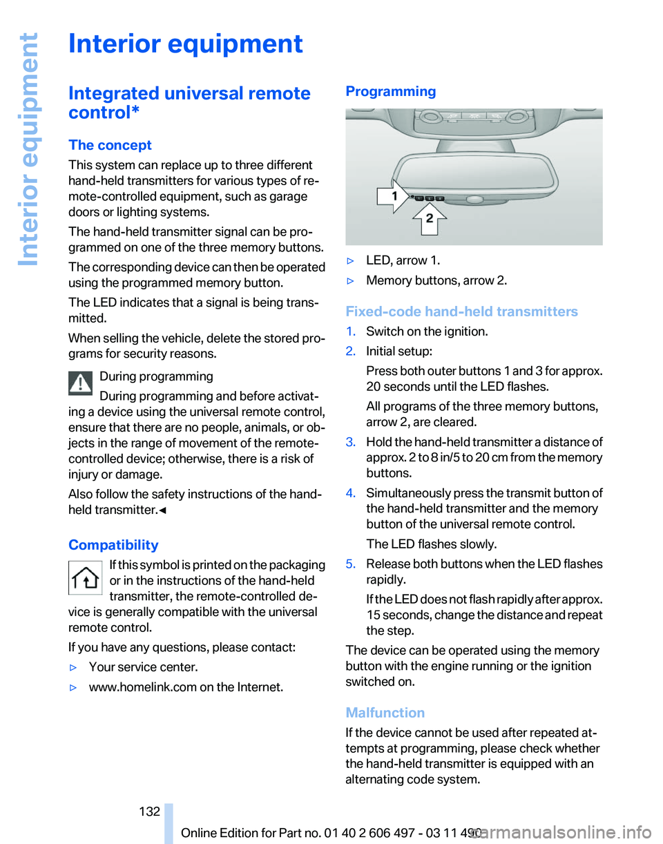
▷ www.homelink.com on the Internet. Programming
▷
LED, arrow 1.
▷ Memory buttons, arrow 2.
Fixed-code hand-held transmitters
1. Switch on the ignition.
2. Initial setup:
Press
both outer buttons 1 and 3 for approx.
20 seconds until the LED flashes.
All programs of the three memory buttons,
arrow 2, are cleared.
3. Hold the hand-held transmitter a distance of
approx.
2 to 8 in/5 to 20 cm from the memory
buttons.
4. Simultaneously press the transmit button of
the hand-held transmitter and the memory
button of the universal remote control.
The LED flashes slowly.
5. Release both buttons when the LED flashes
rapidly.
If
the LED does not flash rapidly after approx.
15 seconds, change the distance and repeat
the step.
The device can be operated using the memory
button with the engine running or the ignition
switched on.
Malfunction
If the device cannot be used after repeated at‐
tempts at programming, please check whether
the hand-held transmitter is equipped with an
alternating code system.
Seite 132
132 Online Edition for Part no. 01 40 2 606 497 - 03 11 490
Interior equipment
Page 149 of 299
Attached parts on the vehicle impair the aero‐
dynamics and increase the fuel consumption.
Close the windows and glass sunroof
*
Driving with the glass sunroof and windows
open results in increased air resistance and
raises fuel consumption.
Check the tire inflation pressure
regularly
Check and, if necessary, correct the tire inflation
pressure at least twice a month and before start‐
ing on a long trip.
Low tire inflation pressure increases rolling re‐
sistance and thus raises fuel consumption and
tire wear.
Drive away without delay
Do not wait for the engine to warm up while the
vehicle remains stationary. Start driving right
away, but at moderate engine speeds.
This is the fastest way for the cold engine to
reach its operating temperature.
Look well ahead when driving
Avoid unnecessary acceleration and braking.
By maintaining a suitable distance to the vehicle
driving ahead of you.
Driving smoothly and looking ahead reduces
fuel consumption.
Use coasting conditions
When approaching a red light, take your foot off
the accelerator and let the vehicle coast to a halt.
On a downhill gradient, take your foot off the ac‐
celerator and let the vehicle roll.
The flow of fuel is interrupted while coasting.
Switch off the engine during longer
stops
Switch off the engine during longer stops, e.g.,
at traffic lights, railroad crossings or in traffic
congestion.
Fuel savings are achieved after the vehicle is
switched off for only approx. 4 seconds. Switch off any functions that are not
currently needed
Functions
such as seat heating and the rear win‐
dow defroster require a lot of energy and con‐
sume additional fuel, especially in city and stop-
and-go traffic.
Therefore, switch off these functions if they are
not actually needed.
Have maintenance carried out
Have vehicles maintained regularly to achieve
optimal vehicle economy and operating life.
Have the maintenance carried out by your serv‐
ice center.
Please also note the BMW Maintenance Sys‐
tem.
Seite 149
149Online Edition for Part no. 01 40 2 606 497 - 03 11 490
Reference Mobility Communication Entertainment Navigation
Driving tips Controls At a glance
Page 256 of 299
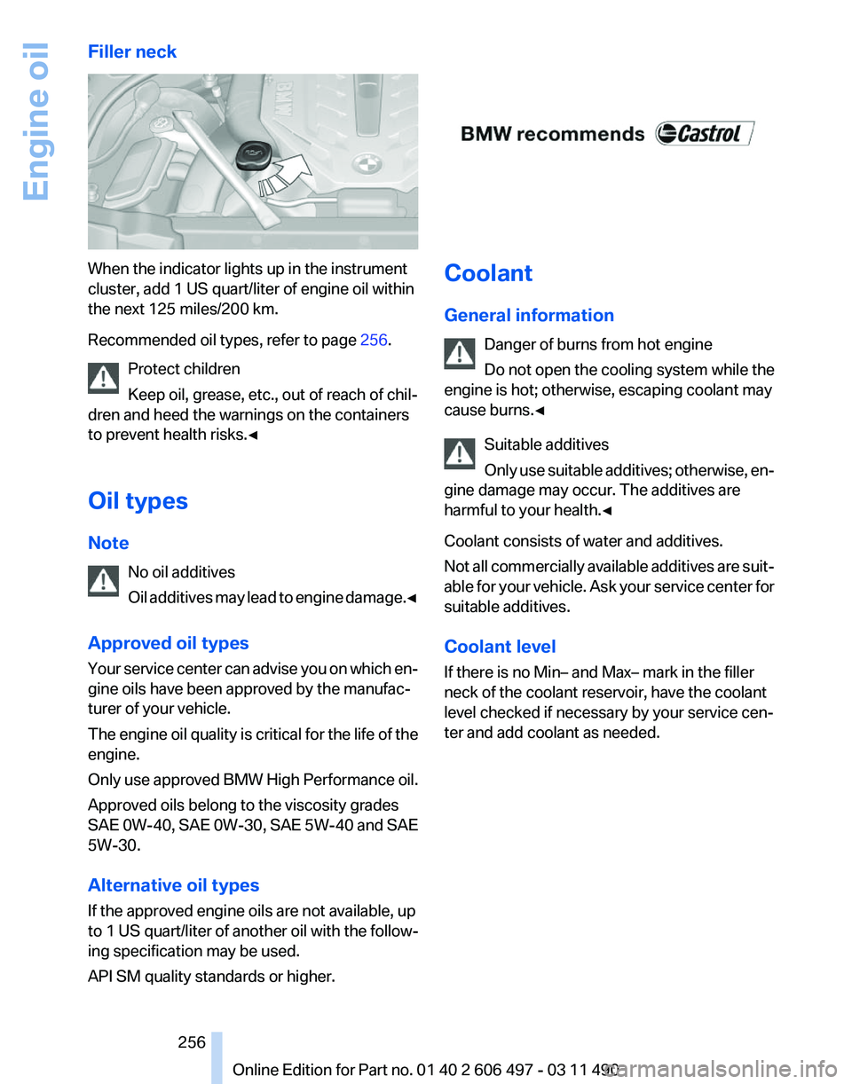
Filler neck
When the indicator lights up in the instrument
cluster, add 1 US quart/liter of engine oil within
the next 125 miles/200 km.
Recommended oil types, refer to page
256.
Protect children
Keep oil, grease, etc., out of reach of chil‐
dren and heed the warnings on the containers
to prevent health risks.◀
Oil types
Note
No oil additives
Oil
additives may lead to engine damage.◀
Approved oil types
Your service center can advise you on which en‐
gine oils have been approved by the manufac‐
turer of your vehicle.
The engine oil quality is critical for the life of the
engine.
Only use approved BMW High Performance oil.
Approved oils belong to the viscosity grades
SAE 0W-40, SAE 0W-30, SAE 5W-40 and SAE
5W-30.
Alternative oil types
If the approved engine oils are not available, up
to 1 US quart/liter of another oil with the follow‐
ing specification may be used.
API SM quality standards or higher. Coolant
General information
Danger of burns from hot engine
Do not open the cooling system while the
engine is hot; otherwise, escaping coolant may
cause burns.◀
Suitable additives
Only
use suitable additives; otherwise, en‐
gine damage may occur. The additives are
harmful to your health.◀
Coolant consists of water and additives.
Not all commercially available additives are suit‐
able for your vehicle. Ask your service center for
suitable additives.
Coolant level
If there is no Min– and Max– mark in the filler
neck of the coolant reservoir, have the coolant
level checked if necessary by your service cen‐
ter and add coolant as needed. Seite 256
256 Online Edition for Part no. 01 40 2 606 497 - 03 11 490
Engine oil
Page 257 of 299
Checking
1.
Let the engine cool.
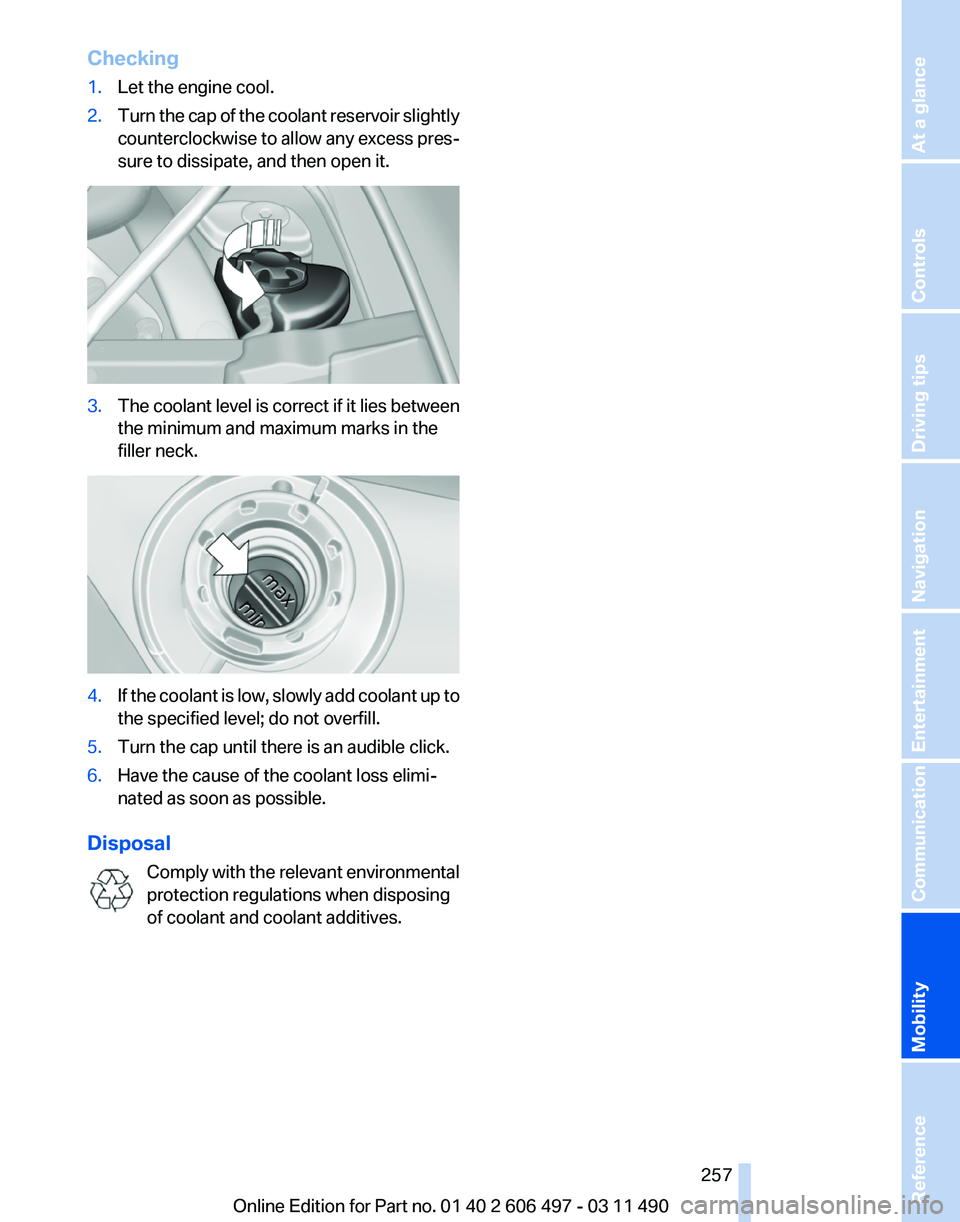
2. Turn the cap of the coolant reservoir slightly
counterclockwise
to allow any excess pres‐
sure to dissipate, and then open it. 3.
The coolant level is correct if it lies between
the minimum and maximum marks in the
filler neck. 4.
If the coolant is low, slowly add coolant up to
the specified level; do not overfill.
5. Turn the cap until there is an audible click.
6. Have the cause of the coolant loss elimi‐
nated as soon as possible.
Disposal Comply
with the relevant environmental
protection regulations when disposing
of coolant and coolant additives. Seite 257
257Online Edition for Part no. 01 40 2 606 497 - 03 11 490
Reference
Mobility Communication Entertainment Navigation Driving tips Controls At a glance
Page 258 of 299
Maintenance
BMW Maintenance System
The maintenance system directs you to re‐
quired
maintenance measures and thereby sup‐
ports you in maintaining road safety and the op‐
erational reliability of the vehicle.
Condition Based Service CBS
Sensors and special algorithms take into ac‐
count the driving conditions of your vehicle.
Based on this, Condition Based Service deter‐
mines the maintenance requirements.
The system makes it possible to adapt the
amount of maintenance you need to your user
profile.
Details on the service requirements, refer to
page 81, can be displayed on the Control Dis‐
play.
Service data in the remote control
Information on the required maintenance is con‐
tinuously stored in the remote control. Your
service center will read out this data and suggest
the right array of service procedures for your ve‐
hicle.
Therefore, hand your service specialist the re‐
mote control that you used most recently.
Storage periods
Storage periods during which the vehicle bat‐
tery was disconnected are not taken into ac‐
count.
If this occurs, have a service center update the
time-dependent maintenance procedures,
such as checking brake fluid and, if necessary,
changing the engine oil and the microfilter/acti‐
vated-charcoal filter. Service and Warranty
Information Booklet for US
models and Warranty and
Service Guide Booklet for
Canadian models
Please
consult your Service and Warranty Infor‐
mation Booklet for US models and Warranty and
Service Guide Booklet for Canadian models for
additional information on service requirements.
Maintenance and repair should be performed by
your service center. Make sure to have regular
maintenance procedures recorded in the vehi‐
cle's Service and Warranty Information Booklet
for US models, and in the Warranty and Service
Guide Booklet for Canadian models. These en‐
tries are proof of regular maintenance.
Socket for OBD Onboard
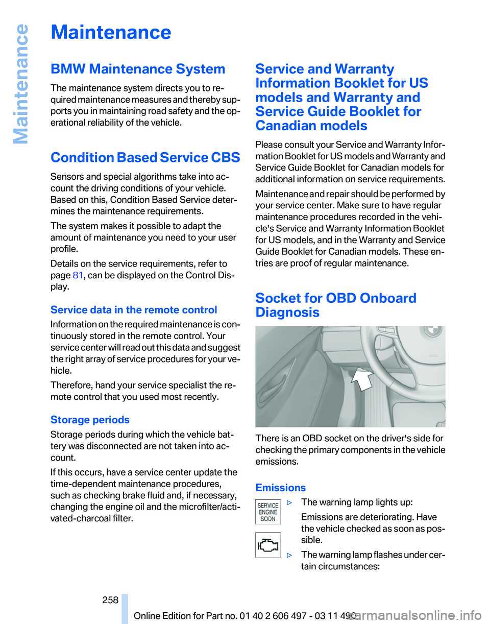
Diagnosis There is an OBD socket on the driver's side for
checking
the primary components in the vehicle
emissions.
Emissions
▷The warning lamp lights up:
Emissions are deteriorating. Have
the
vehicle checked as soon as pos‐
sible.
▷ The warning lamp flashes under cer‐
tain circumstances: Seite 258
258 Online Edition for Part no. 01 40 2 606 497 - 03 11 490
Maintenance
Page 259 of 299
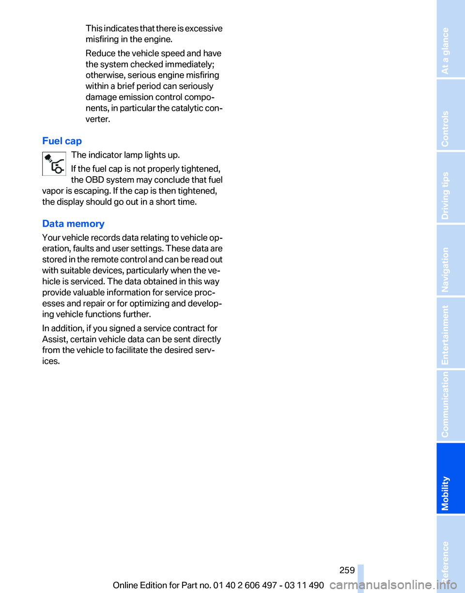
This indicates that there is excessive
misfiring in the engine.
Reduce the vehicle speed and have
the system checked immediately;
otherwise, serious engine misfiring
within a brief period can seriously
damage emission control compo‐
nents,
in particular the catalytic con‐
verter.
Fuel cap The indicator lamp lights up.
If the fuel cap is not properly tightened,
the
OBD system may conclude that fuel
vapor is escaping. If the cap is then tightened,
the display should go out in a short time.
Data memory
Your vehicle records data relating to vehicle op‐
eration, faults and user settings. These data are
stored in the remote control and can be read out
with suitable devices, particularly when the ve‐
hicle is serviced. The data obtained in this way
provide valuable information for service proc‐
esses and repair or for optimizing and develop‐
ing vehicle functions further.
In addition, if you signed a service contract for
Assist, certain vehicle data can be sent directly
from the vehicle to facilitate the desired serv‐
ices. Seite 259
259Online Edition for Part no. 01 40 2 606 497 - 03 11 490
Reference
Mobility Communication Entertainment Navigation Driving tips Controls At a glance
Page 261 of 299
Do not touch the bulbs
Do not touch the glass of new bulbs with
your bare hands, as even minute amounts of
contamination will burn into the bulb's surface
and reduce its service life.
Use
a clean tissue, cloth or something similar, or
hold the bulb by its base.◀
Light-emitting diodes (LEDs)
Light-emitting diodes installed behind a cover
serve as the light source for controls, display el‐
ements and other equipment.
These light-emitting diodes, which are related
to conventional lasers, are officially designated
as Class 1 light-emitting diodes.
Do not remove the covers
Do not remove the covers, and never stare
into the unfiltered light for several hours; other‐
wise, irritation of the retina could result.◀
Headlamp glass
Condensation can form on the inside of the ex‐
ternal lamps in cool or humid weather. When the
light is switched on, the condensation evapo‐
rates after a short time. The headlamp glasses
do not need to be changed.
If there is a large amount of moisture, e.g., water
droplets form in the lamp, have it checked by
your service center.
Front lamps, bulb replacement
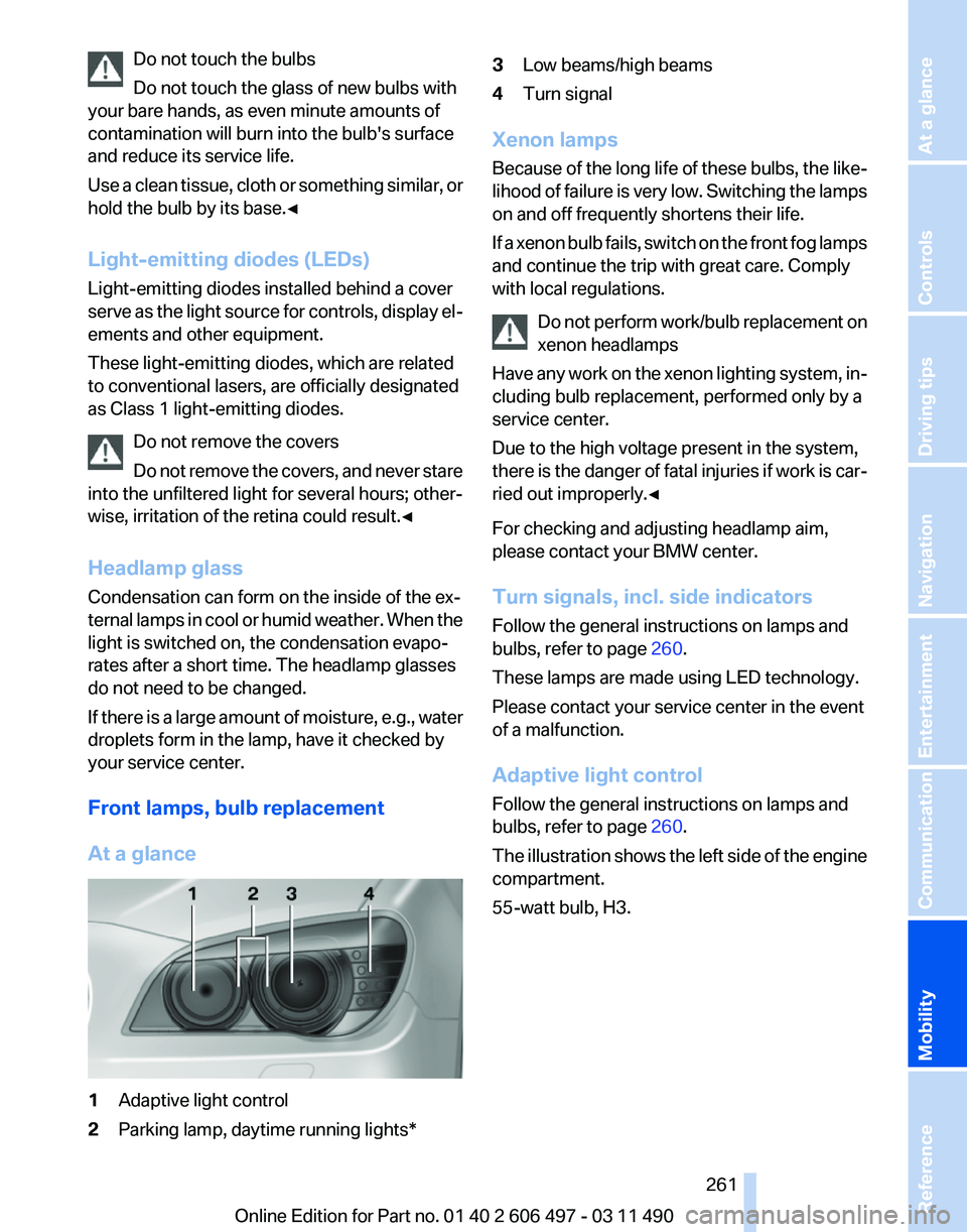
At a glance 1
Adaptive light control
2 Parking lamp, daytime running lights* 3
Low beams/high beams
4 Turn signal
Xenon lamps
Because
of the long life of these bulbs, the like‐
lihood of failure is very low. Switching the lamps
on and off frequently shortens their life.
If a xenon bulb fails, switch on the front fog lamps
and continue the trip with great care. Comply
with local regulations.
Do not perform work/bulb replacement on
xenon headlamps
Have any work on the xenon lighting system, in‐
cluding bulb replacement, performed only by a
service center.
Due to the high voltage present in the system,
there is the danger of fatal injuries if work is car‐
ried out improperly.◀
For checking and adjusting headlamp aim,
please contact your BMW center.
Turn signals, incl. side indicators
Follow the general instructions on lamps and
bulbs, refer to page 260.
These lamps are made using LED technology.
Please contact your service center in the event
of a malfunction.
Adaptive light control
Follow the general instructions on lamps and
bulbs, refer to page 260.
The illustration shows the left side of the engine
compartment.
55-watt bulb, H3. Seite 261
261Online Edition for Part no. 01 40 2 606 497 - 03 11 490
Reference
Mobility Communication Entertainment Navigation Driving tips Controls At a glance
Page 290 of 299

Condition Based Service
CBS 258
Confirmation signal 37
Contacts 223, 232
Control Display 19
Control Display, settings 80
Controller 19
Control systems, driving sta‐ bility 98
Convenient opening 36
Coolant 256
Coolant temperature 76
Cooler 135
Cooling function 127
Cooling, maximum 126
Cooling system 256
Corrosion on brake discs 146
Cruise control 111
Cruise control, active with Stop & Go 105
Cruising range 75
Cupholder 140
Curb weight 278
Current fuel consumption 76
Current location, storing 154
Customer Relations 237
D
Damage, tires 249
Damping control, dy‐ namic 100
Data, technical 276
Date 77
Daytime running lights 85
Defrosting, refer to Windows, defrosting 126
Destination distance 78
Destination guidance 159
Destination guidance with in‐ termediate destinations 158
Destination input, naviga‐ tion 152
Digital clock 77
Digital radio 173
Dimensions 276
Dimmable interior rearview mirror 59 Direction indicator, refer to
Turn signals 70
Display in front wind‐ shield 123
Display,
instrument cluster 75
Display lighting, refer to Instru‐ ment lighting 87
Displays 14
Displays, cleaning 273
Disposal, coolant 257
Disposal, vehicle battery 265
Distance control, refer to PDC 113
Distance, selecting for ACC 106
Distance to destination 78
Divided screen view, split screen 23
Door lock, refer to Remote control 32
Doors, Automatic Soft Clos‐ ing 39
Downhill control 99
Drive-off assistant 98
Drive-off assistant, refer to DSC 98
Driving instructions, breaking in 144
Driving notes, general 144
Driving stability control sys‐ tems 98
Driving tips 144
DSC Dynamic Stability Con‐ trol 98
DTC Dynamic Traction Con‐ trol 99
DVD/CD 179
DVD/CD notes 185
DVD/CD player, rear 199, 204
DVD changer 183
DVD settings 182
DVDs, storing 186
DVD, video 181
Dynamic Damping Con‐ trol 100
Dynamic destination guid‐ ance 165
Dynamic Drive 100 Dynamic Driving Control
102
Dynamic Stability Control DSC 98
Dynamic Traction Control DTC 99
E
EfficientDynamics, refer to Saving fuel 148
Electronic displays, instru‐ ment cluster 16
Electronic engine oil level check 255
Electronic Stability Program ESP, refer to DSC 98
Emergency detection, remote control 33
Emergency release, door lock 38
Emergency release, fuel filler flap 242
Emergency release, parking brake 67
Emergency Request 266
Emergency service, refer to Roadside Assistance 267
Emergency start function, en‐ gine start 33
Emergency unlocking, trunk lid 42
Energy Control 76
Energy recovery 77
Engine compartment 253
Engine compartment, working in 253
Engine coolant 256
Engine oil 255
Engine oil, adding 255
Engine oil additives 256
Engine oil filler neck 255
Engine oil temperature 76
Engine oil types, alterna‐ tive 256
Engine oil types, ap‐ proved 256
Engine start during malfunc‐ tion 33
Seite 290
290 Online Edition for Part no. 01 40 2 606 497 - 03 11 490
Everything from A to Z