2012 BMW 650I XDRIVE COUPE lights
[x] Cancel search: lightsPage 137 of 303
was interrupted by the hand-held transmit‐
ter, hold down the memory button and press
and release the button on the hand-held
transmitter again for 2 seconds.6.To program other hand-held transmitters,
repeat steps 3 to 5.
The device can be operated using the memory
button with the engine running or the ignition
switched on.
Malfunction
If the device cannot be used after repeated at‐
tempts at programming, please check whether
the hand-held transmitter is equipped with an
alternating code system.
To do so:
▷Read the instructions of the hand-held
transmitter.▷Hold down the memory button of the
integrated universal remote control longer.
If the LED of the integrated universal remote
control flashes rapidly for a brief period and then
lights up continuously, the hand-held transmit‐
ter is equipped with an alternating code system.
In this case, program the memory buttons as
described under Alternating-code hand-held
transmitters.
Alternating-code hand-held
transmitters
Please obtain information on synchronizing the
device in the operating manual of the device be‐
ing set up.
Programming will be easier with the aid of a sec‐
ond person.
1.Park the vehicle within range of the remote-
controlled device.2.Program the integrated universal remote
control as described above under Fixed-
code hand-held transmitters.3.Locate the button on the receiver of the de‐
vice to be set, e.g., on the drive.4.Press the button on the receiver of the de‐
vice to be set. You have approx. 30 seconds
for the next step.5.Hold down the programmed memory button
of the integrated universal remote for ap‐
prox. 3 seconds. Repeat this work step, if
necessary, up to three times.
The device can be operated using the memory
button with the engine running or the ignition
switched on.
Reassigning individual programs
1.Switch on the ignition.2.Hold the hand-held transmitter a distance of
approx. 1 to 3 in/2.5 to 8 cm from the mem‐
ory buttons.
The required distance depends on the
manual transmitter.3.Hold down the memory button of the
integrated universal remote control.4.If the LED flashes slowly after approx.
20 seconds, press the transmit button on
the hand-held transmitter.5.Release both buttons when the LED flashes
rapidly.
If the LED does not flash rapidly after approx.
60 seconds, change the distance and repeat
the step.
Canada: if the LED is not flashing rapidly after
approx. 60 seconds, change the distance and
repeat the step, or, if the programming was in‐
terrupted by the hand-held transmitter, hold
down the memory button and press and release
the button on the hand-held transmitter again
for 2 seconds.
Deleting all stored programs
Press the two outer memory buttons for approx.
20 seconds until the LED flashes rapidly.
All stored programs are deleted.
The programs cannot be deleted individually.
Seite 137Interior equipmentControls137
Online Edition for Part no. 01 40 2 607 971 - 09 11 490
Page 152 of 303
The gear shift indicator of your vehicle indicates
the most fuel efficient gear.
Use coasting conditions
When approaching a red light, take your foot off
the accelerator and let the vehicle coast to a halt.
On a downhill gradient, take your foot off the ac‐
celerator and let the vehicle roll.
The flow of fuel is interrupted while coasting.
Switch off the engine during
longer stops
Switch off the engine during longer stops, e.g.,
at traffic lights, railroad crossings or in traffic
congestion.
Fuel savings are achieved after the vehicle is
switched off for only approx. 4 seconds.
The Automatic Engine Start/Stop Function of
your vehicle automatically switches off the en‐
gine during a stop.
Switch off any functions that
are not currently needed
Functions such as seat heating and the rear win‐
dow defroster require a lot of energy and con‐
sume additional fuel, especially in city and stop-
and-go traffic.
Therefore, switch off these functions if they are
not actually needed.
Have maintenance carried out
Have vehicles maintained regularly to achieve
optimal vehicle economy and operating life.
Have the maintenance carried out by your serv‐
ice center.
Please also note the BMW Maintenance Sys‐
tem, refer to page 260.ECO PRO
The concept
ECO PRO supports a driving style that saves on
fuel consumption. For this purpose, the engine
control and comfort functions, e. g. the climate
control output, are adjusted.
In addition, context-sensitive instructions can
be displayed that assist in driving in a manner
that optimizes fuel consumption.
The extension of the range that is achieved as a
result can be displayed in the instrument cluster.
Activating ECO PRO Button should be pressed and held until
ECO PRO is displayed in the instru‐
ment cluster.
Display in the instrument cluster
ECO PRO bonus range An extension of the range can be
achieved by an adjusted driving
style.
This is displayed as the bonus
range in the instrument cluster.
Driving style In the tachometer, a mark in the
bar indicator indicates the cur‐
rent efficiency of the driving style
corresponding to the accelerator
pedal position.▷Blue display: efficient driving style as long as
the mark moves within the blue range.▷Gray display: adjust driving style, e. g. by
backing off the accelerator pedal.
The display switches to blue as soon as all con‐
ditions for fuel-economy-optimized driving are
met.
Seite 152Driving tipsSaving fuel152
Online Edition for Part no. 01 40 2 607 971 - 09 11 490
Page 257 of 303
Engine oilVehicle equipment
All standard, country-specific and optional
equipment that is offered in the model series is
described in this chapter. Therefore, equipment
is also described that is not available in a vehicle,
e. g., because of the selected optional equip‐
ment or country variant. This also applies for
safety-related functions and systems.
General information
The engine oil consumption is dependent on the
driving style and driving conditions.
Therefore, regularly check the engine oil level
after refueling.
Check oil level
The concept
The oil level is monitored electronically and dis‐
played on the Control Display.
Requirements▷The engine must be running and warm after
the vehicle has been driven for at least
6 miles/10 km.▷The vehicle is stopped or being driven on a
level roadway.
Displaying the oil level
1."Vehicle Info"2."Vehicle status"3. "Engine oil level"
Possible messages
▷"Engine oil level OK"▷"Measurement not possible at this time."▷"Measuring engine oil level..."Duration with the engine running: ap‐
prox. 3 minutes.
Duration while driving: approx. 5 minutes.▷"Engine oil level below minimum. Add 1
quart!"
Add oil within the next 125 miles/200 km.▷"Engine oil level too high! Have this
checked."
Have the vehicle checked immediately.
Too much engine oil
Have the vehicle checked immedi‐
ately; otherwise, surplus oil can lead to en‐
gine damage.◀▷"Measurement inactive. Have this
checked."
Note the newly calculated remaining mile‐
age until the next oil service. Have the sys‐
tem checked as soon as possible.
Adding engine oil
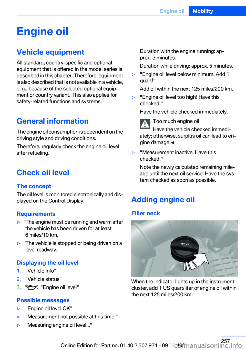
Filler neck
When the indicator lights up in the instrument
cluster, add 1 US quart/liter of engine oil within
the next 125 miles/200 km.
Seite 257Engine oilMobility257
Online Edition for Part no. 01 40 2 607 971 - 09 11 490
Page 261 of 303
Socket for OBD Onboard
Diagnosis
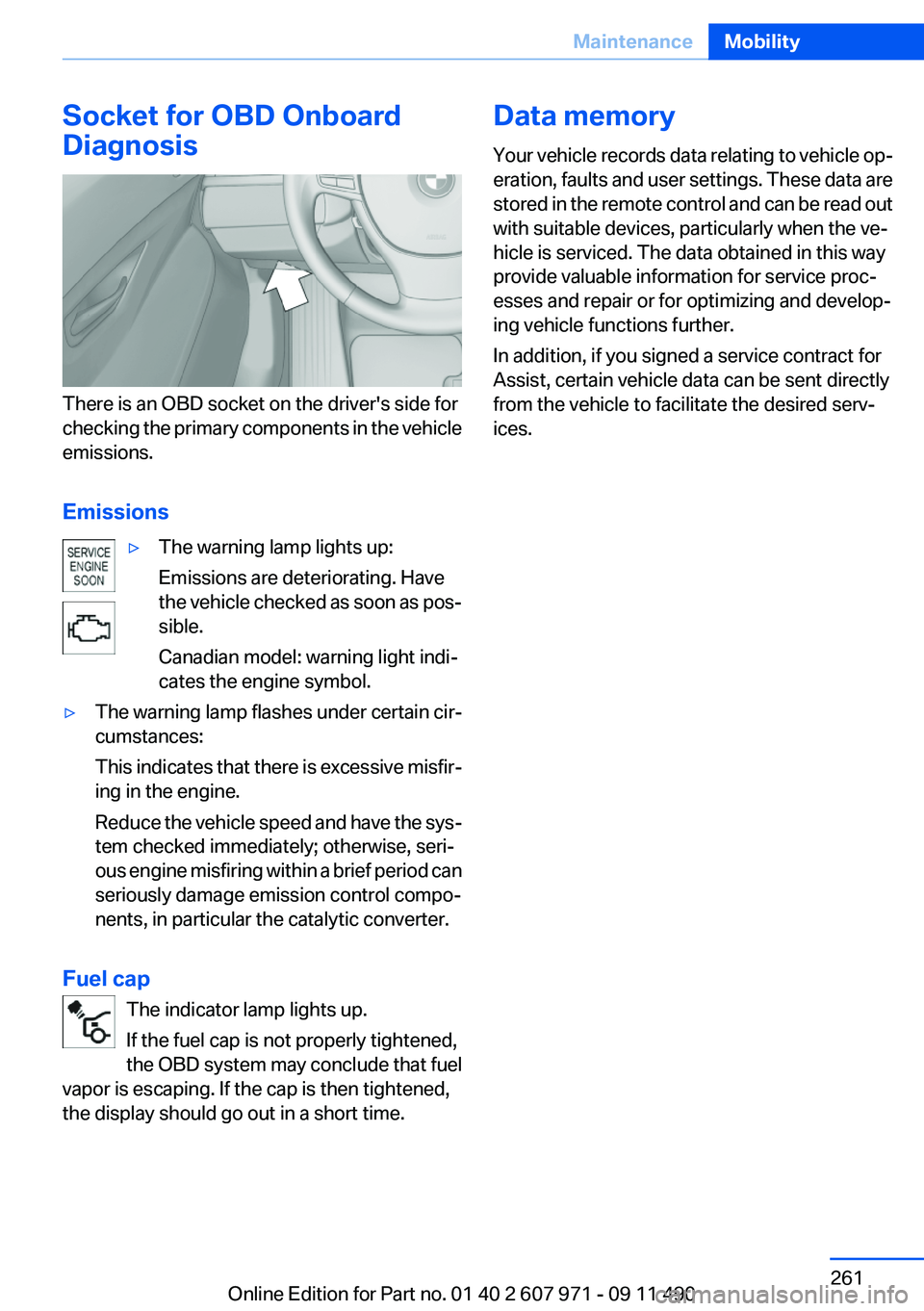
There is an OBD socket on the driver's side for
checking the primary components in the vehicle
emissions.
Emissions
▷The warning lamp lights up:
Emissions are deteriorating. Have
the vehicle checked as soon as pos‐
sible.
Canadian model: warning light indi‐
cates the engine symbol.▷The warning lamp flashes under certain cir‐
cumstances:
This indicates that there is excessive misfir‐
ing in the engine.
Reduce the vehicle speed and have the sys‐
tem checked immediately; otherwise, seri‐
ous engine misfiring within a brief period can
seriously damage emission control compo‐
nents, in particular the catalytic converter.
Fuel cap
The indicator lamp lights up.
If the fuel cap is not properly tightened,
the OBD system may conclude that fuel
vapor is escaping. If the cap is then tightened,
the display should go out in a short time.
Data memory
Your vehicle records data relating to vehicle op‐
eration, faults and user settings. These data are
stored in the remote control and can be read out
with suitable devices, particularly when the ve‐
hicle is serviced. The data obtained in this way
provide valuable information for service proc‐
esses and repair or for optimizing and develop‐
ing vehicle functions further.
In addition, if you signed a service contract for
Assist, certain vehicle data can be sent directly
from the vehicle to facilitate the desired serv‐
ices.Seite 261MaintenanceMobility261
Online Edition for Part no. 01 40 2 607 971 - 09 11 490
Page 263 of 303
Danger of burns
Only change bulbs when they are cool;
otherwise, there is the danger of getting
burned.◀
Working on the lighting system
When working on the lighting system, you
should always switch off the lights affected to
prevent short circuits.
To avoid possible injury or equipment damage
when replacing bulbs, observe any instructions
provided by the bulb manufacturer.◀
Do not perform work/bulb replacement on
xenon headlamps
Have any work on the xenon lighting system, in‐
cluding bulb replacement, performed only by a
service center. Due to the high voltage present
in the system, there is the danger of fatal injuries
if work is carried out improperly.◀
Do not touch the bulbs
Do not touch the glass of new bulbs with
your bare hands, as even minute amounts of
contamination will burn into the bulb's surface
and reduce its service life.
Use a clean tissue, cloth or something similar, or
hold the bulb by its base.◀
Light-emitting diodes (LEDs)
Light-emitting diodes installed behind a cover
serve as the light source for controls, display el‐
ements and other equipment.
These light-emitting diodes, which are related
to conventional lasers, are officially designated
as Class 1 light-emitting diodes.
Do not remove the covers
Do not remove the covers, and never stare
into the unfiltered light for several hours; other‐
wise, irritation of the retina could result.◀Headlamp glass
Condensation can form on the inside of the ex‐
ternal lamps in cool or humid weather. When
driving with the light switched on, the conden‐
sation evaporates after a short time. The head‐
lamp glasses do not need to be changed.
If the headlamps do not dim despite driving with
the light switched on, increasing humidity forms,
e. g. water droplets in the light, have the service
center check this.
Front lamps, bulb replacement
Xenon headlamps
Because of the long life of these bulbs, the like‐
lihood of failure is very low. Switching the lamps
on and off frequently shortens their life.
If a bulb fails, switch on the front fog lamps and
continue the trip with great care. Comply with
local regulations.
Do not perform work/bulb replacement on
xenon headlamps
Have any work on the xenon lighting system, in‐
cluding bulb replacement, performed only by a
service center. Due to the high voltage present
in the system, there is the danger of fatal injuries
if work is carried out improperly.◀
Low beams and high beams are designed with
xenon technology.
For checking and adjusting headlamp aim,
please contact your BMW center.
LED headlamps, Light-emitting diodes
(LEDs) or light modules
With Xenon-headlamps, the following lamps are
designed with LED technology or as a light mod‐
ule:▷Parking lamps and roadside parking lamps▷Turn signal lamps▷Front fog lamps▷Daytime running lightsSeite 263Replacing componentsMobility263
Online Edition for Part no. 01 40 2 607 971 - 09 11 490
Page 264 of 303
With LED headlamps, all front lamps are de‐
signed with LED technology or as a light module.
Contact your service center in the event of a
malfunction.
Follow the General instructions on lamps and
bulbs., refer to page 262
Turning lamp on the Xenon headlamp
Follow the General instructions on lamps and
bulbs., refer to page 262
The illustration shows the left side of the engine
compartment.
55-watt bulb, H31.Turn the cap and remove it.2.Detach the wire bracket.3.Disconnect the cable at the plug-in connec‐
tion and remove the bulb.4.Insert the new bulb. Ensure that the bulb has
the correct orientation. Because of its
shape, the bulb can only be inserted in one
direction.5.Secure the bulb with the wire bracket.6.Connect the bulb.7.Mount the cap.Tail lamps, bulb replacement
At a glance1Turn signal/brake lamp2Reversing lamp3Inside brake lamp4Tail lamp5Outside brake lamp6Rear reflector
Turn signal, outer brake, tail, and
license plate lamps
Follow the general instructions on lamps and
bulbs, refer to page 262.
These lights are made using LED technology.
Contact your service center in the event of a
malfunction.
Lamps in the trunk lid
Access to the lamps
If necessary, remove the fasteners using the
screwdriver from the onboard vehicle tool kit
and fold away the cover.
Seite 264MobilityReplacing components264
Online Edition for Part no. 01 40 2 607 971 - 09 11 490
Page 267 of 303
Breakdown assistanceVehicle equipment
All standard, country-specific and optional
equipment that is offered in the model series is
described in this chapter. Therefore, equipment
is also described that is not available in a vehicle,
e. g., because of the selected optional equip‐
ment or country variant. This also applies for
safety-related functions and systems.
Hazard warning flashers
The button is located in the center console.
Emergency Request
Requirements
▷Equipment version with full preparation
package mobile phone.
An Emergency Request can be made, even
if no mobile phones are paired with the ve‐
hicle.▷BMW Assist is activated.▷The radio ready state is switched on.▷The BMW Assist system is logged in to a
wireless communications network sup‐
ported by BMW Assist.▷The Assist system is functional.
Only press the SOS button in an emergency.
Emergency Request not guaranteed
For technical reasons, the Emergency Re‐
quest cannot be guaranteed under unfavorable
conditions.◀
Service contract▷After your contract with BMW Assist has ex‐
pired, the BMW Assist system can be deac‐
tivated by the service center without you
having to visit a workshop.
After deactivation, an Emergency Request
is no longer possible.▷Under certain circumstances, the system
can be reactivated by a service center after
you sign a new contract.
Initiating an Emergency Request
1.Press the cover briefly to open it.2.Press the SOS button until the LED in the
button lights up.▷The LED lights up: an Emergency Request
was initiated.
If the situation allows, wait in your vehicle
until the voice connection has been estab‐
lished.▷The LED flashes if the connection to the
BMW Assist Response Center has been es‐
tablished.
After the Emergency Request arrives at the
BMW Assist Response Center, the BMWSeite 267Breakdown assistanceMobility267
Online Edition for Part no. 01 40 2 607 971 - 09 11 490
Page 292 of 303
Everything from A to Z
IndexA
ABS, Antilock Brake Sys‐ tem 98
ACC, Active Cruise Control with Stop & Go 106
Activated-charcoal filter 134
Active Blind Spot Detec‐ tion 96
Active Cruise Control with Stop & Go, ACC 106
Active seat, front 47
Active seat ventilation, front 47
Active Steering, integral 101
Adaptive brake assistant 98
Adaptive brake lights, refer to Brake force display 97
Adaptive drive 101
Adaptive light control 83
Additional telephone 210
Additives, oil 258
Adjustments, seats/head re‐ straints 45
Airbags 86
Airbags, indicator/warning light 87
Air circulation, refer to Recir‐ culated-air mode 133
Air distribution, manual 132
Air drying, refer to Cooling function 133
Air pressure, tires 245
Air vents, refer to Ventila‐ tion 134
Air volume, automatic climate control 132
Alarm system 40
Alarm, unintentional 41
All around the center con‐ sole 14 All around the headliner 15
All around the steering wheel 12
ALL program, automatic cli‐ mate control 133
All-season tires, refer to Win‐ ter tires 252
All-wheel-drive 100
Alternating-code hand-held transmitter 137
Alternative oil types 258
AM/FM station 179
Announcement, navigation, refer to Spoken instruc‐
tions 168
Antifreeze, washer fluid 66
Antilock Brake System, ABS 98
Anti-slip control, refer to DSC 98
Applications 238
Appointments 228
Approved engine oils 258
Apps 238
Apps, video playback 202
Armrest, refer to Center arm‐ rest 142
Arrival time 77
Ashtray 138
Assist 233
Assistance, Roadside Assis‐ tance 268
Assistance when driving off 98
Audio playback 188
Audio playback, Blue‐ tooth 202
AUTO H button, refer to Auto‐ matic Hold 62
AUTO intensity 132
Automatic car wash 273 Automatic Cruise Control with
Stop & Go 106
Automatic Curb Monitor 52
Automatic deactivation, front passenger airbags 88
Automatic Engine Start/Stop Function 59
Automatic headlamp con‐ trol 82
Automatic Hold 62
Automatic locking 37
Automatic recirculated-air control 133
Automatic Soft Closing, doors 37
Automatic transmission with Steptronic 66
AUTO program, automatic cli‐ mate control 132
AUTO program, intensity 132
AUX-IN port 199
Average fuel consumption 76
Average speed 76
Axle loads, weights 281
B
Backrest curvature, refer to Lumbar support 46
Backrest, seats 45
Backrest, width 46
Backup camera 118
Balance 176
Band-Aids, refer to First aid kit 268
Bang & Olufsen 177
Bar for tow-starting/tow‐ ing 271
Bass 176
Battery replacement, vehicle battery 265 Seite 292ReferenceEverything from A to Z292
Online Edition for Part no. 01 40 2 607 971 - 09 11 490