2012 BMW 650I XDRIVE CONVERTIBLE light
[x] Cancel search: lightPage 115 of 282
Cameras
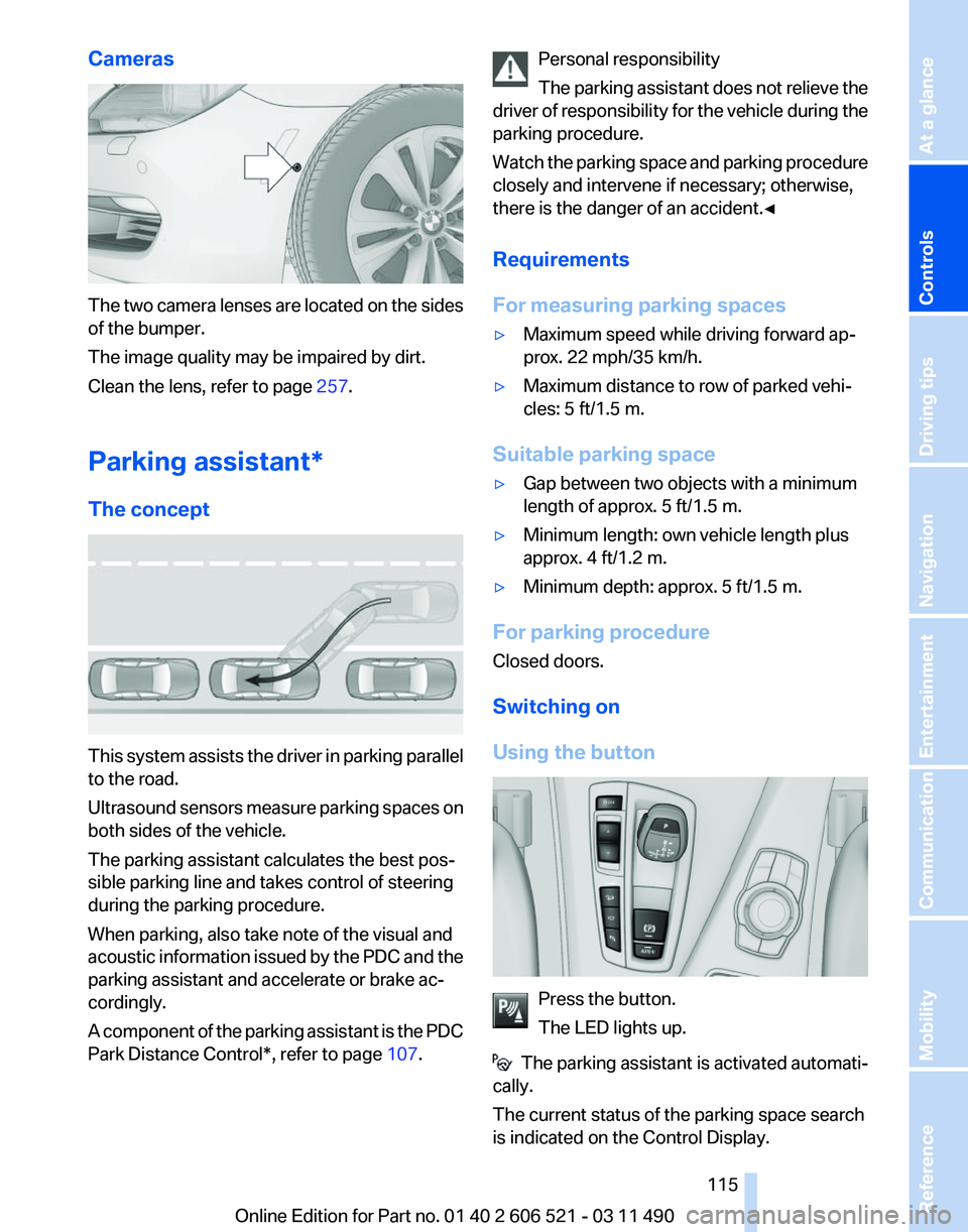
The two camera lenses are located on the sides
of the bumper.
The image quality may be impaired by dirt.
Clean the lens, refer to page
257.
Parking assistant
*
The concept This system assists the driver in parking parallel
to the road.
Ultrasound
sensors measure parking spaces on
both sides of the vehicle.
The parking assistant calculates the best pos‐
sible parking line and takes control of steering
during the parking procedure.
When parking, also take note of the visual and
acoustic information issued by the PDC and the
parking assistant and accelerate or brake ac‐
cordingly.
A component of the parking assistant is the PDC
Park Distance Control*, refer to page 107.Personal responsibility
The
parking assistant does not relieve the
driver of responsibility for the vehicle during the
parking procedure.
Watch the parking space and parking procedure
closely and intervene if necessary; otherwise,
there is the danger of an accident.◀
Requirements
For measuring parking spaces
▷ Maximum speed while driving forward ap‐
prox. 22 mph/35 km/h.
▷ Maximum distance to row of parked vehi‐
cles: 5 ft/1.5 m.
Suitable parking space
▷ Gap between two objects with a minimum
length of approx. 5 ft/1.5 m.
▷ Minimum length: own vehicle length plus
approx. 4 ft/1.2 m.
▷ Minimum depth: approx. 5 ft/1.5 m.
For parking procedure
Closed doors.
Switching on
Using the button Press the button.
The LED lights up.
The parking assistant is activated automati‐
cally.
The current status of the parking space search
is indicated on the Control Display. Seite 115
115Online Edition for Part no. 01 40 2 606 521 - 03 11 490
Reference Mobility Communication Entertainment Navigation Driving tips
Controls At a glance
Page 118 of 282
Limits of ultrasonic measurement
The
detection of objects can reach the physical
limits of ultrasonic measurement, for instance:
▷ With tow bars and trailer hitches.
▷ With thin or wedge-shaped objects.
▷ With elevated, protruding objects such as
ledges or cargo.
▷ With objects with corners and sharp edges.
▷ With objects with a fine surface structure,
such as fences.
The parking assistant may identify parking
spaces that are not suitable for parking.
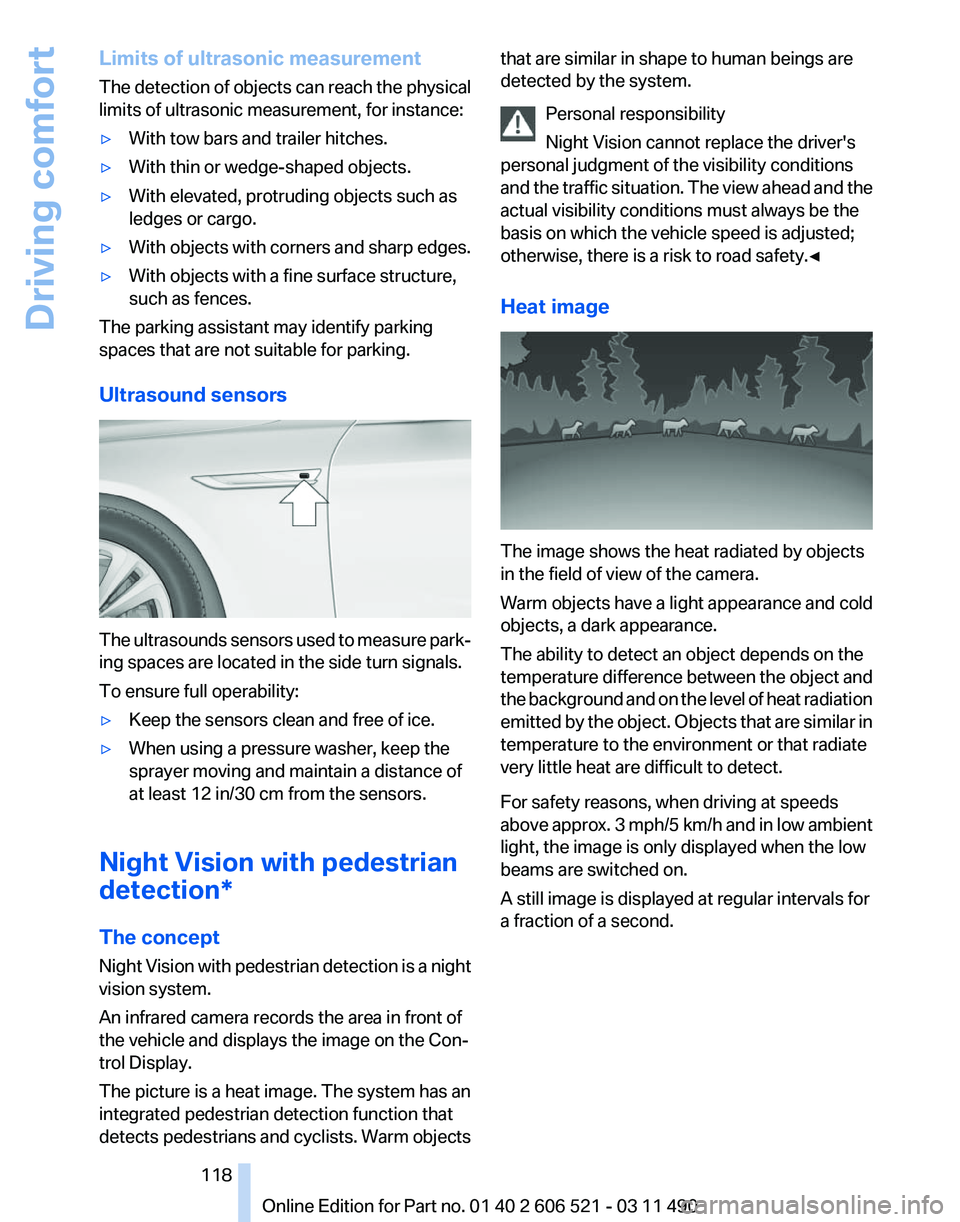
Ultrasound sensors The ultrasounds sensors used to measure park‐
ing spaces are located in the side turn signals.
To ensure full operability:
▷
Keep the sensors clean and free of ice.
▷ When using a pressure washer, keep the
sprayer moving and maintain a distance of
at least 12 in/30 cm from the sensors.
Night Vision with pedestrian
detection*
The concept
Night
Vision with pedestrian detection is a night
vision system.
An infrared camera records the area in front of
the vehicle and displays the image on the Con‐
trol Display.
The picture is a heat image. The system has an
integrated pedestrian detection function that
detects pedestrians and cyclists. Warm objects that are similar in shape to human beings are
detected by the system.
Personal responsibility
Night Vision cannot replace the driver's
personal judgment of the visibility conditions
and
the traffic situation. The view ahead and the
actual visibility conditions must always be the
basis on which the vehicle speed is adjusted;
otherwise, there is a risk to road safety.◀
Heat image The image shows the heat radiated by objects
in the field of view of the camera.
Warm objects have a light appearance and cold
objects, a dark appearance.
The ability to detect an object depends on the
temperature
difference between the object and
the background and on the level of heat radiation
emitted by the object. Objects that are similar in
temperature to the environment or that radiate
very little heat are difficult to detect.
For safety reasons, when driving at speeds
above approx. 3 mph/5 km/h and in low ambient
light, the image is only displayed when the low
beams are switched on.
A still image is displayed at regular intervals for
a fraction of a second. Seite 118
118 Online Edition for Part no. 01 40 2 606 521 - 03 11 490
Driving comfort
Page 119 of 282
Pedestrian detection
The pedestrian detection and warning system
only
operates in darkness and only when a heat
image is displayed.
Warm objects that are similar in shape to human
beings are detected by the system.
People detected by the system are displayed
with a slight yellow hue.
Under good ambient conditions, the pedestrian
detection system operates within a range of ap‐
prox. 50 ft/15 m to approx. 330 ft/100 m. Environmental influences can limit the availabil‐
ity of pedestrian detection.
If
pedestrian detection is not available, a symbol
is displayed in the heat image.
This symbol disappears when the function be‐
comes available again. Warning of people in danger If the system detects a person in the defined
area
in front of the vehicle and if there is the dan‐
ger of a collision with this person, a warning
symbol appears in the Control Display and
Head-up Display*.
Although both the shape and the heat radiation
are analyzed, false warnings cannot be ruled out.
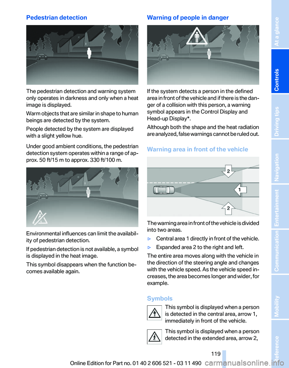
Warning area in front of the vehicle The warning area in front of the vehicle is divided
into two areas.
▷
Central area 1 directly in front of the vehicle.
▷ Expanded area 2 to the right and left.
The entire area moves along with the vehicle in
the direction of the steering angle and changes
with
the vehicle speed. As the vehicle speed in‐
creases, the area becomes longer and wider, for
example.
Symbols
This symbol is displayed when a person
is detected in the central area, arrow 1,
immediately in front of the vehicle.
This symbol is displayed when a person
detected in the extended area, arrow 2, Seite 119
119Online Edition for Part no. 01 40 2 606 521 - 03 11 490
Reference Mobility Communication Entertainment Navigation Driving tips
Controls At a glance
Page 121 of 282
Clean the lens, refer to page
257.
Head-up Display *
The concept This system projects important information into
the driver's field of vision, e.g., the speed.
In this way, the driver can get information with‐
out averting his or her eyes from the road.
Display visibility
The
visibility of the displays in the Head-up Dis‐
play is influenced by:
▷ Certain sitting positions.
▷ Objects on the cover of the Head-up Dis‐
play.
▷ Sunglasses with certain polarization filters.
▷ Wet roads.
▷ Unfavorable light conditions.
If the image is distorted, check the basic set‐
tings.
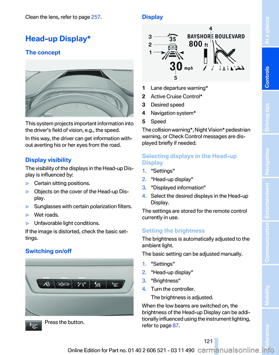
Switching on/off Press the button. Display
1
Lane departure warning*
2 Active Cruise Control*
3 Desired speed
4 Navigation system*
5 Speed
The collision warning*, Night Vision* pedestrian
warning, or Check Control messages are dis‐
played briefly if needed.
Selecting displays in the Head-up
Display
1. "Settings"
2. "Head-up display"
3. "Displayed information"
4. Select the desired displays in the Head-up
Display.
The settings are stored for the remote control
currently in use.
Setting the brightness
The brightness is automatically adjusted to the
ambient light.
The basic setting can be adjusted manually.
1. "Settings"
2. "Head-up display"
3. "Brightness"
4. Turn the controller.
The brightness is adjusted.
When the low beams are switched on, the
brightness
of the Head-up Display can be addi‐
tionally influenced using the instrument lighting,
refer to page 87.
Seite 121
121Online Edition for Part no. 01 40 2 606 521 - 03 11 490
Reference Mobility Communication Entertainment Navigation Driving tips
Controls At a glance
Page 127 of 282
The symbol on the automatic climate control
lights up when the switch-on time is activated. The symbol on the automatic climate control
flashes when the system has been switched on.
The system will only be switched on within the
next 24 hours. After that, it needs to reactivated.
Seite 127
127Online Edition for Part no. 01 40 2 606 521 - 03 11 490
Reference Mobility Communication Entertainment Navigation Driving tips
Controls At a glance
Page 128 of 282
Interior equipment
Integrated universal remote
control*
The concept
This system can replace up to three different
hand-held transmitters for various types of re‐
mote-controlled equipment, such as garage
doors or lighting systems.
The hand-held transmitter signal can be pro‐
grammed on one of the three memory buttons.
The
corresponding device can then be operated
using the programmed memory button.
The LED indicates that a signal is being trans‐
mitted.
When selling the vehicle, delete the stored pro‐
grams for security reasons.
During programming
During programming and before activat‐
ing a device using the universal remote control,
ensure that there are no people, animals, or ob‐
jects in the range of movement of the remote-
controlled device; otherwise, there is a risk of
injury or damage.
Also follow the safety instructions of the hand-
held transmitter.◀
Compatibility
If this symbol is printed on the packaging
or in the instructions of the hand-held
transmitter, the remote-controlled de‐
vice is generally compatible with the universal
remote control.
If you have any questions, please contact:
▷ Your service center.
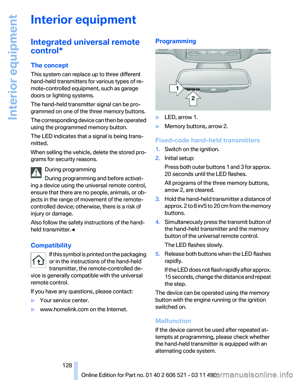
▷ www.homelink.com on the Internet. Programming
▷
LED, arrow 1.
▷ Memory buttons, arrow 2.
Fixed-code hand-held transmitters
1. Switch on the ignition.
2. Initial setup:
Press
both outer buttons 1 and 3 for approx.
20 seconds until the LED flashes.
All programs of the three memory buttons,
arrow 2, are cleared.
3. Hold the hand-held transmitter a distance of
approx.
2 to 8 in/5 to 20 cm from the memory
buttons.
4. Simultaneously press the transmit button of
the hand-held transmitter and the memory
button of the universal remote control.
The LED flashes slowly.
5. Release both buttons when the LED flashes
rapidly.
If
the LED does not flash rapidly after approx.
15 seconds, change the distance and repeat
the step.
The device can be operated using the memory
button with the engine running or the ignition
switched on.
Malfunction
If the device cannot be used after repeated at‐
tempts at programming, please check whether
the hand-held transmitter is equipped with an
alternating code system.
Seite 128
128 Online Edition for Part no. 01 40 2 606 521 - 03 11 490
Interior equipment
Page 129 of 282
To do so:
▷
Read the instructions of the hand-held
transmitter.
▷ Press the memory button of the universal
remote control for an extended period.
If the LED flashes rapidly for a brief period and
then lights up continuously for approx. 2 sec‐
onds, the hand-held transmitter is equipped
with an alternating code system.
In this case, program the memory buttons as
described under Alternating-code hand-held
transmitters.
Alternating-code hand-held
transmitters
Please obtain information on synchronizing the
device
in the operating manual of the device be‐
ing set up.
Programming will be easier with the aid of a sec‐
ond person.
1. Park the vehicle within range of the remote-
controlled device.
2. Program the universal remote control as de‐
scribed above under Fixed-code hand-held
transmitters.
3. Press and hold the programmed button on
the
interior rearview mirror for approx. 5 sec‐
onds until the device to be adjusted is acti‐
vated.
If the device does not become activated,
press and hold the button and watch the
LED:
▷ If the LED lights up continuously, the
programming is completed. The device
should
become activated when the but‐
ton is pressed briefly.
▷ If the LED flashes for approx. 2 seconds
and then lights up continuously, con‐
tinue the programming procedure be‐
ginning with step 4.
4. Locate the button on the receiver of the de‐
vice to be set, e.g., on the drive. 5.
Press the button on the receiver of the de‐
vice
to be set. You have approx. 30 seconds
for the next step.
6. Press the programmed memory button of
the universal remote control three times.
The device can be operated when the engine is
running or the ignition is switched on.
Reassigning individual programs
1. Switch on the ignition.
2. Hold the hand-held transmitter a distance of
approx.
2 to 8 in/5 to 20 cm from the memory
buttons.
3. Press the memory button of the universal
remote control.
4. If the LED flashes slowly after approx.
20 seconds, press the transmit button on
the hand-held transmitter.
5. Release both buttons when the LED flashes
rapidly.
If
the LED does not flash rapidly after approx.
15 seconds, change the distance and repeat
the step.
Deleting all stored programs
Press the left and right memory buttons for ap‐
prox. 20 seconds until the LED flashes rapidly.
All stored programs are deleted.
The programs cannot be deleted individually.
Ashtray/cigarette lighter
*
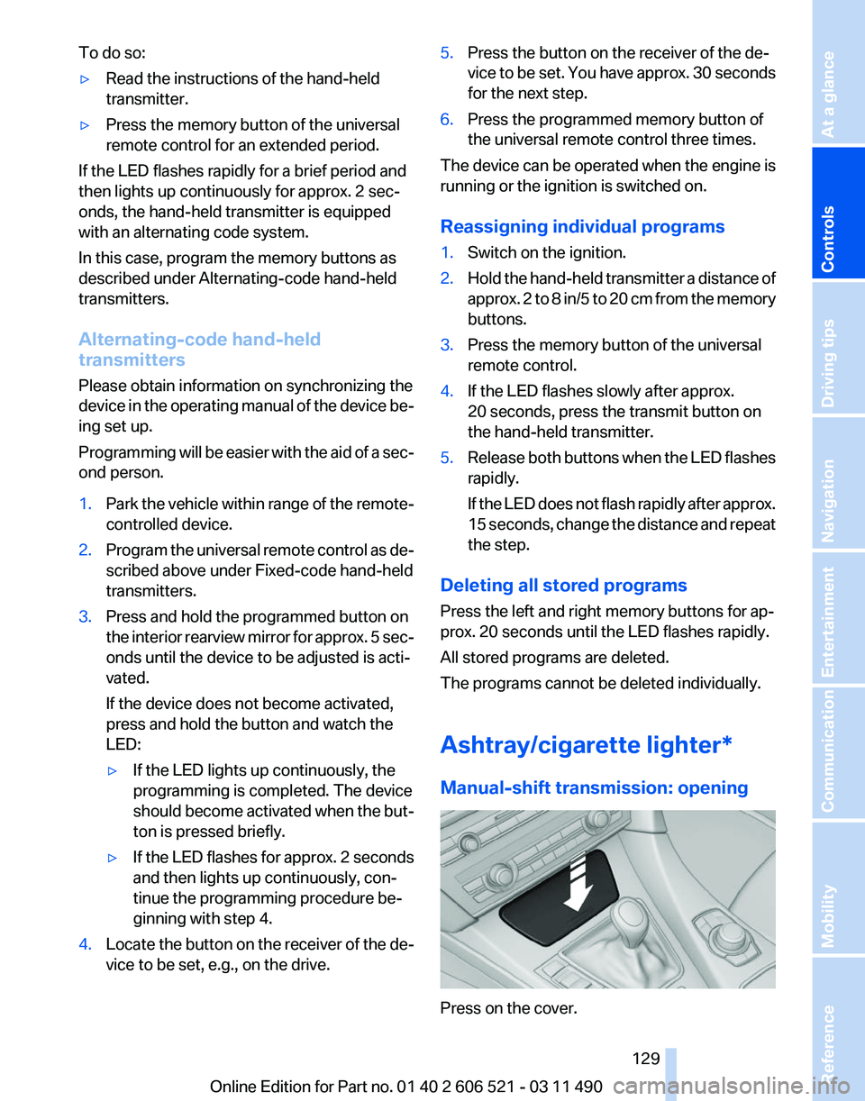
Manual-shift transmission: opening Press on the cover.
Seite 129
129Online Edition for Part no. 01 40 2 606 521 - 03 11 490
Reference Mobility Communication Entertainment Navigation Driving tips
Controls At a glance
Page 130 of 282
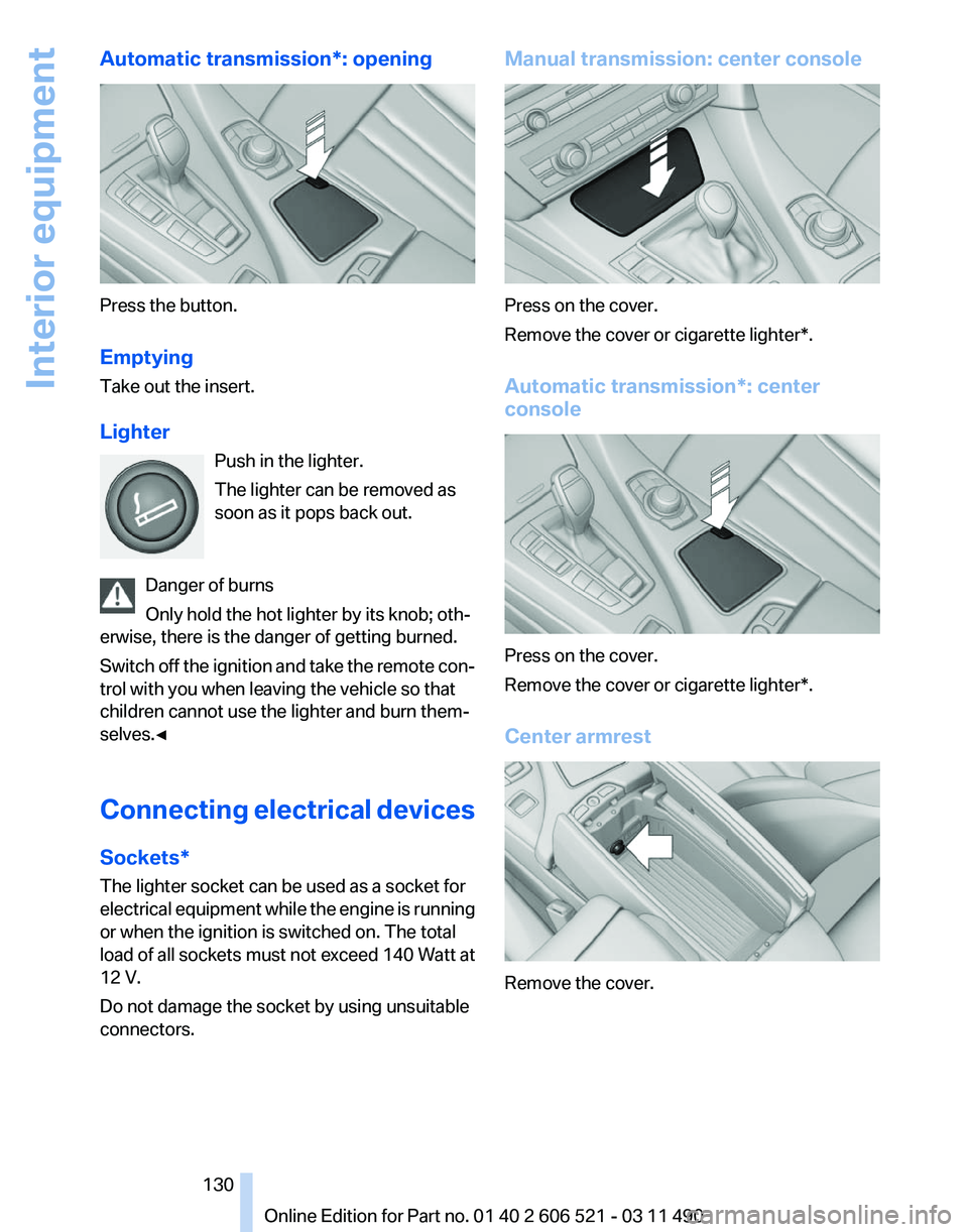
Automatic transmission*: opening
Press the button.
Emptying
Take out the insert.
Lighter
Push in the lighter.
The lighter can be removed as
soon as it pops back out.
Danger of burns
Only hold the hot lighter by its knob; oth‐
erwise, there is the danger of getting burned.
Switch
off the ignition and take the remote con‐
trol with you when leaving the vehicle so that
children cannot use the lighter and burn them‐
selves.◀
Connecting electrical devices
Sockets*
The lighter socket can be used as a socket for
electrical equipment while the engine is running
or when the ignition is switched on. The total
load of all sockets must not exceed 140 Watt at
12 V.
Do not damage the socket by using unsuitable
connectors. Manual transmission: center console
Press on the cover.
Remove the cover or cigarette lighter*.
Automatic transmission
*: center
console Press on the cover.
Remove the cover or cigarette lighter*.
Center armrest
Remove the cover.
Seite 130
130 Online Edition for Part no. 01 40 2 606 521 - 03 11 490
Interior equipment