2012 BMW 650I lights
[x] Cancel search: lightsPage 103 of 282

The rear wheels are turned to the same angle as
the front wheels.
In
critical situations, Integral Active Steering can
specifically steer the front and rear wheels to
stabilize the vehicle before the driver intervenes,
e.g., when braking where road conditions differ
on the left and right sides of the vehicle.
Initializing
In rare cases, it may become necessary to initi‐
alize the Integral Active Steering.
The warning lamp lights up. A Check
Control message is displayed.
1. With the engine running, turn the steering
wheel
all the way to the left and right several
times in a uniform manner until the warning
lamp disappears.
2. Have the system checked if the warning
lamp
does not go out after moving the steer‐
ing wheel approx. 6 times or if the steering
wheel is at an angle.
Using snow chains
Ensure
that the rear axle steering is deactivated
when using snow chains, refer to page 235.
Programs
The system offers two different programs.
The programs can be selected via Dynamic Driv‐
ing Control, refer to page 103.
SPORT
Consistently sporty tuning of the Integral Active
Steering for greater driving agility.
NORMAL
Balanced tuning of the Integral Active Steering
for optimal traveling comfort.
Malfunction
In the event of a malfunction, the steering wheel
must be turned further, while the vehicle re‐
sponds more sensitively to steering wheel
movements in the higher speed range. The stability-enhancing intervention may be de‐
activated.
Proceed cautiously and drive defensively.
Have the system checked.
Dynamic Driving Control*
The concept
Dynamic Driving Control can be used to adjust
the
driving dynamics of the vehicle. Several pro‐
grams are available for this purpose; they can be
activated using the two Dynamic Driving Control
buttons.
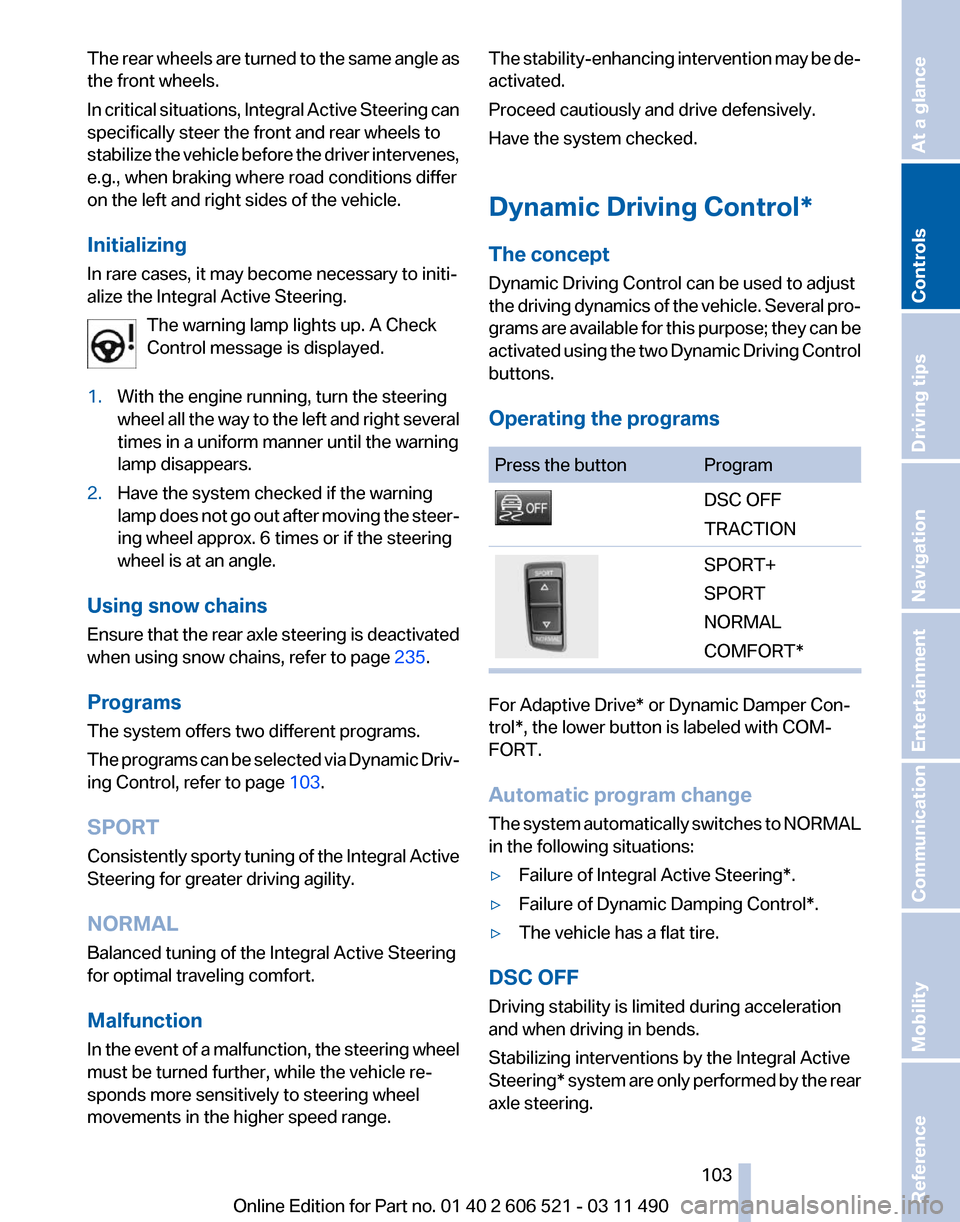
Operating the programs Press the button Program
DSC OFF
TRACTION
SPORT+
SPORT
NORMAL
COMFORT*
For Adaptive Drive* or Dynamic Damper Con‐
trol*, the lower button is labeled with COM‐
FORT.
Automatic program change
The
system automatically switches to NORMAL
in the following situations:
▷ Failure of Integral Active Steering*.
▷ Failure of Dynamic Damping Control*.
▷ The vehicle has a flat tire.
DSC OFF
Driving stability is limited during acceleration
and when driving in bends.
Stabilizing interventions by the
Integral Active
Steering* system are only performed by the rear
axle steering.
Seite 103
103Online Edition for Part no. 01 40 2 606 521 - 03 11 490
Reference Mobility Communication Entertainment Navigation Driving tips
Controls At a glance
Page 104 of 282

To increase vehicle stability, activate DSC again
as soon as possible.
Activating DSC OFF
Press and hold the button, but not lon‐
ger than approx. 10 seconds, until the
indicator lamp for the DSC lights up in the in‐
strument cluster and DSC OFF is displayed in
the tachometer.
The DSC system is switched off.
Deactivating DSC OFF
Press the button.
DSC OFF and the DSC indicator lamp
go out.
Indicator/warning lamps
When DSC OFF is activated, DSC OFF is dis‐
played in the tachometer.
The indicator lamp lights up: DSC OFF
is activated.
TRACTION
Maximum traction on loose road surfaces. DTC
Dynamic Traction Control is switched on. Driv‐
ing stability is limited during acceleration and
when driving in bends.
Activating TRACTION Press the button.
TRACTION
is displayed in the tachom‐
eter.
The DSC indicator lamp in the instrument clus‐
ter lights up.
Deactivating TRACTION
Press the button again.
TRACTION and the DSC indicator lamp
go out.
Indicator/warning lamps
When TRACTION is activated, TRACTION is
displayed in the tachometer. The indicator lamp lights up: TRACTION
is activated.
SPORT+
Sporty driving with optimized chassis and sus‐
pension during limited driving stabilization.
Dynamic Traction Control is switched on.
The driver handles several of the stabilization
tasks.
Activating SPORT+ Press the button repeatedly until
SPORT+ appears in the tachometer
and the DSC indicator lamp lights up in the in‐
strument cluster.
Indicator/warning lamps
SPORT+ is displayed in the instrument cluster.
The indicator lamp lights up: DTC Dy‐
namic Traction Control is activated.
SPORT
Consistently
sporty tuning of the suspension for
greater driving agility with maximum driving sta‐
bilization.
The program can be configured to individual
specifications.
The configuration is stored for the remote con‐
trol currently in use.
Activating SPORT
Press the button repeatedly until
SPORT appears in the tachometer.
Configuring SPORT
When the display is activated on the Control
Display, refer to page 105, the sport program
can be set to individual specifications.
After the sport program is activated, select
"Configure SPORT mode" on the displayed
panel and configure the program.
Optionally, the sport program can be configured
before it is activated: Seite 104
104 Online Edition for Part no. 01 40 2 606 521 - 03 11 490
Driving stability control systems
Page 107 of 282

Change, maintain speed
The rocker switch can be pressed while inter‐
rupted to maintain and store the current speed.
Adapting the desired speed
Adapt the desired speed to the road con‐
ditions
and be ready to brake at all times; other‐
wise, there is the danger of an accident occur‐
ring.◀ Press the rocker switch up or down repeatedly
until the desired speed is set.
If active, the displayed speed is stored and the
vehicle reaches the stored speed if the road is
clear.
▷
Each time the rocker switch is pressed to the
point of resistance, the desired speed in‐
creases or decreases by approx. 1 mph/
1 km/h.
▷ Each time the rocker switch is pressed past
the point of resistance, the desired speed
increases or decreases by a maximum of
5 mph/10 km/h.
▷ Pressing the rocker switch to the resistance
point and holding it accelerates or deceler‐
ates the vehicle without requiring pressure
on
the accelerator. After the rocker switch is
released, the vehicle maintains its final
speed. Pressing the switch beyond the re‐
sistance point causes the vehicle to accel‐
erate more rapidly.
Resuming the desired speed Press the button.
The stored speed is reached and maintained. Displays in the instrument cluster
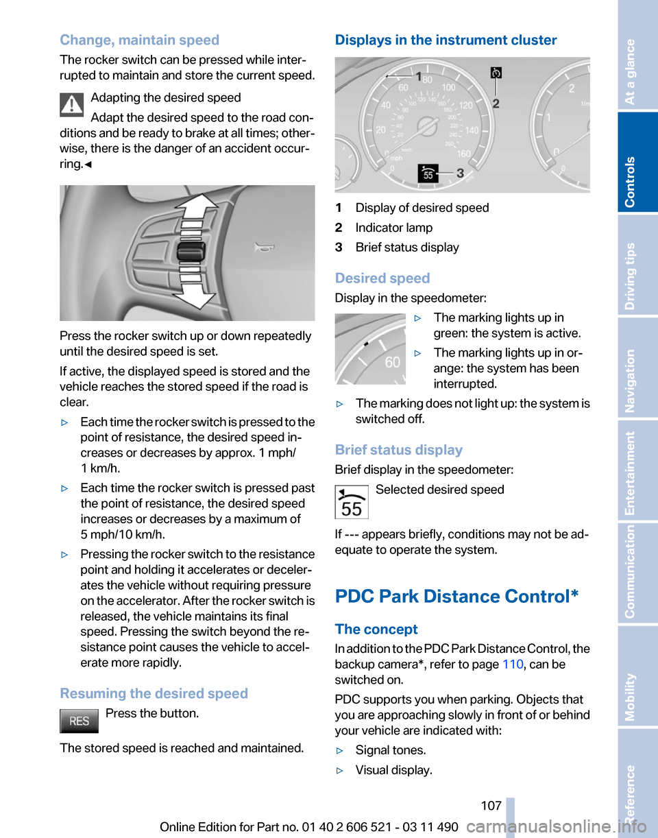
1
Display of desired speed
2 Indicator lamp
3 Brief status display
Desired speed
Display in the speedometer: ▷The marking lights up in
green: the system is active.
▷ The marking lights up in or‐
ange: the system has been
interrupted.
▷ The marking does not light up: the system is
switched off.
Brief status display
Brief display in the speedometer: Selected desired speed
If --- appears briefly, conditions may not be ad‐
equate to operate the system.
PDC Park Distance Control*
The concept
In
addition to the PDC Park Distance Control, the
backup camera*, refer to page 110, can be
switched on.
PDC supports you when parking. Objects that
you are approaching slowly in front of or behind
your vehicle are indicated with:
▷ Signal tones.
▷ Visual display. Seite 107
107Online Edition for Part no. 01 40 2 606 521 - 03 11 490
Reference Mobility Communication Entertainment Navigation Driving tips
Controls At a glance
Page 108 of 282

Measurement
Measurements
are made by ultrasound sensors
in the bumpers.
The range is approx. 6 ft/2 m.
An acoustic warning is first given:
▷ By the front* sensors and the two rear cor‐
ner sensors at approx. 24 in/60 cm.
▷ By the rear middle sensors at approx. 5 ft/
1.50 m.
System limits Check the traffic situation as well
PDC cannot serve as a substitute for the
driver's personal judgment of the traffic situa‐
tion.
Check the traffic situation around the vehi‐
cle with your own eyes. Otherwise, an accident
could result from road users or objects located
outside of the PDC detection range.
Loud noises from outside and inside the vehicle
may prevent you from hearing the PDC's signal
tone.◀
Avoid driving quickly with PDC
Avoid approaching an object quickly.
Avoid driving away quickly while PDC is not yet
active.
For technical reasons, the system may other‐
wise be too late in issuing a warning.◀
Limits of ultrasonic measurement
The detection of objects can reach the physical
limits of ultrasonic measurement, for instance:
▷ With tow bars and trailer hitches.
▷ With thin or wedge-shaped objects.
▷ With low objects.
▷ With objects with corners and sharp edges.
Low objects already displayed, e.g., curbs, can
move
into the blind area of the sensors before or
after a continuous tone sounds.
High, protruding objects such as ledges may not
be detected. False warnings
PDC may issue a warning under the following
conditions even though there is no obstacle
within the detection range:
▷
In heavy rain.
▷ When sensors are very dirty or covered in
ice.
▷ When sensors are covered in snow.
▷ On rough road surfaces.
▷ In large buildings with right angles and
smooth
walls, e.g., in underground garages.
▷ In heavy exhaust.
▷ Due to other ultrasound sources, e.g.,
sweeping machines, high pressure steam
cleaners or neon lights.
Switching on automatically
Select transmission position R with the engine
running.
Switching off automatically
The
system switches off and the LED goes out:
▷ After approx. 160 ft/50 m when driving for‐
ward.
▷ Above approx. 22 mph/36 km/h when driv‐
ing forward.
Switch on the system again if necessary.
Switching on/off manually Press the button.
▷ On: the LED lights up.
▷ Off: the LED goes out. Seite 108
108 Online Edition for Part no. 01 40 2 606 521 - 03 11 490
Driving comfort
Page 110 of 282

▷
Keep the sensors clean and free of ice.
▷ When using a pressure washer, keep the
sprayer moving and maintain a distance of
at least 12 in/30 cm from the sensors.
Surround View*
The concept
Surround View includes the following systems:
▷ Backup camera, refer to page 110.
▷ Side View, refer to page 114.
▷ Top View, refer to page 112.
It assists the driver when parking, maneuvering
and on blind driveways and intersections.
Backup camera*
The concept
The
backup camera provides assistance in park‐
ing and maneuvering backwards. The area be‐
hind the vehicle is shown on the Control Display.
System limits
Check the traffic situation as well
Check the traffic situation around the ve‐
hicle with your own eyes. Otherwise, an accident
could result from road users or objects located
outside the picture area of the backup camera.◀
Detection of objects
High, protruding objects such as ledges
may not be detected by the backup camera.◀
Switching on automatically
Select transmission position R with the engine
running.
The backup camera image is displayed if the
system was switched on via the iDrive.
Switching off automatically
The system switches off and the LED goes out: ▷
After approx. 33 ft/10 m when driving for‐
ward.
▷ Above approx. 9 mph/15 km/h when driving
forward.
Switch on the system again if necessary.
Switching on/off manually Press the button.
▷ On: the LED lights up.
▷ Off: the LED goes out.
The PDC is shown on the Control Display.
Switch
on the backup camera via the iDrive, refer
to page 112.
Assistance functions
Functional requirement
▷ The backup camera is switched on.
▷ The trunk lid is fully closed.
Pathway lines ▷
Can be shown in the backup camera image
when in transmission position R. Seite 110
110 Online Edition for Part no. 01 40 2 606 521 - 03 11 490
Driving comfort
Page 113 of 282

Switching on/off manually
Press the button.
▷ On: the LED lights up.
▷ Off: the LED goes out.
If Top View is displayed, switch on the backup
camera via the iDrive, refer to page 113.
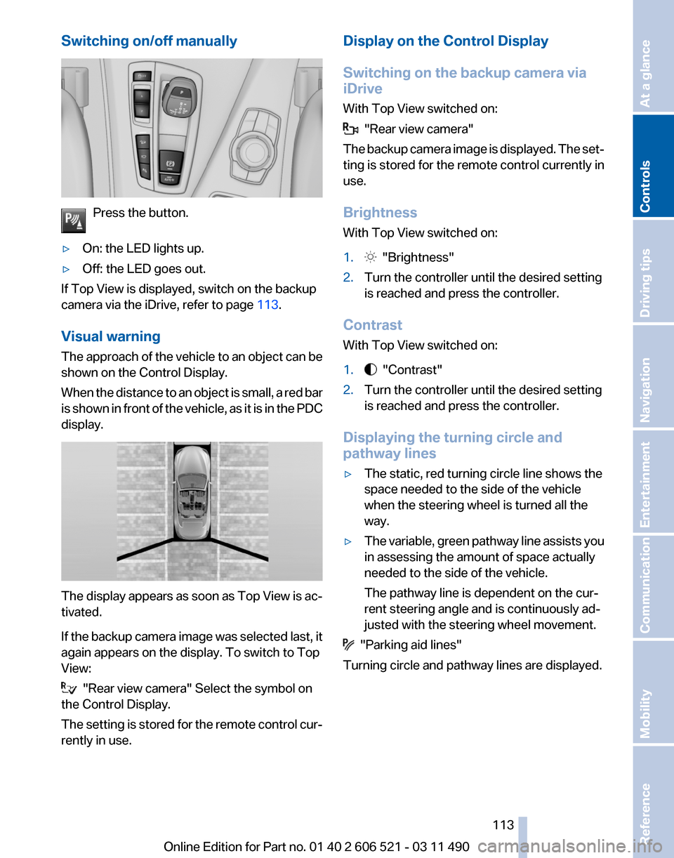
Visual warning
The
approach of the vehicle to an object can be
shown on the Control Display.
When the distance to an object is small, a red bar
is shown in front of the vehicle, as it is in the PDC
display. The display appears as soon as Top View is ac‐
tivated.
If
the backup camera image was selected last, it
again appears on the display. To switch to Top
View: "Rear view camera" Select the symbol on
the Control Display.
The
setting is stored for the remote control cur‐
rently in use. Display on the Control Display
Switching on the backup camera via
iDrive
With Top View switched on:
"Rear view camera"
The
backup camera image is displayed. The set‐
ting is stored for the remote control currently in
use.
Brightness
With Top View switched on:
1. "Brightness"
2. Turn the controller until the desired setting
is reached and press the controller.
Contrast
With Top View switched on:
1. "Contrast"
2. Turn the controller until the desired setting
is reached and press the controller.
Displaying the turning circle and
pathway lines
▷ The static, red turning circle line shows the
space needed to the side of the vehicle
when the steering wheel is turned all the
way.
▷ The variable, green pathway line assists you
in assessing the amount of space actually
needed to the side of the vehicle.
The pathway line is dependent on the cur‐
rent steering angle and is continuously ad‐
justed with the steering wheel movement. "Parking aid lines"
Turning circle and pathway lines are displayed.
Seite 113
113Online Edition for Part no. 01 40 2 606 521 - 03 11 490
Reference Mobility Communication Entertainment Navigation Driving tips
Controls At a glance
Page 115 of 282

Cameras
The two camera lenses are located on the sides
of the bumper.
The image quality may be impaired by dirt.
Clean the lens, refer to page
257.
Parking assistant
*
The concept This system assists the driver in parking parallel
to the road.
Ultrasound
sensors measure parking spaces on
both sides of the vehicle.
The parking assistant calculates the best pos‐
sible parking line and takes control of steering
during the parking procedure.
When parking, also take note of the visual and
acoustic information issued by the PDC and the
parking assistant and accelerate or brake ac‐
cordingly.
A component of the parking assistant is the PDC
Park Distance Control*, refer to page 107.Personal responsibility
The
parking assistant does not relieve the
driver of responsibility for the vehicle during the
parking procedure.
Watch the parking space and parking procedure
closely and intervene if necessary; otherwise,
there is the danger of an accident.◀
Requirements
For measuring parking spaces
▷ Maximum speed while driving forward ap‐
prox. 22 mph/35 km/h.
▷ Maximum distance to row of parked vehi‐
cles: 5 ft/1.5 m.
Suitable parking space
▷ Gap between two objects with a minimum
length of approx. 5 ft/1.5 m.
▷ Minimum length: own vehicle length plus
approx. 4 ft/1.2 m.
▷ Minimum depth: approx. 5 ft/1.5 m.
For parking procedure
Closed doors.
Switching on
Using the button Press the button.
The LED lights up.
The parking assistant is activated automati‐
cally.
The current status of the parking space search
is indicated on the Control Display. Seite 115
115Online Edition for Part no. 01 40 2 606 521 - 03 11 490
Reference Mobility Communication Entertainment Navigation Driving tips
Controls At a glance
Page 127 of 282

The symbol on the automatic climate control
lights up when the switch-on time is activated. The symbol on the automatic climate control
flashes when the system has been switched on.
The system will only be switched on within the
next 24 hours. After that, it needs to reactivated.
Seite 127
127Online Edition for Part no. 01 40 2 606 521 - 03 11 490
Reference Mobility Communication Entertainment Navigation Driving tips
Controls At a glance