2012 BMW 650I CONVERTIBLE warning
[x] Cancel search: warningPage 108 of 282

Measurement
Measurements
are made by ultrasound sensors
in the bumpers.
The range is approx. 6 ft/2 m.
An acoustic warning is first given:
▷ By the front* sensors and the two rear cor‐
ner sensors at approx. 24 in/60 cm.
▷ By the rear middle sensors at approx. 5 ft/
1.50 m.
System limits Check the traffic situation as well
PDC cannot serve as a substitute for the
driver's personal judgment of the traffic situa‐
tion.
Check the traffic situation around the vehi‐
cle with your own eyes. Otherwise, an accident
could result from road users or objects located
outside of the PDC detection range.
Loud noises from outside and inside the vehicle
may prevent you from hearing the PDC's signal
tone.◀
Avoid driving quickly with PDC
Avoid approaching an object quickly.
Avoid driving away quickly while PDC is not yet
active.
For technical reasons, the system may other‐
wise be too late in issuing a warning.◀
Limits of ultrasonic measurement
The detection of objects can reach the physical
limits of ultrasonic measurement, for instance:
▷ With tow bars and trailer hitches.
▷ With thin or wedge-shaped objects.
▷ With low objects.
▷ With objects with corners and sharp edges.
Low objects already displayed, e.g., curbs, can
move
into the blind area of the sensors before or
after a continuous tone sounds.
High, protruding objects such as ledges may not
be detected. False warnings
PDC may issue a warning under the following
conditions even though there is no obstacle
within the detection range:
▷
In heavy rain.
▷ When sensors are very dirty or covered in
ice.
▷ When sensors are covered in snow.
▷ On rough road surfaces.
▷ In large buildings with right angles and
smooth
walls, e.g., in underground garages.
▷ In heavy exhaust.
▷ Due to other ultrasound sources, e.g.,
sweeping machines, high pressure steam
cleaners or neon lights.
Switching on automatically
Select transmission position R with the engine
running.
Switching off automatically
The
system switches off and the LED goes out:
▷ After approx. 160 ft/50 m when driving for‐
ward.
▷ Above approx. 22 mph/36 km/h when driv‐
ing forward.
Switch on the system again if necessary.
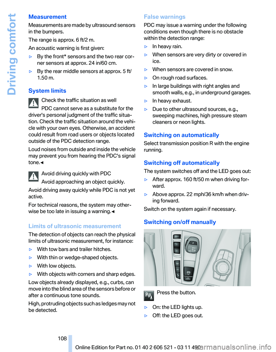
Switching on/off manually Press the button.
▷ On: the LED lights up.
▷ Off: the LED goes out. Seite 108
108 Online Edition for Part no. 01 40 2 606 521 - 03 11 490
Driving comfort
Page 109 of 282

Signal tones
When approaching an object, an intermittent
tone
is sounded that indicates the position of the
object. For example, if an object is detected to
the left rear of the vehicle, a signal tone sounds
from the left rear speaker.
The shorter the distance to the object becomes,
the shorter the intervals.
If the distance to a detected object is less than
approx. 12 in/30 cm, a continuous tone is
sounded.
If objects are located both in front of and behind
the vehicle, an alternating continuous signal is
sounded.
The intermittent tone is interrupted after approx.
3 seconds:
▷ If the vehicle stops in front of an object that
is detected by only one of the corner sen‐
sors.
▷ If moving parallel to a wall.
The signal tone is switched off:
▷ When the vehicle moves away from an ob‐
ject by more than approx. 4 in/10 cm.
▷ When transmission position P is engaged.
Volume
You can set the volume of the PDC signal tone,
refer to page 165.
The
setting is stored for the remote control cur‐
rently in use.
Visual warning
The approach of the vehicle to an object can be
shown on the Control Display. Objects that are
farther away are displayed on the Control Dis‐
play before a signal tone sounds.
A display appears as soon as Park Distance
Control (PDC) is activated.
If the backup camera image was selected last, it
again appears on the display. To switch to PDC:
1. "Rear view camera" Select the symbol
on the Control Display.
2. Press the controller. The setting is stored for the remote control cur‐
rently in use.
Zoom view*
On
the left part of the display screen, the vehicle
is shown enlarged. ▷
Forward gear or transmission position D en‐
gaged: front area of the vehicle.
▷ Reverse gear or transmission position R en‐
gaged: rear area of the vehicle.
Display on the Control Display
Switching
on the backup camera via the
iDrive
With PDC activated: "Rear view camera"
The
backup camera image is displayed. The set‐
ting is stored for the remote control currently in
use.
Malfunction
A Check Control message is displayed. On the Control Display, the areas in front of and
behind the vehicle are shaded. PDC has failed.
Have the system checked.
To ensure full operability:
Seite 109
109Online Edition for Part no. 01 40 2 606 521 - 03 11 490
Reference Mobility Communication Entertainment Navigation Driving tips
Controls At a glance
Page 113 of 282

Switching on/off manually
Press the button.
▷ On: the LED lights up.
▷ Off: the LED goes out.
If Top View is displayed, switch on the backup
camera via the iDrive, refer to page 113.
Visual warning
The
approach of the vehicle to an object can be
shown on the Control Display.
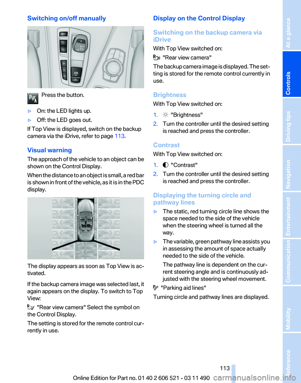
When the distance to an object is small, a red bar
is shown in front of the vehicle, as it is in the PDC
display. The display appears as soon as Top View is ac‐
tivated.
If
the backup camera image was selected last, it
again appears on the display. To switch to Top
View: "Rear view camera" Select the symbol on
the Control Display.
The
setting is stored for the remote control cur‐
rently in use. Display on the Control Display
Switching on the backup camera via
iDrive
With Top View switched on:
"Rear view camera"
The
backup camera image is displayed. The set‐
ting is stored for the remote control currently in
use.
Brightness
With Top View switched on:
1. "Brightness"
2. Turn the controller until the desired setting
is reached and press the controller.
Contrast
With Top View switched on:
1. "Contrast"
2. Turn the controller until the desired setting
is reached and press the controller.
Displaying the turning circle and
pathway lines
▷ The static, red turning circle line shows the
space needed to the side of the vehicle
when the steering wheel is turned all the
way.
▷ The variable, green pathway line assists you
in assessing the amount of space actually
needed to the side of the vehicle.
The pathway line is dependent on the cur‐
rent steering angle and is continuously ad‐
justed with the steering wheel movement. "Parking aid lines"
Turning circle and pathway lines are displayed.
Seite 113
113Online Edition for Part no. 01 40 2 606 521 - 03 11 490
Reference Mobility Communication Entertainment Navigation Driving tips
Controls At a glance
Page 119 of 282

Pedestrian detection
The pedestrian detection and warning system
only
operates in darkness and only when a heat
image is displayed.
Warm objects that are similar in shape to human
beings are detected by the system.
People detected by the system are displayed
with a slight yellow hue.
Under good ambient conditions, the pedestrian
detection system operates within a range of ap‐
prox. 50 ft/15 m to approx. 330 ft/100 m. Environmental influences can limit the availabil‐
ity of pedestrian detection.
If
pedestrian detection is not available, a symbol
is displayed in the heat image.
This symbol disappears when the function be‐
comes available again. Warning of people in danger If the system detects a person in the defined
area
in front of the vehicle and if there is the dan‐
ger of a collision with this person, a warning
symbol appears in the Control Display and
Head-up Display*.
Although both the shape and the heat radiation
are analyzed, false warnings cannot be ruled out.
Warning area in front of the vehicle The warning area in front of the vehicle is divided
into two areas.
▷
Central area 1 directly in front of the vehicle.
▷ Expanded area 2 to the right and left.
The entire area moves along with the vehicle in
the direction of the steering angle and changes
with
the vehicle speed. As the vehicle speed in‐
creases, the area becomes longer and wider, for
example.
Symbols
This symbol is displayed when a person
is detected in the central area, arrow 1,
immediately in front of the vehicle.
This symbol is displayed when a person
detected in the extended area, arrow 2, Seite 119
119Online Edition for Part no. 01 40 2 606 521 - 03 11 490
Reference Mobility Communication Entertainment Navigation Driving tips
Controls At a glance
Page 120 of 282

is moving from the right or left to the central area.
Display in the Head-up Display
*
The warning is simultaneously dis‐
played in the Head-up Display and in the
Control Display. The displayed symbol
can vary with the people detected. For people
located in the central area, the distance to the
person is indicated by the size of the symbol.
System limits
Basic limits
System operation is limited in situations such as
the following:
▷ On steep hills, in steep depressions or in
tight curves.
▷ When the camera is dirty or the protective
glass is damaged.
▷ In heavy fog, rain or snowfall.
▷ At very high external temperatures.
Limits of pedestrian detection
Animals are not detected by the pedestrian de‐
tection
function, even if they are clearly visible in
the image.
Limited pedestrian detection:
▷ When people are fully or partially covered,
especially when their heads are covered.
▷ When people are not in an upright position,
e.g., when lying down.
▷ Cyclists on unconventional bicycles (e.g.,
recumbent bicycles).
▷ After physical damage to the system, e.g.,
after an accident. Activation/deactivation
Press the button.
Display
Settings via iDrive
With Night Vision switched on:
1. Activate Night Vision with pedestrian detec‐
tion.
2. Press the controller.
3. Open the desired menu item.
▷ "Brightness"
▷ "Contrast"
▷ "Pedestrian detection"
The settings are stored for the remote control
currently in use.
Camera Rain, dirt, snow, or ice can impair camera oper‐
ation.
The camera is automatically heated when the
external temperatures are low.
The camera is automatically cleaned together
with the headlamps. Seite 120
120 Online Edition for Part no. 01 40 2 606 521 - 03 11 490
Driving comfort
Page 121 of 282

Clean the lens, refer to page
257.
Head-up Display *
The concept This system projects important information into
the driver's field of vision, e.g., the speed.
In this way, the driver can get information with‐
out averting his or her eyes from the road.
Display visibility
The
visibility of the displays in the Head-up Dis‐
play is influenced by:
▷ Certain sitting positions.
▷ Objects on the cover of the Head-up Dis‐
play.
▷ Sunglasses with certain polarization filters.
▷ Wet roads.
▷ Unfavorable light conditions.
If the image is distorted, check the basic set‐
tings.
Switching on/off Press the button. Display
1
Lane departure warning*
2 Active Cruise Control*
3 Desired speed
4 Navigation system*
5 Speed
The collision warning*, Night Vision* pedestrian
warning, or Check Control messages are dis‐
played briefly if needed.
Selecting displays in the Head-up
Display
1. "Settings"
2. "Head-up display"
3. "Displayed information"
4. Select the desired displays in the Head-up
Display.
The settings are stored for the remote control
currently in use.
Setting the brightness
The brightness is automatically adjusted to the
ambient light.
The basic setting can be adjusted manually.
1. "Settings"
2. "Head-up display"
3. "Brightness"
4. Turn the controller.
The brightness is adjusted.
When the low beams are switched on, the
brightness
of the Head-up Display can be addi‐
tionally influenced using the instrument lighting,
refer to page 87.
Seite 121
121Online Edition for Part no. 01 40 2 606 521 - 03 11 490
Reference Mobility Communication Entertainment Navigation Driving tips
Controls At a glance
Page 238 of 282

Engine oil
General information
The
engine oil consumption is dependent on the
driving style and driving conditions.
Therefore, check the engine oil level after every
refueling using the electronic engine oil level
check.
Checking the oil level
The concept
The oil level is monitored electronically and dis‐
played on the Control Display.
Requirements
▷ The engine must be running and warm after
the vehicle has been driven for at least
6 miles/10 km.
▷ The vehicle is stopped or being driven on a
level roadway.
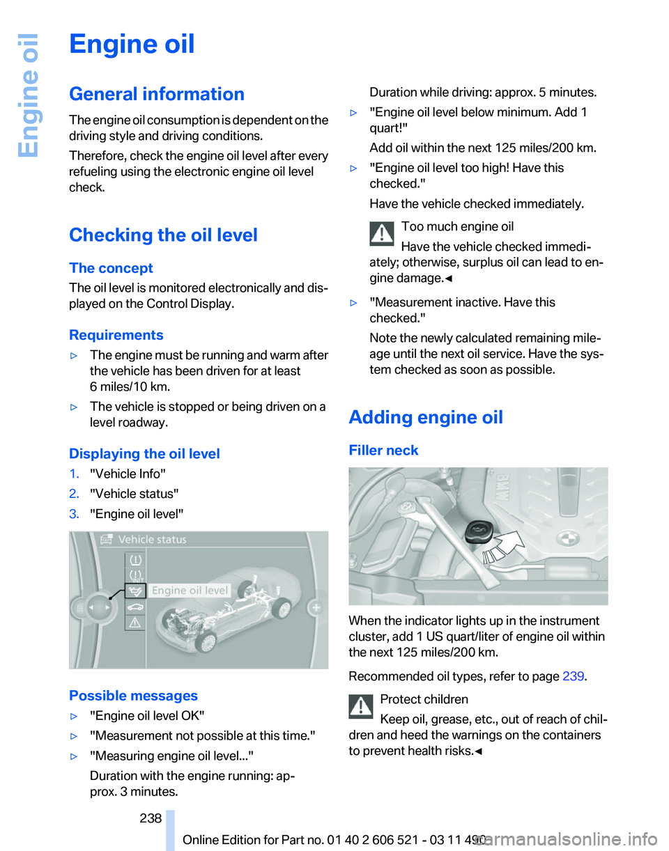
Displaying the oil level
1. "Vehicle Info"
2. "Vehicle status"
3. "Engine oil level" Possible messages
▷
"Engine oil level OK"
▷ "Measurement not possible at this time."
▷ "Measuring engine oil level..."
Duration with the engine running: ap‐
prox. 3 minutes. Duration while driving: approx. 5 minutes.
▷ "Engine oil level below minimum. Add 1
quart!"
Add oil within the next 125 miles/200 km.
▷ "Engine oil level too high! Have this
checked."
Have the vehicle checked immediately.
Too much engine oil
Have the vehicle checked immedi‐
ately; otherwise, surplus oil can lead to en‐
gine damage.
◀ ▷
"Measurement inactive. Have this
checked."
Note the newly calculated remaining mile‐
age until the next oil service. Have the sys‐
tem checked as soon as possible.
Adding engine oil
Filler neck When the indicator lights up in the instrument
cluster, add 1 US quart/liter of engine oil within
the next 125 miles/200 km.
Recommended oil types, refer to page
239.
Protect children
Keep oil, grease, etc., out of reach of chil‐
dren and heed the warnings on the containers
to prevent health risks.◀ Seite 238
238 Online Edition for Part no. 01 40 2 606 521 - 03 11 490Engine oil
Page 241 of 282

Maintenance
BMW Maintenance System
The maintenance system directs you to re‐
quired
maintenance measures and thereby sup‐
ports you in maintaining road safety and the op‐
erational reliability of the vehicle.
Condition Based Service CBS
Sensors and special algorithms take into ac‐
count the driving conditions of your vehicle.
Based on this, Condition Based Service deter‐
mines the maintenance requirements.
The system makes it possible to adapt the
amount of maintenance you need to your user
profile.
Details on the service requirements, refer to
page 81, can be displayed on the Control Dis‐
play.
Service data in the remote control
Information on the required maintenance is con‐
tinuously stored in the remote control. Your
service center will read out this data and suggest
the right array of service procedures for your ve‐
hicle.
Therefore, hand your service specialist the re‐
mote control that you used most recently.
Storage periods
Storage periods during which the vehicle bat‐
tery was disconnected are not taken into ac‐
count.
If this occurs, have a service center update the
time-dependent maintenance procedures,
such as checking brake fluid and, if necessary,
changing the engine oil and the microfilter/acti‐
vated-charcoal filter. Service and Warranty
Information Booklet for US
models and Warranty and
Service Guide Booklet for
Canadian models
Please
consult your Service and Warranty Infor‐
mation Booklet for US models and Warranty and
Service Guide Booklet for Canadian models for
additional information on service requirements.
Maintenance and repair should be performed by
your service center. Make sure to have regular
maintenance procedures recorded in the vehi‐
cle's Service and Warranty Information Booklet
for US models, and in the Warranty and Service
Guide Booklet for Canadian models. These en‐
tries are proof of regular maintenance.
Socket for OBD Onboard
Diagnosis There is an OBD socket on the driver's side for
checking
the primary components in the vehicle
emissions.
Emissions
▷The warning lamp lights up:
Emissions are deteriorating. Have
the
vehicle checked as soon as pos‐
sible.
▷ The warning lamp flashes under cer‐
tain circumstances: Seite 241
241Online Edition for Part no. 01 40 2 606 521 - 03 11 490
Reference
Mobility Communication Entertainment Navigation Driving tips Controls At a glance