2012 BMW 640I COUPE lock
[x] Cancel search: lockPage 71 of 303
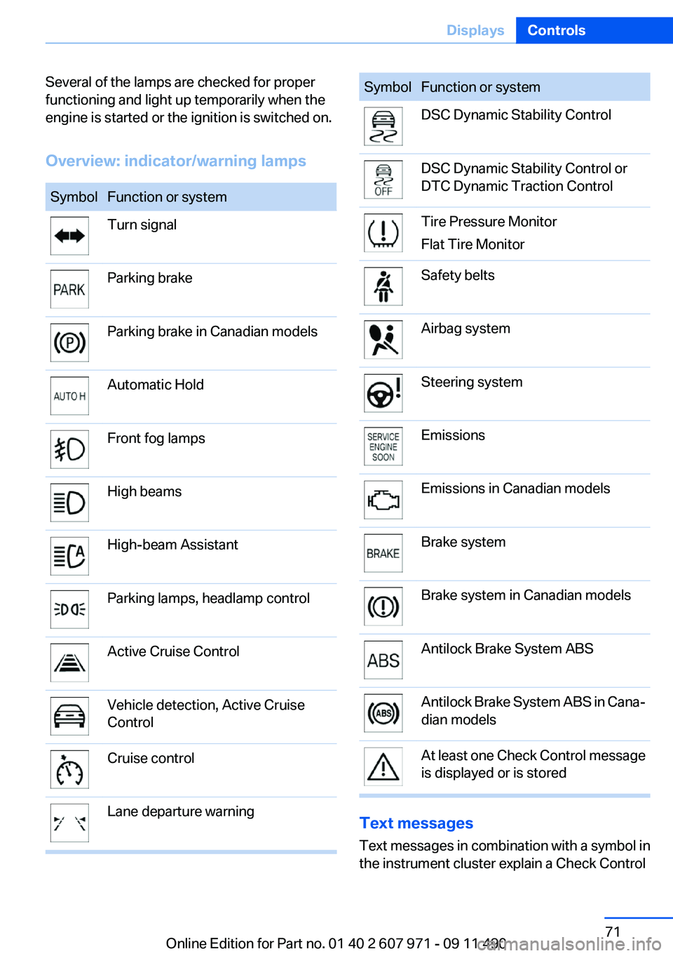
Several of the lamps are checked for proper
functioning and light up temporarily when the
engine is started or the ignition is switched on.
Overview: indicator/warning lampsSymbolFunction or systemTurn signalParking brakeParking brake in Canadian modelsAutomatic HoldFront fog lampsHigh beamsHigh-beam AssistantParking lamps, headlamp controlActive Cruise ControlVehicle detection, Active Cruise
ControlCruise controlLane departure warningSymbolFunction or systemDSC Dynamic Stability ControlDSC Dynamic Stability Control or
DTC Dynamic Traction ControlTire Pressure Monitor
Flat Tire MonitorSafety beltsAirbag systemSteering systemEmissionsEmissions in Canadian modelsBrake systemBrake system in Canadian modelsAntilock Brake System ABSAntilock Brake System ABS in Cana‐
dian modelsAt least one Check Control message
is displayed or is stored
Text messages
Text messages in combination with a symbol in
the instrument cluster explain a Check Control
Seite 71DisplaysControls71
Online Edition for Part no. 01 40 2 607 971 - 09 11 490
Page 81 of 303
LampsVehicle equipment
All standard, country-specific and optional
equipment that is offered in the model series is
described in this chapter. Therefore, equipment
is also described that is not available in a vehicle,
e. g., because of the selected optional equip‐
ment or country variant. This also applies for
safety-related functions and systems.
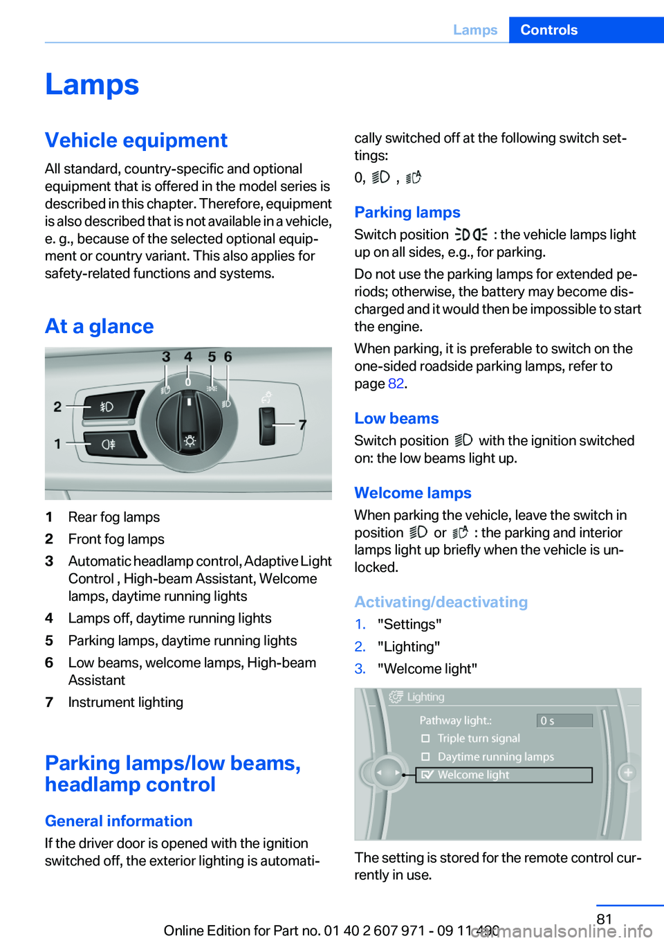
At a glance1Rear fog lamps2Front fog lamps3Automatic headlamp control, Adaptive Light
Control , High-beam Assistant, Welcome
lamps, daytime running lights4Lamps off, daytime running lights5Parking lamps, daytime running lights6Low beams, welcome lamps, High-beam
Assistant7Instrument lighting
Parking lamps/low beams,
headlamp control
General information
If the driver door is opened with the ignition
switched off, the exterior lighting is automati‐
cally switched off at the following switch set‐
tings:
0,
,
Parking lamps
Switch position
: the vehicle lamps light
up on all sides, e.g., for parking.
Do not use the parking lamps for extended pe‐
riods; otherwise, the battery may become dis‐
charged and it would then be impossible to start
the engine.
When parking, it is preferable to switch on the
one-sided roadside parking lamps, refer to
page 82.
Low beams
Switch position
with the ignition switched
on: the low beams light up.
Welcome lamps
When parking the vehicle, leave the switch in
position
or : the parking and interior
lamps light up briefly when the vehicle is un‐
locked.
Activating/deactivating
1."Settings"2."Lighting"3."Welcome light"
The setting is stored for the remote control cur‐
rently in use.
Seite 81LampsControls81
Online Edition for Part no. 01 40 2 607 971 - 09 11 490
Page 87 of 303
Protective action
Airbags are not triggered in every impact situa‐
tion, e.g., in less severe accidents or rear-end
collisions.
Information on how to ensure the optimal
protective effect of the airbags▷Keep at a distance from the airbags.▷Always grasp the steering wheel on the
steering wheel rim, holding your hands at
the 3 o'clock and 9 o'clock positions, to keep
the danger of injury to your hands or arms as
low as possible if the airbag is triggered.▷There should be no people, animals, or ob‐
jects between an airbag and a person.▷Do not use the cover of the front airbag on
the front passenger side as a storage area.▷Keep the dashboard and window on the
front passenger side clear, i.e., do not cover
with adhesive labels or coverings, and do not
attach holders such as for navigation instru‐
ments and mobile phones.▷Make sure that the front passenger is sitting
correctly, i.e., keeps his or her feet and legs
in the footwell; otherwise, leg injuries can
occur if the front airbag is triggered.▷Do not place slip covers, seat cushions or
other objects on the front passenger seat
that are not approved specifically for seats
with integrated side airbags.▷Do not hang pieces of clothing, such as jack‐
ets, over the backrests.▷Make sure that occupants keep their heads
away from the side airbag and do not rest
against the head airbag; otherwise, injuries
can occur if the airbags are triggered.▷Do not remove the airbag restraint system.▷Do not remove the steering wheel.▷Do not apply adhesive materials to the air‐
bag cover panels, cover them or modify
them in any way.▷Never modify either the individual compo‐
nents or the wiring in the airbag system. This
also applies to steering wheel covers, the
dashboard, the seats, the roof pillars and the
sides of the headliner.◀
Even when all instructions are followed closely,
injury from contact with the airbags cannot be
ruled out in certain situations.
The ignition and inflation noise may lead to
short-term and, in most cases, temporary hear‐
ing impairment in sensitive individuals.
In the case of a malfunction, deactivation
and after triggering of the airbags
Do not touch the individual components imme‐
diately after the system has been triggered; oth‐
erwise, there is the danger of burns.
Only have the airbags checked, repaired or dis‐
mantled and the airbag generator scrapped by
your service center or a workshop that has the
necessary authorization for handling explosives.
Non-professional attempts to service the sys‐
tem could lead to failure in an emergency or un‐
desired triggering of the airbag, either of which
could result in injury.◀
Warnings and information on the airbags are
also found on the sun visors.
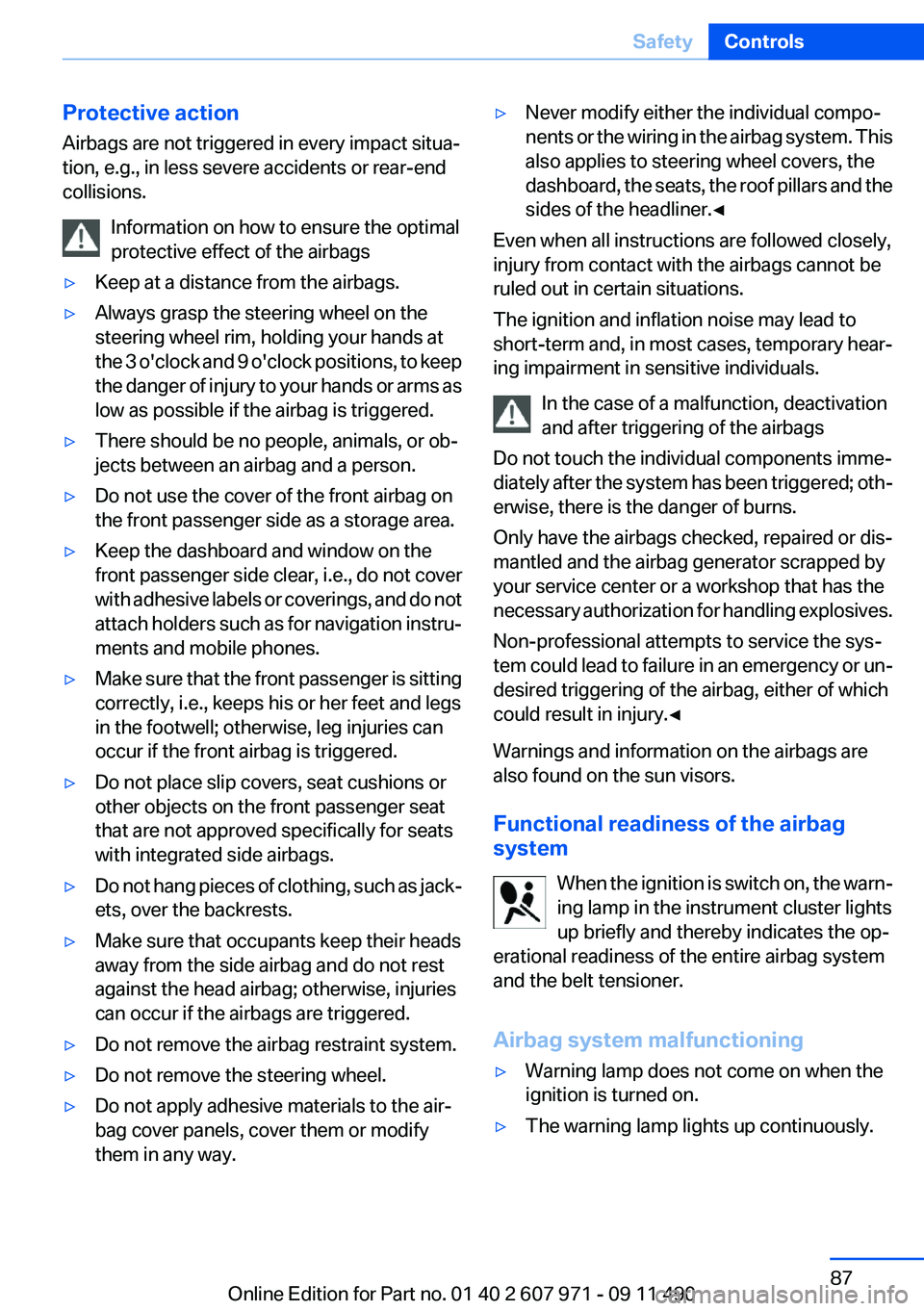
Functional readiness of the airbag
system
When the ignition is switch on, the warn‐
ing lamp in the instrument cluster lights
up briefly and thereby indicates the op‐
erational readiness of the entire airbag system
and the belt tensioner.
Airbag system malfunctioning
▷Warning lamp does not come on when the
ignition is turned on.▷The warning lamp lights up continuously.Seite 87SafetyControls87
Online Edition for Part no. 01 40 2 607 971 - 09 11 490
Page 98 of 303
Driving stability control systemsVehicle equipment
All standard, country-specific and optional
equipment that is offered in the model series is
described in this chapter. Therefore, equipment
is also described that is not available in a vehicle,
e. g., because of the selected optional equip‐
ment or country variant. This also applies for
safety-related functions and systems.
Antilock Brake System ABS
ABS prevents locking of the wheels during brak‐
ing.
The vehicle remains steerable even during full
brake applications, thus increasing active
safety.
ABS is operational every time you start the en‐
gine.
Brake assistant
When you apply the brakes rapidly, this system
automatically produces the maximum braking
force boost. It thus helps to achieve the shortest
possible braking distance during full braking.
This system utilizes all of the benefits provided
by ABS.
Do not reduce the pressure on the brake pedal
for the duration of the full braking.
Adaptive brake assistant
In combination with the Active Cruise Control,
this system ensures that the brakes respond
even more rapidly when braking in critical situa‐
tions. Refer also to Collision warning, refer to
page 112.Drive-off assistant
This system supports driving away on gradients.
The parking brake is not required.1.Hold the vehicle in place with the foot brake.2.Release the foot brake and drive away with‐
out delay.
After the foot brake is released, the vehicle is
held in place for approx. 2 seconds.
Depending on the vehicle load, the vehicle may
roll back slightly.
Driving off without delay
After releasing the foot brake, start driving
without delay, since the drive-off assistant will
not hold the vehicle in place for more than ap‐
prox. 2 seconds and the vehicle will begin rolling
back.◀
DSC Dynamic Stability
Control
The concept
DSC prevents traction loss in the driving wheels
when driving away and accelerating.
DSC also recognizes unstable vehicle condi‐
tions, such as fishtailing or nose-diving. Subject
to physical limits, DSC helps to keep the vehicle
on a steady course by reducing engine speed
and by applying brakes at individual wheels.
Adjust your driving style to the situation
An appropriate driving style is always the
responsibility of the driver.
The laws of physics cannot be repealed, even
with DSC.
Therefore, do not reduce the additional safety
margin by driving in a risky manner.◀
Seite 98ControlsDriving stability control systems98
Online Edition for Part no. 01 40 2 607 971 - 09 11 490
Page 133 of 303
Maximum coolingPress the button.
The system is set to the lowest tem‐
perature, maximum air volume and recirculated-
air mode.
Air flows out of the vents for the upper body re‐
gion. Open them for this purpose.
Air is cooled as quickly as possible:▷At an external temperature of approx. 32 ℉/
0 ℃.▷When the engine is running.
The air volume can be adjusted when the pro‐
gram is active.
Automatic recirculated-air control/
recirculated-air mode
You can respond to unpleasant odors or pollu‐
tants in the immediate environment by tempo‐
rarily suspending the supply of outside air. The
system then recirculates the air currently within
the vehicle.
Press the button repeatedly to select
an operating mode:
▷LEDs off: outside air flows in continuously.▷Left LED on, automatic recirculated-air con‐
trol: a sensor detects pollutants in the out‐
side air and controls the shut-off automati‐
cally.▷Right LED on, recirculated-air mode: the
supply of outside air into the vehicle is per‐
manently blocked.
If the windows are fogged over, switch off the
recirculated-air mode and press the AUTO but‐
ton on the driver's side to utilize the condensa‐
tion sensor. Make sure that air can flow onto the
windshield.
Continuous recirculated-air mode
The recirculated-air mode should not be
used for an extended period of time, as the air
quality inside the vehicle deteriorates steadily. ◀
Cooling function
The passenger compartment can only be
cooled with the engine running.
Press the button.
The air is cooled and dehumidified and
– depending on the temperature setting –
warmed again.
Depending on the weather, the windshield may
fog up briefly when the engine is started.
The cooling function is switched on automati‐
cally with the AUTO program.
When using the automatic climate control, con‐
densation water, refer to page 148, develops
that exits underneath the vehicle.
Rear window defroster Press the button.
The rear window defroster switches off
automatically after a certain period of time.
ALL program Press the button.
Current settings on the driver's side for
the temperature, air volume, air distribution, and
AUTO program are transferred to the front pas‐
senger side.
The program is switched off if the settings on
the front passenger side are changed.
Residual heat
The heat stored in the engine is used to heat the
interior.
Functional requirement▷Up to 20 minutes after the engine has been
switched off.▷Warm engine.▷The battery is sufficiently charged.▷External temperature below 77 ℉/25 ℃.Seite 133Climate controlControls133
Online Edition for Part no. 01 40 2 607 971 - 09 11 490
Page 142 of 303

▷Do not use force when plugging the con‐
nector into the USB interface.▷Do not connect devices such as fans or
lamps to the USB interface.▷Do not connect USB hard drives.▷Do not use the USB interface to recharge
external devices.
Center armrest
Opening
A storage compartment is located in the center
armrest between the front seats.
Press the buttons next to the lock.
Locking the storage compartment
The storage compartment in the armrest can be
locked with an integrated key to separately se‐
cure the trunk lid, refer to page 38, for example.
After the storage compartment is locked, the re‐
mote control can be handed out without the
integrated key, refer to page 30, for instance at
a hotel.
This prevents access to the storage compart‐
ment and to the cargo area.
Connection for an external audio
device
This can be used to connect an external audio
device, such as an MP3 player.
▷AUX-IN port, refer to page 199.▷USB audio interface, refer to page 199.
Cupholders
Notes Shatter-proof containers and no hot
drinks
Use light and shatter-proof containers and do
not transport hot drinks. Otherwise, there is the
increased danger of injury in an accident.◀
Unsuitable containers
Do not forcefully push unsuitable contain‐
ers into the cupholders. This may result in dam‐
age.◀
Seite 142ControlsStorage compartments142
Online Edition for Part no. 01 40 2 607 971 - 09 11 490
Page 143 of 303
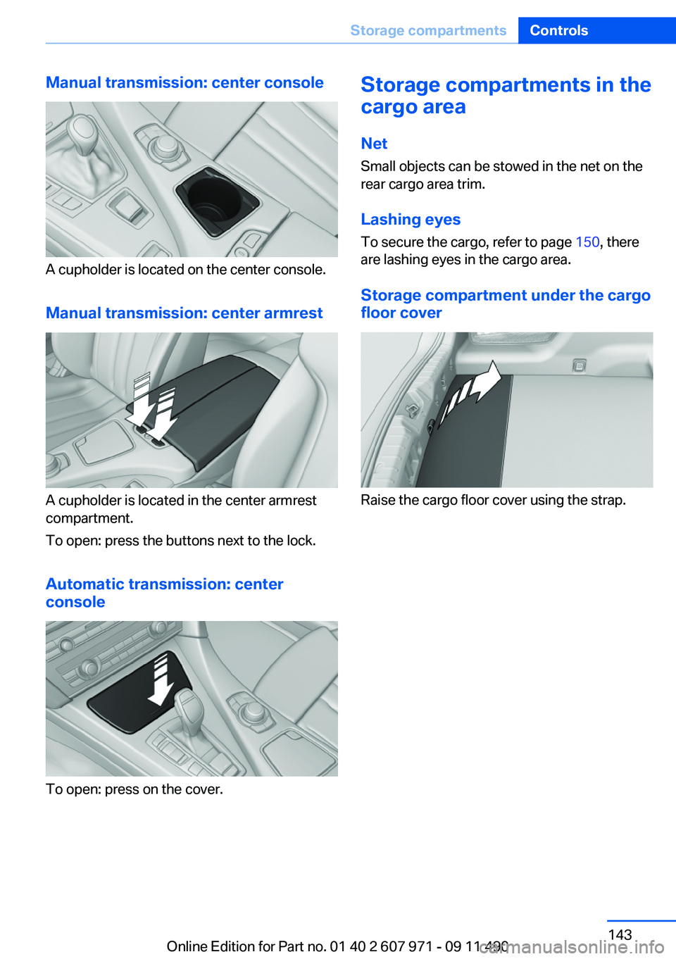
Manual transmission: center console
A cupholder is located on the center console.
Manual transmission: center armrest
A cupholder is located in the center armrest
compartment.
To open: press the buttons next to the lock.
Automatic transmission: center
console
To open: press on the cover.
Storage compartments in the
cargo area
Net
Small objects can be stowed in the net on the
rear cargo area trim.
Lashing eyes
To secure the cargo, refer to page 150, there
are lashing eyes in the cargo area.
Storage compartment under the cargo
floor cover
Raise the cargo floor cover using the strap.
Seite 143Storage compartmentsControls143
Online Edition for Part no. 01 40 2 607 971 - 09 11 490
Page 168 of 303
Resuming the original route
If the route section should no longer be by‐
passed:1."Navigation"2."Route information"3."New route for:"4."Remove blocking"
Gas station recommendation
The remaining range is calculated, and if nec‐
essary gas stations along the route are dis‐
played.
1."Navigation"2."Route information"3."Recommended refuel"
A list of the gas stations is displayed.4.Highlight a gas station.
The position of the gas station is displayed
on the split screen.5.Select the gas station.6. Select the symbol.7."Start guidance": destination guidance to
the selected gas station is started.
"Add as another destination": the gas sta‐
tion is added to the route.
Switching spoken instructions on/off
The setting is stored for the remote control cur‐
rently in use.
1."Navigation"2."Map"3. "Voice instructions"
Repeating spoken instructions
1."Navigation"2."Map"3. Highlight the symbol.4.Press the controller twice.Volume of spoken instructions
Turn the volume button while giving an instruc‐
tion until the desired volume is set.
Saving the spoken instructions on the
programmable memory buttons
The function for switching the spoken instruc‐
tions on/off can be stored on a programmable
memory button, refer to page 20, for quick ac‐
cess.
Map view
Selecting the map view1."Navigation"2."Map"
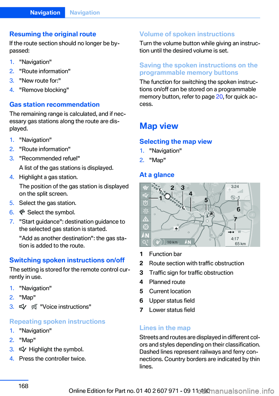
At a glance
1Function bar2Route section with traffic obstruction3Traffic sign for traffic obstruction4Planned route5Current location6Upper status field7Lower status field
Lines in the map
Streets and routes are displayed in different col‐
ors and styles depending on their classification.
Dashed lines represent railways and ferry con‐
nections. Country borders are indicated by thin
lines.
Seite 168NavigationNavigation168
Online Edition for Part no. 01 40 2 607 971 - 09 11 490