Page 13 of 282
High-beam Assistant* 86
Roadside parking lamps 85
Computer 76
9 Steering wheel buttons, left Store speed* 106
Resume speed 107
Cruise control on/off, inter‐
rupt 106
10 Instrument cluster 14
11 Steering wheel buttons, right Entertainment source
Volume Voice activation* 25
Telephone* 196
12 Steering column stalk, right Windshield wipers 69
Rain sensor*
70 Clean the windshields and head‐
lamps* 70
13 Start/stop the engine and switch
the ignition on/off 66
14 Horn
15 Steering wheel heating* 61
16 Adjust the steering wheel
61
17 Unlocking the hood
18 Open the trunk lid
40
Seite 13
13Online Edition for Part no. 01 40 2 606 521 - 03 11 490
Reference Mobility Communication Entertainment Navigation Driving tips Controls
At a glance
Page 14 of 282
Instrument cluster
1
Fuel gauge 74
2 Speedometer
3 Indicator/warning lamps 14
4 Tachometer 75
5 Engine oil temperature 756
External temperature 75
7 Electronic displays 16
8 Miles, trip miles 76
9 Clock 79
10 Reset miles 76
Indicator/warning lamps
Instrument cluster The indicator and warning lamps can light up in
a variety of combinations and colors.
Several of the lamps are checked for proper
functioning
when the engine is started or the ig‐
nition is switched on, and light up briefly in the
process. Overview: indicator/warning lamps Symbol Function or system
Turn signal
Parking brake
Parking brake in Canadian models
Automatic Hold*
Front fog lamps* Seite 14
14 Online Edition for Part no. 01 40 2 606 521 - 03 11 490
Cockpit
Page 15 of 282

Symbol Function or system
High beams
High-beam Assistant*
Parking lamps, headlamp control
Cruise control*
Lane departure warning*
DSC Dynamic Stability Control
DSC Dynamic Stability Control or
DTC Dynamic Traction Control
Tire Pressure Monitor*
Flat Tire Monitor
Safety belts
Airbag system
Steering system Symbol Function or system
Emissions
Brake system
Brake system in Canadian models
Antilock Brake System ABS
Antilock Brake System ABS in Cana‐
dian models
Text messages
Text
messages in combination with a symbol in
the instrument cluster explain a Check Control
message and the meaning of the indicator and
warning lamps.
Supplementary text messages
Additional information on the Control Display,
e.g., on the cause of a malfunction or the re‐
quired action, can be called up via Check Con‐
trol, refer to page 82.
The text of urgent messages is displayed auto‐
matically.
Seite 15
15Online Edition for Part no. 01 40 2 606 521 - 03 11 490
Reference Mobility Communication Entertainment Navigation Driving tips Controls
At a glance
Page 17 of 282
All around the center console
1
All around the interior rearview mir‐
ror 18
2 Control Display 19
3 Glove compartment 132
4 Air vent 126
5 Hazard warning system 248
Central locking system 39
6 Radio 166
CD/multimedia 173
7 Automatic climate control 123
8 Controller with buttons 19
9 Parking brake
67 Automatic Hold*
67 10 Opening and closing the converti‐
ble top
46
11 PDC Park Distance Con‐
trol* 107
Top View* 112
Backup camera* 110
Parking assistant* 115
Side View* 114
12 Dynamic Driving Control* 103
DSC Dynamic Stability Con‐
trol 101
13 Transmission selector lever
Seite 17
17Online Edition for Part no. 01 40 2 606 521 - 03 11 490
Reference Mobility Communication Entertainment Navigation Driving tips Controls
At a glance
Page 21 of 282

White arrows pointing to the left or right indicate
that additional panels can be opened.
View of an opened menu
When
a menu is opened, it generally opens with
the panel that was last selected in that menu. To
display the first panel of a menu:
▷ Move the controller to the left repeatedly
until the first panel is displayed.
▷ Press the menu button on the controller
twice.
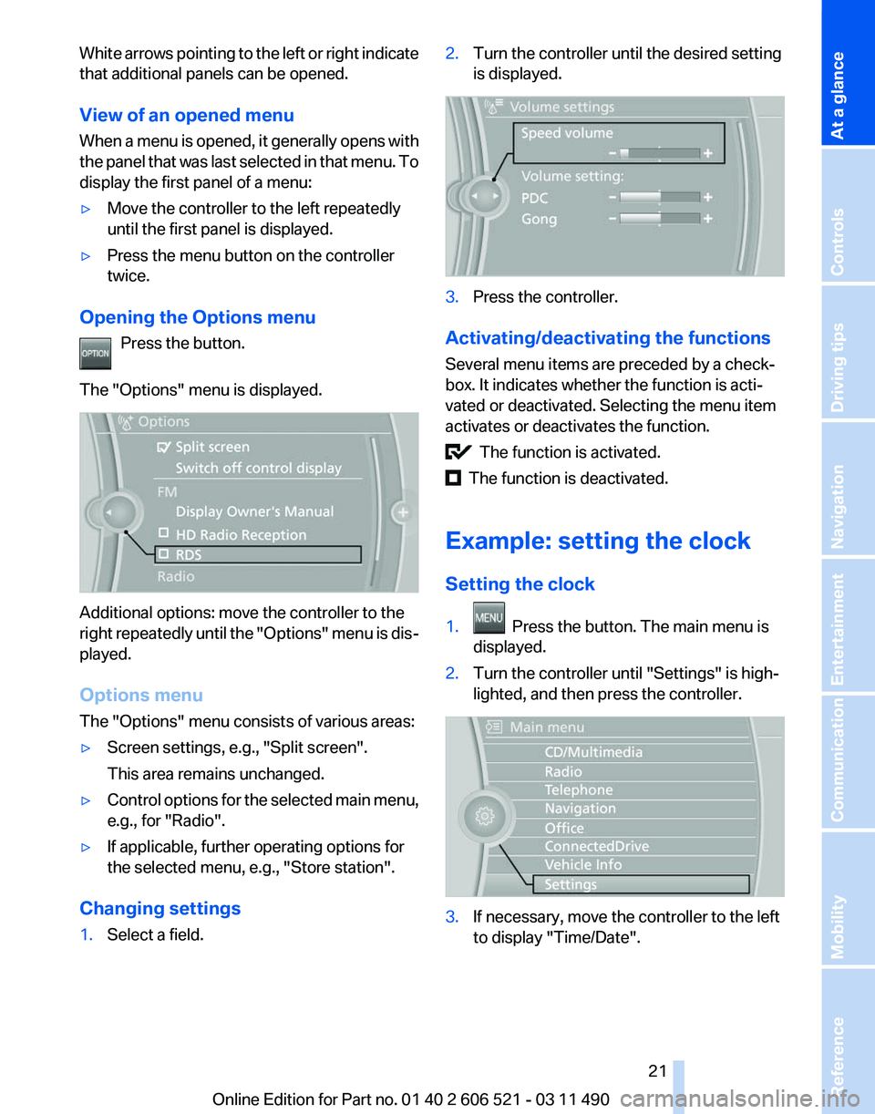
Opening the Options menu Press the button.
The "Options" menu is displayed. Additional options: move the controller to the
right
repeatedly until the "Options" menu is dis‐
played.
Options menu
The "Options" menu consists of various areas:
▷ Screen settings, e.g., "Split screen".
This area remains unchanged.
▷ Control options for the selected main menu,
e.g., for "Radio".
▷ If applicable, further operating options for
the selected menu, e.g.,
"Store station".
Changing settings
1. Select a field. 2.
Turn the controller until the desired setting
is displayed. 3.
Press the controller.
Activating/deactivating the functions
Several menu items are preceded by a check‐
box. It indicates whether the function is acti‐
vated or deactivated. Selecting the menu item
activates or deactivates the function. The function is activated.
The function is deactivated.
Example: setting the clock
Setting the clock
1. Press the button. The main menu is
displayed.
2. Turn the controller until "Settings" is high‐
lighted, and then press the controller. 3.
If necessary, move the controller to the left
to display "Time/Date"
.
Seite 21
21Online Edition for Part no. 01 40 2 606 521 - 03 11 490
Reference Mobility Communication Entertainment Navigation Driving tips Controls
At a glance
Page 22 of 282

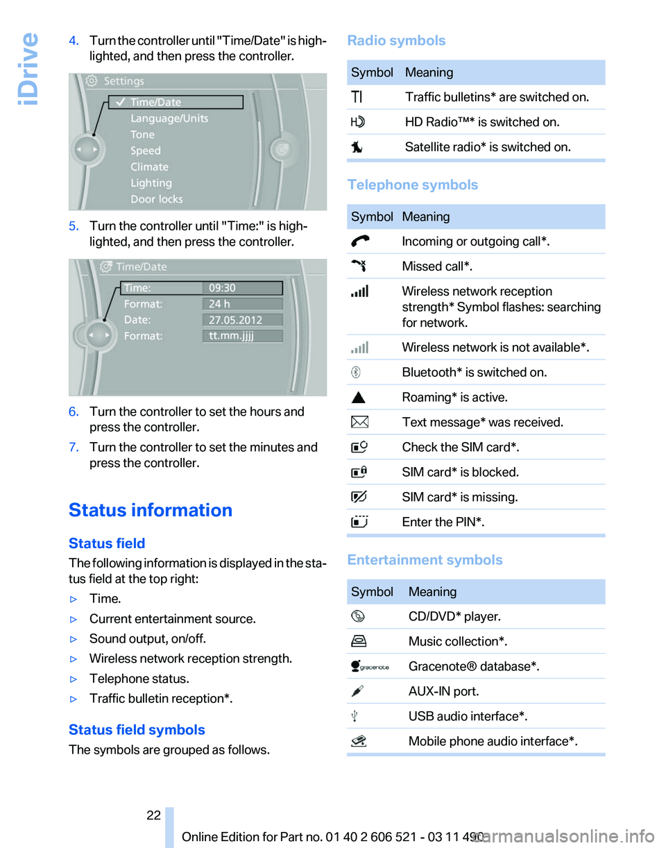
4.
Turn the controller until "Time/Date" is high‐
lighted, and then press the controller. 5.
Turn the controller until "Time:" is high‐
lighted, and then press the controller. 6.
Turn the controller to set the hours and
press the controller.
7. Turn the controller to set the minutes and
press the controller.
Status information
Status field
The
following information is displayed in the sta‐
tus field at the top right:
▷ Time.
▷ Current entertainment source.
▷ Sound output, on/off.
▷ Wireless network reception strength.
▷ Telephone status.
▷ Traffic bulletin reception*.
Status field symbols
The symbols are grouped as follows. Radio symbols Symbol Meaning
Traffic bulletins* are switched on.
HD Radio™* is switched on.
Satellite radio* is switched on.
Telephone symbols
Symbol Meaning
Incoming or outgoing call*.
Missed call*.
Wireless network reception
strength*
Symbol flashes: searching
for network. Wireless network is not available*.
Bluetooth* is switched on.
Roaming* is active.
Text message* was received.
Check the SIM card*.
SIM card* is blocked.
SIM card* is missing.
Enter the PIN*.
Entertainment symbols
Symbol Meaning
CD/DVD* player.
Music collection*.
Gracenote® database*.
AUX-IN port.
USB audio interface*.
Mobile phone audio interface*. Seite 22
22 Online Edition for Part no. 01 40 2 606 521 - 03 11 490
iDrive
Page 32 of 282

Opening and closing
Remote control/key
Buttons on the remote control
1
Unlocking
2 Locking
3 Trunk lid
4 Panic mode*, headlamp courtesy delay fea‐
ture
General information
The vehicle is supplied with two remote controls
with keys.
Every remote control contains a replaceable
battery.
The settings called up and implemented when
the vehicle is unlocked depend on which remote
control is used to unlock the vehicle, Personal
Profile, refer to page 33.
In addition, information about service require‐
ments is stored in the remote control, Service
data in the remote control, refer to page 241.Integrated key Press the button on the back of the remote con‐
trol, arrow 1, and pull out the key, arrow 2.
The integrated key fits the following locks:
▷
Driver's door.
▷ Storage compartment in the center armrest.
The storage compartment contains a switch for
the hotel function, refer to page 39.
Replacing the battery 1.
Take the integrated key out of the remote
control.
2. Push in the catch with the key, arrow 1.
3. Remove the cover of the battery compart‐
ment; see arrow 2.
4. Insert a battery of the same type with the
positive side facing upwards.
5. Press the cover closed.
Take the used battery to a recycling cen‐
ter or to your service center. Seite 32
32 Online Edition for Part no. 01 40 2 606 521 - 03 11 490
Opening and closing
Page 33 of 282

New remote controls
You can obtain new remote controls from your
service center.
Loss of the remote controls
Lost remote controls can be blocked by your
service center.
Emergency
detection of remote control
It is possible to switch on the ignition or start the
engine in situations such as the following:
▷ Interference of radio transmission to remote
control by external sources.
▷ Discharged battery in the remote control.
A Check Control message is displayed if an at‐
tempt is made to switch on the ignition or start
the engine.
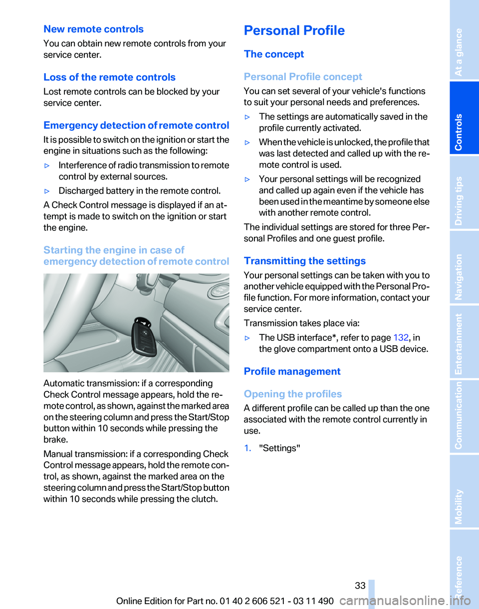
Starting the engine in case of
emergency
detection of remote controlAutomatic transmission: if a corresponding
Check Control message appears, hold the re‐
mote
control, as shown, against the marked area
on the steering column and press the Start/Stop
button within 10 seconds while pressing the
brake.
Manual transmission: if a corresponding Check
Control message appears, hold the remote con‐
trol, as shown, against the marked area on the
steering column and press the Start/Stop button
within 10 seconds while pressing the clutch. Personal Profile
The concept
Personal Profile concept
You can set several of your vehicle's functions
to suit your personal needs and preferences.
▷
The settings are automatically saved in the
profile currently activated.
▷ When the vehicle is unlocked, the profile that
was last detected and called up with the re‐
mote control is used.
▷ Your personal settings will be recognized
and called up again even if the vehicle has
been
used in the meantime by someone else
with another remote control.
The individual settings are stored for three Per‐
sonal Profiles and one guest profile.
Transmitting the settings
Your
personal settings can be taken with you to
another vehicle equipped with the Personal Pro‐
file function. For more information, contact your
service center.
Transmission takes place via:
▷ The USB interface*, refer to page 132, in
the glove compartment onto a USB device.
Profile management
Opening the profiles
A
different profile can be called up than the one
associated with the remote control currently in
use.
1. "Settings"
Seite 33
33Online Edition for Part no. 01 40 2 606 521 - 03 11 490
Reference Mobility Communication Entertainment Navigation Driving tips
Controls At a glance