2012 BMW 640I CONVERTIBLE rear entertainment
[x] Cancel search: rear entertainmentPage 123 of 282
Climate control
Automatic climate control
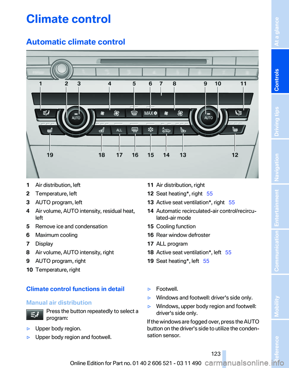
1
Air distribution, left
2 Temperature, left
3 AUTO program, left
4 Air volume, AUTO intensity, residual heat,
left
5 Remove ice and condensation
6 Maximum cooling
7 Display
8 Air volume, AUTO intensity, right
9 AUTO program, right
10 Temperature, right 11
Air distribution, right
12 Seat heating*, right 55
13 Active seat ventilation*, right 55
14 Automatic recirculated-air control/recircu‐
lated-air mode
15 Cooling function
16 Rear window defroster
17 ALL program
18 Active seat ventilation*, left 55
19 Seat heating*, left 55
Climate control functions in detail
Manual air distribution Press the button repeatedly to select a
program:
▷ Upper body region.
▷ Upper body region and footwell. ▷
Footwell.
▷ Windows and footwell: driver's side only.
▷ Windows, upper body region and footwell:
driver's side only.
If the windows are fogged over, press the AUTO
button on the driver's side to utilize the conden‐
sation sensor.
Seite 123
123Online Edition for Part no. 01 40 2 606 521 - 03 11 490
Reference Mobility Communication Entertainment Navigation Driving tips
Controls At a glance
Page 125 of 282
Automatic recirculated-air control/
recirculated-air mode
You can respond to unpleasant odors or pollu‐
tants in the immediate environment by tempo‐
rarily suspending the supply of outside air. The
system
then recirculates the air currently within
the vehicle.
Press the button repeatedly to select
an operating mode:
▷ LEDs off: outside air flows in continuously.
▷ Left LED on, automatic recirculated-air con‐
trol: a sensor detects pollutants in the out‐
side air and controls the shut-off automati‐
cally.
▷ Right LED on, recirculated-air mode: the
supply of outside air into the vehicle is per‐
manently blocked.
If the windows are fogged over, switch off the
recirculated-air
mode and press the AUTO but‐
ton on the driver's side to utilize the condensa‐
tion sensor. Make sure that air can flow onto the
windshield.
Continuous recirculated-air mode
The recirculated-air mode should not be
used for an extended period of time, as the air
quality inside the vehicle deteriorates steadily.◀
Cooling function
The passenger compartment can only be
cooled with the engine running.
Press the button.
The air is cooled and dehumidified and
– depending on the temperature setting –
warmed again.
Depending on the weather, the windshield may
fog up briefly when the engine is started.
The cooling function is switched on automati‐
cally with the AUTO program.
When using the automatic climate control, con‐
densation water, refer to page 140, develops
that exits underneath the vehicle. Rear window defroster
Press the button.
The
rear window defroster switches off
automatically after a certain period of time.
The rear window defroster is only active when
the rear window is closed.
ALL program
Press the button.
Current settings on the driver's side for
the temperature, air volume, air distribution, and
AUTO program are transferred to the front pas‐
senger side.
The program is switched off if the settings on
the front passenger side are changed.
Residual heat
The heat stored in the engine is used to heat the
interior.
Functional requirement
▷ Up to 20 minutes after the engine has been
switched off.
▷ Warm engine.
▷ The battery is sufficiently charged.
▷ External temperature below 77 ℉/25 ℃.
Switching on
1. Switch off the ignition.
2. Press the right side of the button on
the driver's side. is shown on the display of the automatic cli‐
mate control.
The
interior temperature, air volume and air dis‐
tribution can be adjusted with the ignition
switched on.
Switching off
At the lowest fan speed, press the left side of the
button on the driver's side. on the display of the automatic climate control
goes out. Seite 125
125Online Edition for Part no. 01 40 2 606 521 - 03 11 490
Reference Mobility Communication Entertainment Navigation Driving tips
Controls At a glance
Page 129 of 282
To do so:
▷
Read the instructions of the hand-held
transmitter.
▷ Press the memory button of the universal
remote control for an extended period.
If the LED flashes rapidly for a brief period and
then lights up continuously for approx. 2 sec‐
onds, the hand-held transmitter is equipped
with an alternating code system.
In this case, program the memory buttons as
described under Alternating-code hand-held
transmitters.
Alternating-code hand-held
transmitters
Please obtain information on synchronizing the
device
in the operating manual of the device be‐
ing set up.
Programming will be easier with the aid of a sec‐
ond person.
1. Park the vehicle within range of the remote-
controlled device.
2. Program the universal remote control as de‐
scribed above under Fixed-code hand-held
transmitters.
3. Press and hold the programmed button on
the
interior rearview mirror for approx. 5 sec‐
onds until the device to be adjusted is acti‐
vated.
If the device does not become activated,
press and hold the button and watch the
LED:
▷ If the LED lights up continuously, the
programming is completed. The device
should
become activated when the but‐
ton is pressed briefly.
▷ If the LED flashes for approx. 2 seconds
and then lights up continuously, con‐
tinue the programming procedure be‐
ginning with step 4.
4. Locate the button on the receiver of the de‐
vice to be set, e.g., on the drive. 5.
Press the button on the receiver of the de‐
vice
to be set. You have approx. 30 seconds
for the next step.
6. Press the programmed memory button of
the universal remote control three times.
The device can be operated when the engine is
running or the ignition is switched on.
Reassigning individual programs
1. Switch on the ignition.
2. Hold the hand-held transmitter a distance of
approx.
2 to 8 in/5 to 20 cm from the memory
buttons.
3. Press the memory button of the universal
remote control.
4. If the LED flashes slowly after approx.
20 seconds, press the transmit button on
the hand-held transmitter.
5. Release both buttons when the LED flashes
rapidly.
If
the LED does not flash rapidly after approx.
15 seconds, change the distance and repeat
the step.
Deleting all stored programs
Press the left and right memory buttons for ap‐
prox. 20 seconds until the LED flashes rapidly.
All stored programs are deleted.
The programs cannot be deleted individually.
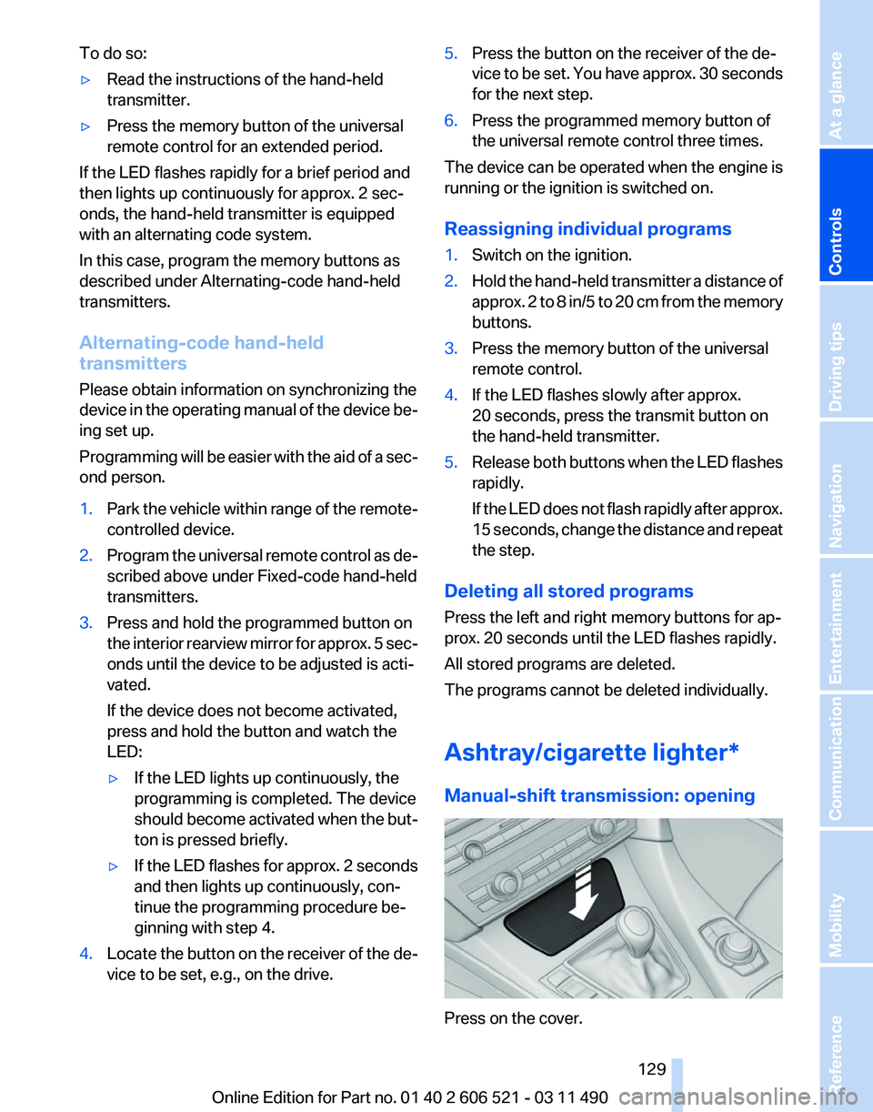
Ashtray/cigarette lighter
*
Manual-shift transmission: opening Press on the cover.
Seite 129
129Online Edition for Part no. 01 40 2 606 521 - 03 11 490
Reference Mobility Communication Entertainment Navigation Driving tips
Controls At a glance
Page 131 of 282
Ski bag*
Capacity
The ski bag makes it possible to transport two
pairs of skis up to a length of 6 ft/2.10 m.
Preparing and loading the ski bag
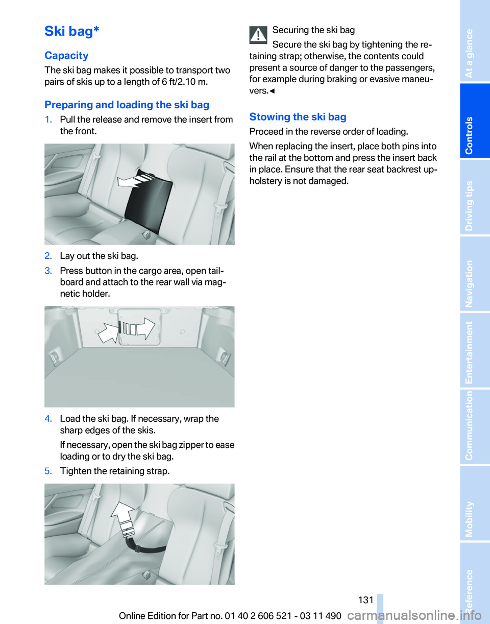
1.
Pull the release and remove the insert from
the front. 2.
Lay out the ski bag.
3. Press button in the cargo area, open tail‐
board and attach to the rear wall via mag‐
netic holder. 4.
Load the ski bag. If necessary, wrap the
sharp edges of the skis.
If
necessary, open the ski bag zipper to ease
loading or to dry the ski bag.
5. Tighten the retaining strap. Securing the ski bag
Secure the ski bag by tightening the re‐
taining strap; otherwise, the contents could
present a source of danger to the passengers,
for example during braking or evasive maneu‐
vers.◀
Stowing the ski bag
Proceed in the reverse order of loading.
When replacing the insert, place both pins into
the rail at the bottom and press the insert back
in place. Ensure that the rear seat backrest up‐
holstery is not damaged. Seite 131
131Online Edition for Part no. 01 40 2 606 521 - 03 11 490
Reference Mobility Communication Entertainment Navigation Driving tips
Controls At a glance
Page 141 of 282
4.
The resulting figure equals the available
amount
of cargo and luggage load capacity.
For example, if the YYY amount equals
1,000 lbs and there will be four 150 lbs pas‐
sengers in your vehicle, the amount of avail‐
able cargo and luggage load capacity is
400 lbs: 1,000 lbs minus 600 lbs = 400 lbs.
5. Determine the combined weight of luggage
and
cargo being loaded on the vehicle. That
weight may not safely exceed the available
cargo and luggage load capacity calculated
in Step 4.
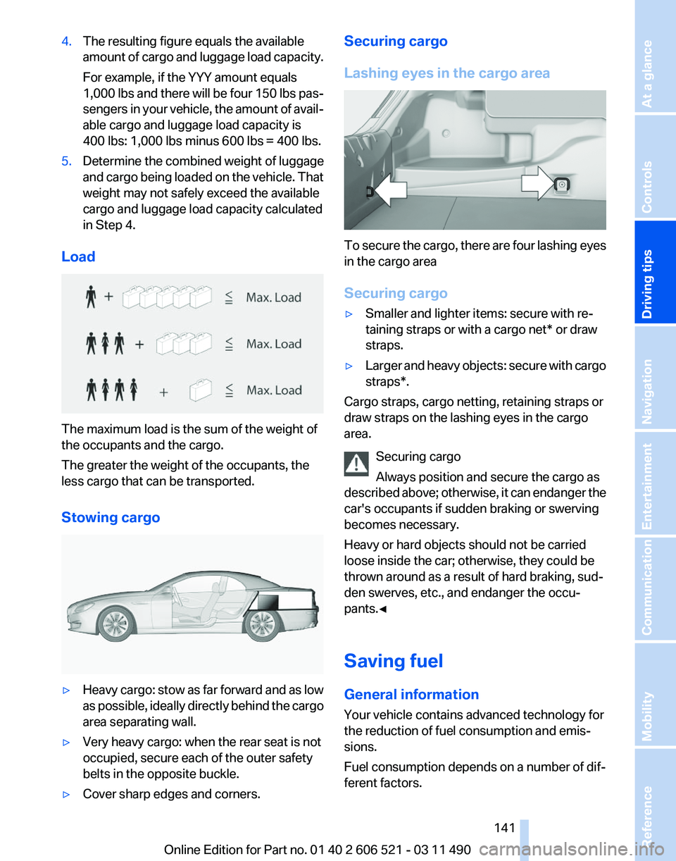
Load The maximum load is the sum of the weight of
the occupants and the cargo.
The greater the weight of the occupants, the
less cargo that can be transported.
Stowing cargo
▷
Heavy cargo: stow as far forward and as low
as
possible, ideally directly behind the cargo
area separating wall.
▷ Very heavy cargo: when the rear seat is not
occupied, secure each of the outer safety
belts in the opposite buckle.
▷ Cover sharp edges and corners. Securing cargo
Lashing eyes in the cargo area
To secure the cargo, there are four lashing eyes
in the cargo area
Securing cargo
▷
Smaller and lighter items: secure with re‐
taining straps or with a
cargo net* or draw
straps.
▷ Larger and heavy objects: secure with cargo
straps*.
Cargo straps, cargo netting, retaining straps or
draw straps on the lashing eyes in the cargo
area.
Securing cargo
Always position and secure the cargo as
described
above; otherwise, it can endanger the
car's occupants if sudden braking or swerving
becomes necessary.
Heavy or hard objects should not be carried
loose inside the car; otherwise, they could be
thrown around as a result of hard braking, sud‐
den swerves, etc., and endanger the occu‐
pants.◀
Saving fuel
General information
Your vehicle contains advanced technology for
the reduction of fuel consumption and emis‐
sions.
Fuel consumption depends on a number of dif‐
ferent factors. Seite 141
141Online Edition for Part no. 01 40 2 606 521 - 03 11 490
Reference Mobility Communication Entertainment Navigation
Driving tips Controls At a glance
Page 235 of 282
Maximum speed with snow chains
Do
not exceed a speed of 30 mph/50 km/h when
using snow chains.
Snow chain detection*
The concept
When using snow chains, you should set
whether you are driving with or without snow
chains via the iDrive.
The snow chain detection system supports you
by automatically showing the detected state on
the Control Display.
When snow chains are in use, the rear axle steer‐
ing of the Integral Active Steering* is deacti‐
vated automatically.
At speeds above the maximum allowable speed
with snow chains of 30 mph/50 km/h, the rear
axle steering is activated again automatically.
Activating the status
1. "Settings"
2. "Tire chains"
3. "Tire chains installed"
Automatic detection
If functioning properly:
▷ Snow chains are mounted. The setting is not
activated .
After you drive a short distance, a Check
Control message is shown and the state is
activated automatically.
Confirm the automatic activation.
▷ Snow chains are not mounted. The setting
is activated .
At speeds above 30 mph/50 km/h, a Check
Control message is displayed. Deactivate
the status manually.
If not functioning properly:
▷ Snow chains are mounted. The setting is not
activated .
A Check Control message is not displayed.
The
automatic detection system is malfunc‐
tioning. Activate the status manually. Activating/deactivating rear axle
steering
If the status indicating that snow chains are in
use
is activated, the rear axle steering is deacti‐
vated automatically.
At speeds above 30 mph/50 km/h, the rear axle
steering is activated again, even though snow
chains are in use.
Seite 235
235Online Edition for Part no. 01 40 2 606 521 - 03 11 490
Reference
Mobility Communication Entertainment Navigation Driving tips Controls At a glance
Page 245 of 282
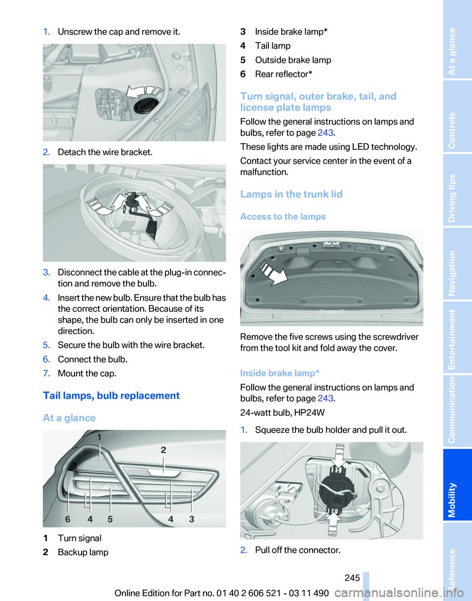
1.
Unscrew the cap and remove it. 2.
Detach the wire bracket. 3.
Disconnect the cable at the plug-in connec‐
tion and remove the bulb.
4. Insert the new bulb. Ensure that the bulb has
the correct orientation. Because of its
shape, the bulb can only be inserted in one
direction.
5. Secure the bulb with the wire bracket.
6. Connect the bulb.
7. Mount the cap.
Tail lamps, bulb replacement
At a glance 1
Turn signal
2 Backup lamp 3
Inside brake lamp*
4 Tail lamp
5 Outside brake lamp
6 Rear reflector*
Turn signal, outer brake, tail, and
license plate lamps
Follow the general instructions on lamps and
bulbs, refer to page 243.
These lights are made using LED technology.
Contact your service center in the event of a
malfunction.
Lamps in the trunk lid
Access to the lamps Remove the five screws using the screwdriver
from the tool kit and fold away the cover.
Inside brake lamp
*
Follow the general instructions on lamps and
bulbs, refer to page 243.
24-watt bulb, HP24W
1. Squeeze the bulb holder and pull it out. 2.
Pull off the connector.
Seite 245
245Online Edition for Part no. 01 40 2 606 521 - 03 11 490
Reference
Mobility Communication Entertainment Navigation Driving tips Controls At a glance
Page 249 of 282
Assist Response Center may still be able to
hear you.
Initiating an Emergency Request
automatically
Under certain conditions, an Emergency Re‐
quest is automatically initiated immediately after
a severe accident. Automatic Collision Notifica‐
tion is not affected by pressing the SOS button.
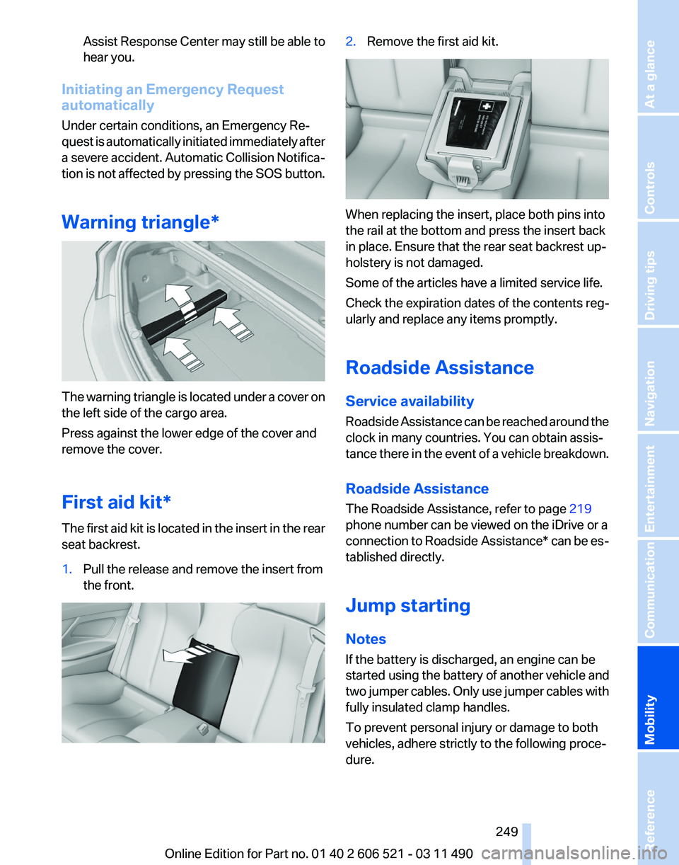
Warning triangle* The warning triangle is located under a cover on
the left side of the cargo area.
Press against the lower edge of the cover and
remove the cover.
First aid kit*
The first aid kit is located in the insert in the rear
seat backrest.
1.
Pull the release and remove the insert from
the front. 2.
Remove the first aid kit. When replacing the insert, place both pins into
the rail at the bottom and press the insert back
in place. Ensure that the rear seat backrest up‐
holstery is not damaged.
Some of the articles have a limited service life.
Check the expiration dates of the contents reg‐
ularly and replace any items promptly.
Roadside Assistance
Service availability
Roadside Assistance can be reached around the
clock in many countries. You can obtain assis‐
tance there in the event of a vehicle breakdown.
Roadside Assistance
The Roadside Assistance, refer to page
219
phone number can be viewed on the iDrive or a
connection to Roadside Assistance* can be es‐
tablished directly.
Jump starting
Notes
If the battery is discharged, an engine can be
started using the battery of another vehicle and
two jumper cables. Only use jumper cables with
fully insulated clamp handles.
To prevent personal injury or damage to both
vehicles, adhere strictly to the following proce‐
dure.
Seite 249
249Online Edition for Part no. 01 40 2 606 521 - 03 11 490
Reference
Mobility Communication Entertainment Navigation Driving tips Controls At a glance