2012 BMW 640I CONVERTIBLE navigation system
[x] Cancel search: navigation systemPage 71 of 282
Windshield washer nozzles
The washer jets are automatically heated*
whenever the ignition is switched on.
Fold-out position of the wipers
Required when changing the wiper blades or
under frosty conditions, for example.
1.
Switch off the ignition.
2. Under frosty conditions, ensure that the
wiper blades are not frozen onto the wind‐
shield.
3. Press the wiper lever up beyond the point of
resistance
and hold it for approx. 3 seconds,
until the wiper remains in a nearly vertical
position.
After the wipers are folded back down, the wiper
system must be reactivated.
Fold the wipers back down
Before switching the ignition on, fold the
wipers
back down to the windshield; otherwise,
the wipers may become damaged when they are
switched on.◀
1. Switch on the ignition.
2. Press the wiper levers down. The wipers
move
to their resting position and are ready
for operation.
Washer fluid
General information Antifreeze for washer fluid
Antifreeze is flammable. Therefore, keep
it away from sources of ignition.
Only
keep it in the closed original container and
inaccessible to children.
Follow the instructions on the container.◀ Washer fluid reservoir
Adding washer fluid
Only add washer fluid when the engine is
cool, and then close the cover completely to
avoid
contact between the washer fluid and hot
engine parts.
Otherwise, there is the danger of fire and a risk
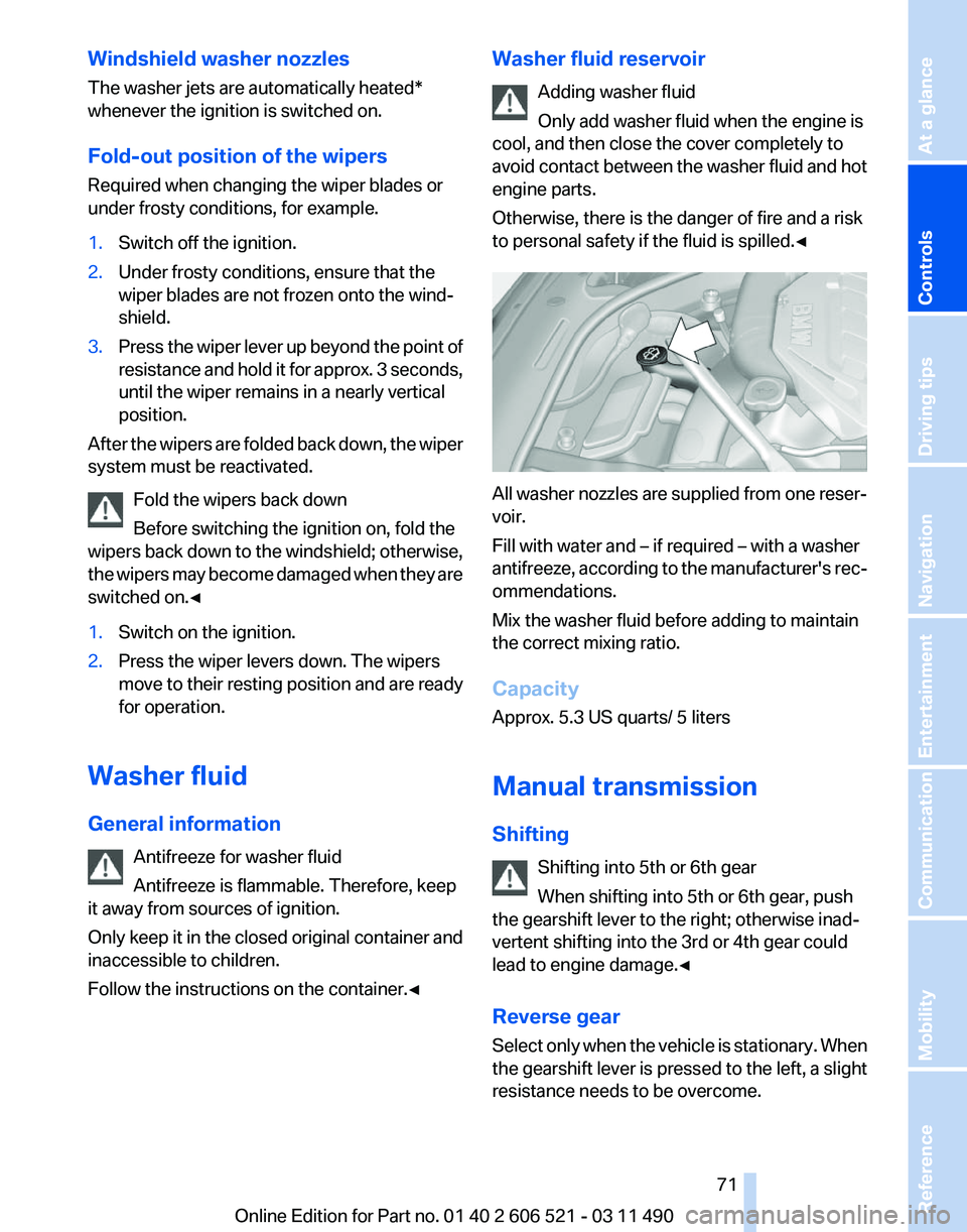
to personal safety if the fluid is spilled.◀ All washer nozzles are supplied from one reser‐
voir.
Fill with water and – if required – with a washer
antifreeze,
according to the manufacturer's rec‐
ommendations.
Mix the washer fluid before adding to maintain
the correct mixing ratio.
Capacity
Approx. 5.3 US quarts/ 5 liters
Manual transmission
Shifting
Shifting into 5th or 6th gear
When shifting into 5th or 6th gear, push
the gearshift lever to the right; otherwise inad‐
vertent shifting into the 3rd or 4th gear could
lead to engine damage.◀
Reverse gear
Select only when the vehicle is stationary. When
the gearshift lever is pressed to the left, a slight
resistance needs to be overcome. Seite 71
71Online Edition for Part no. 01 40 2 606 521 - 03 11 490
Reference Mobility Communication Entertainment Navigation Driving tips
Controls At a glance
Page 73 of 282
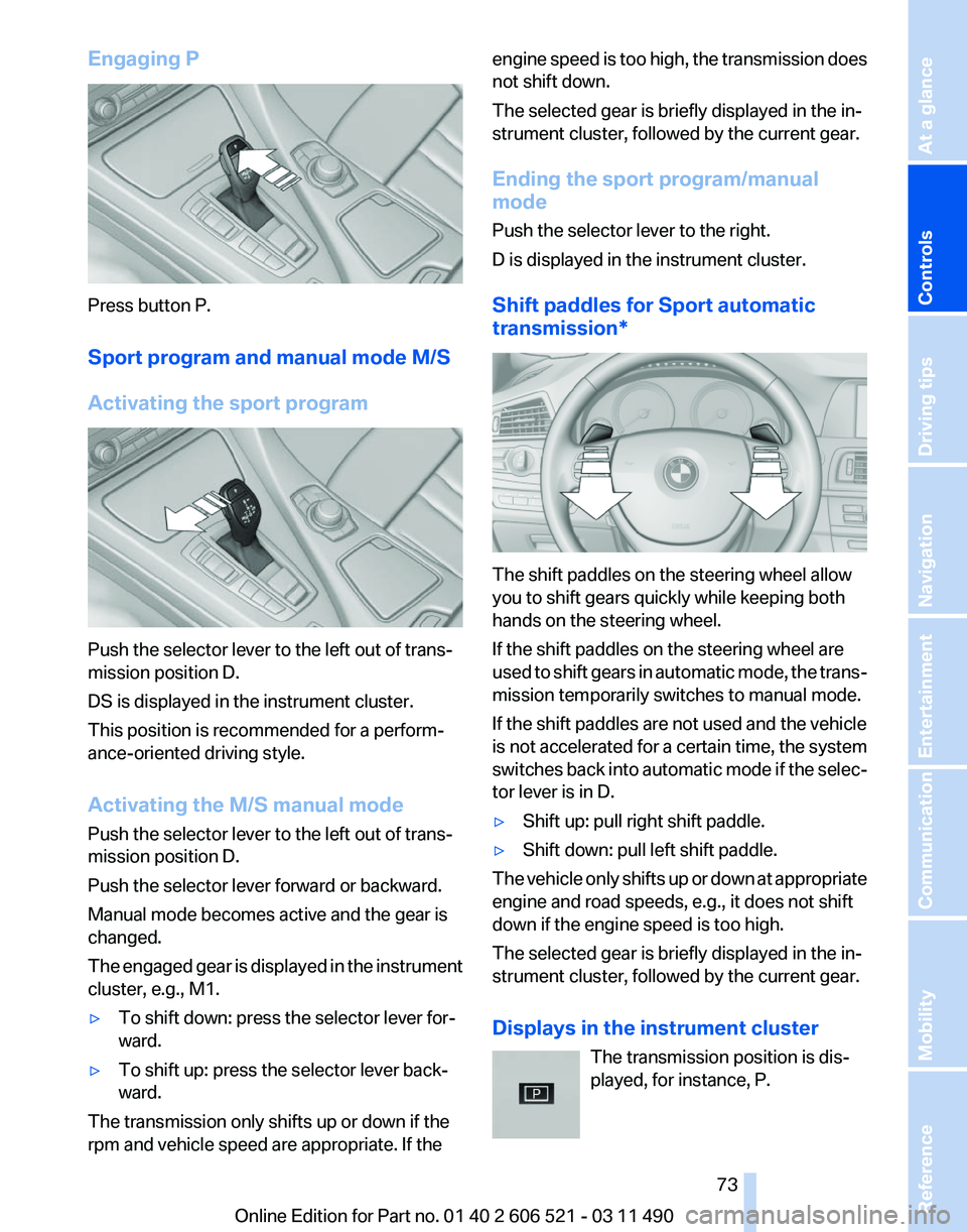
Engaging P
Press button P.
Sport program and manual mode M/S
Activating the sport program
Push the selector lever to the left out of trans‐
mission position D.
DS is displayed in the instrument cluster.
This position is recommended for a perform‐
ance-oriented driving style.
Activating the M/S manual mode
Push the selector lever to the left out of trans‐
mission position D.
Push the selector lever forward or backward.
Manual mode becomes active and the gear is
changed.
The
engaged gear is displayed in the instrument
cluster, e.g., M1.
▷ To shift down: press the selector lever for‐
ward.
▷ To shift up: press the selector lever back‐
ward.
The transmission only shifts up or down if the
rpm and vehicle speed are appropriate. If the engine speed is too high, the transmission does
not shift down.
The selected gear is briefly displayed in the in‐
strument cluster, followed by the current gear.
Ending the sport program/manual
mode
Push the selector lever to the right.
D is displayed in the instrument cluster.
Shift paddles for Sport automatic
transmission*
The shift paddles on the steering wheel allow
you to shift gears quickly while keeping both
hands on the steering wheel.
If the shift paddles on the steering wheel are
used
to shift gears in automatic mode, the trans‐
mission temporarily switches to manual mode.
If the shift paddles are not used and the vehicle
is not accelerated for a certain time, the system
switches back into automatic mode if the selec‐
tor lever is in D.
▷ Shift up: pull right shift paddle.
▷ Shift down: pull left shift paddle.
The vehicle only shifts up or down at appropriate
engine and road speeds, e.g., it does not shift
down if the engine speed is too high.
The selected gear is briefly displayed in the in‐
strument cluster, followed by the current gear.
Displays in the instrument cluster The transmission position is dis‐
played, for instance, P. Seite 73
73Online Edition for Part no. 01 40 2 606 521 - 03 11 490
Reference Mobility Communication Entertainment Navigation Driving tips
Controls At a glance
Page 77 of 282
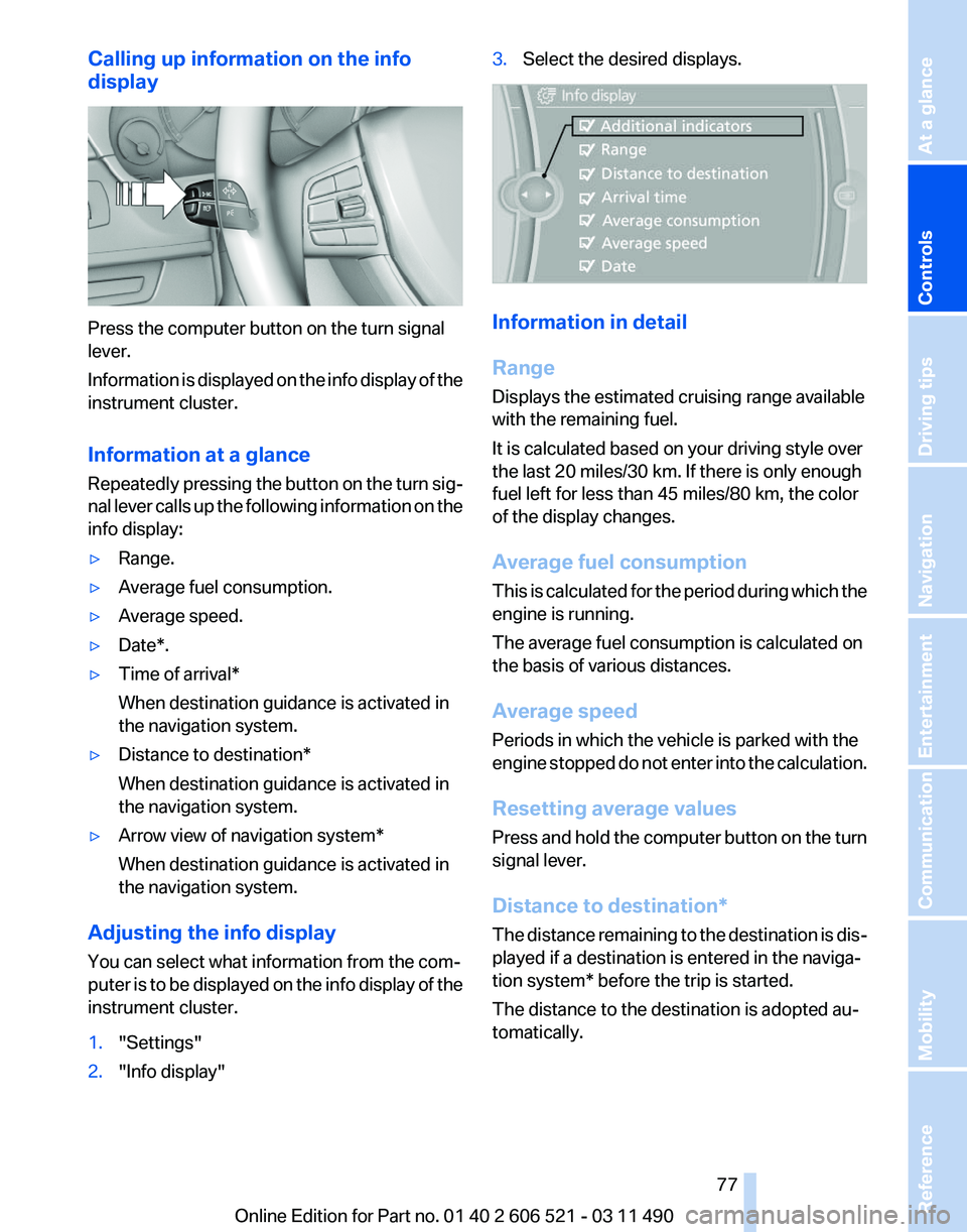
Calling up information on the info
display
Press the computer button on the turn signal
lever.
Information
is displayed on the info display of the
instrument cluster.
Information at a glance
Repeatedly pressing the button on the turn sig‐
nal lever calls up the following information on the
info display:
▷ Range.
▷ Average fuel consumption.
▷ Average speed.
▷ Date*.
▷ Time of arrival*
When destination guidance is activated in
the navigation system.
▷ Distance to destination*
When destination guidance is activated in
the navigation system.
▷ Arrow view of navigation system*
When destination guidance is activated in
the navigation system.
Adjusting the info display
You can select what information from the com‐
puter
is to be displayed on the info display of the
instrument cluster.
1. "Settings"
2. "Info display" 3.
Select the desired displays. Information in detail
Range
Displays the estimated cruising range available
with the remaining fuel.
It is calculated based on your driving style over
the last 20 miles/30 km. If there is only enough
fuel left for less than 45 miles/80 km, the color
of the display changes.
Average fuel consumption
This
is calculated for the period during which the
engine is running.
The average fuel consumption is calculated on
the basis of various distances.
Average speed
Periods in which the vehicle is parked with the
engine stopped do not enter into the calculation.
Resetting average values
Press and hold the computer button on the turn
signal lever.
Distance to destination*
The distance remaining to the destination is dis‐
played if a destination is entered in the naviga‐
tion system* before the trip is started.
The distance to the destination is adopted au‐
tomatically.
Seite 77
77Online Edition for Part no. 01 40 2 606 521 - 03 11 490
Reference Mobility Communication Entertainment Navigation Driving tips
Controls At a glance
Page 78 of 282
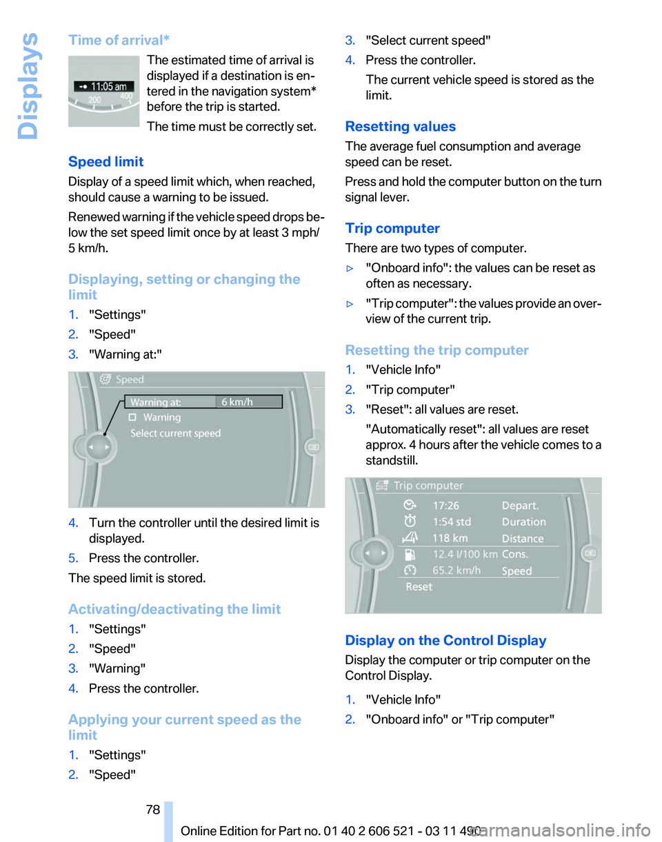
Time of arrival*
The estimated time of arrival is
displayed if a destination is en‐
tered in the navigation system
*
before the trip is started.
The time must be correctly set.
Speed limit
Display of a speed limit which, when reached,
should cause a warning to be issued.
Renewed warning if the vehicle speed drops be‐
low the set speed limit once by at least 3 mph/
5 km/h.
Displaying, setting or changing the
limit
1. "Settings"
2. "Speed"
3. "Warning at:" 4.
Turn the controller until the desired limit is
displayed.
5. Press the controller.
The speed limit is stored.
Activating/deactivating the limit
1. "Settings"
2. "Speed"
3. "Warning"
4. Press the controller.
Applying your current speed as the
limit
1. "Settings"
2. "Speed" 3.
"Select current speed"
4. Press the controller.
The current vehicle speed is stored as the
limit.
Resetting values
The average fuel consumption and average
speed can be reset.
Press
and hold the computer button on the turn
signal lever.
Trip computer
There are two types of computer.
▷ "Onboard info": the values can be reset as
often as necessary.
▷ "Trip
computer": the values provide an over‐
view of the current trip.
Resetting the trip computer
1. "Vehicle Info"
2. "Trip computer"
3. "Reset": all values are reset.
"Automatically reset": all values are reset
approx.
4 hours after the vehicle comes to a
standstill. Display on the Control Display
Display the computer or trip computer on the
Control Display.
1.
"Vehicle Info"
2. "Onboard info" or "Trip computer"
Seite 78
78 Online Edition for Part no. 01 40 2 606 521 - 03 11 490
Displays
Page 79 of 282
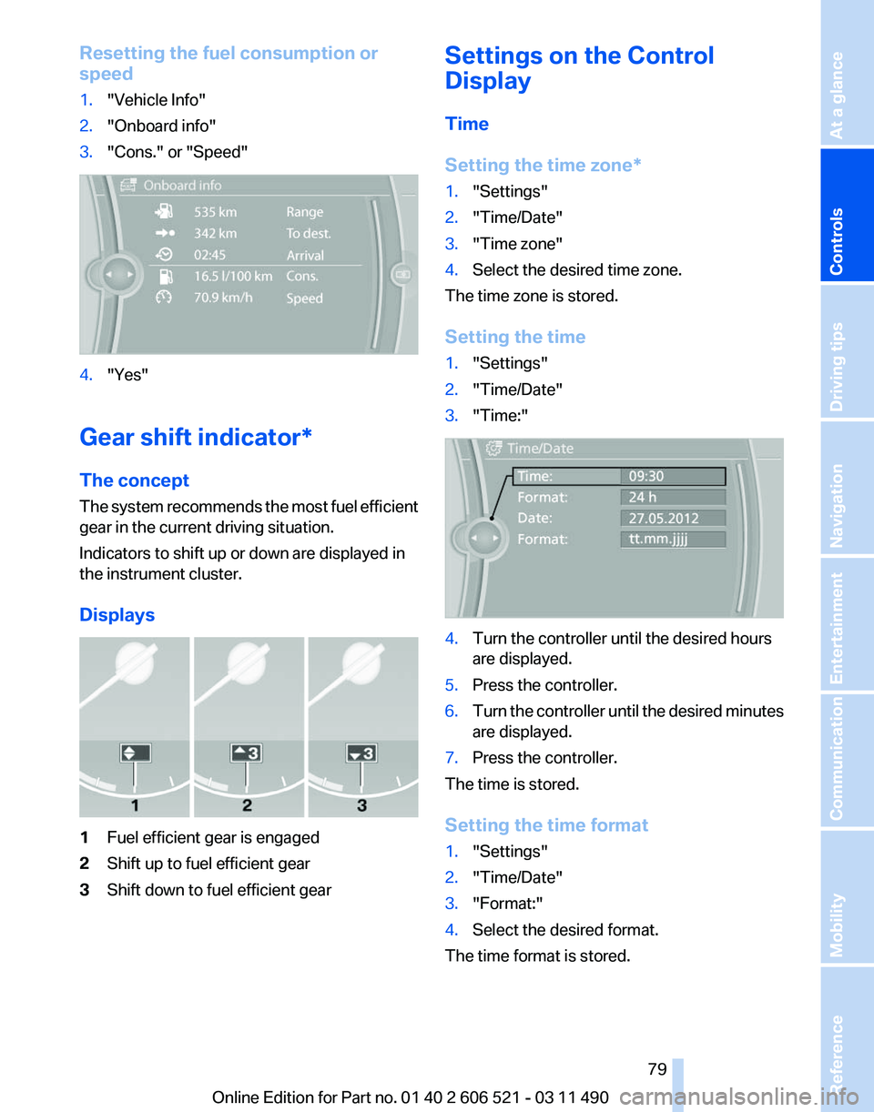
Resetting the fuel consumption or
speed
1.
"Vehicle Info"
2. "Onboard info"
3. "Cons." or "Speed" 4.
"Yes"
Gear shift indicator*
The concept
The
system recommends the most fuel efficient
gear in the current driving situation.
Indicators to shift up or down are displayed in
the instrument cluster.
Displays 1
Fuel efficient gear is engaged
2 Shift up to fuel efficient gear
3 Shift down to fuel efficient gear Settings on the Control
Display
Time
Setting the time zone
*
1. "Settings"
2. "Time/Date"
3. "Time zone"
4. Select the desired time zone.
The time zone is stored.
Setting the time
1. "Settings"
2. "Time/Date"
3. "Time:" 4.
Turn the controller until the desired hours
are displayed.
5. Press the controller.
6. Turn the controller until the desired minutes
are displayed.
7. Press the controller.
The time is stored.
Setting the time format
1. "Settings"
2. "Time/Date"
3. "Format:"
4. Select the desired format.
The time format is stored.
Seite 79
79Online Edition for Part no. 01 40 2 606 521 - 03 11 490
Reference Mobility Communication Entertainment Navigation Driving tips
Controls At a glance
Page 85 of 282

The setting is stored for the remote control cur‐
rently in use.
Automatic headlamp control
Switch
position : the low beams are switched
on and off automatically, e.g., in tunnels, in twi‐
light or if there is precipitation. The indicator
lamp in the instrument cluster lights up.
A blue sky with the sun low on the horizon can
cause the lights to be switched on.
The low beams always stay on when the fog
lamps are switched on.
Personal responsibility
The automatic headlamp control cannot
serve
as a substitute for your personal judgment
in determining when the lamps should be
switched on in response to ambient lighting
conditions.
For example, the sensors are unable to detect
fog or hazy weather. To avoid safety risks, you
should always switch on the lamps manually un‐
der these conditions.◀
Daytime running lights*
With the ignition switched on, the daytime run‐
ning lights light up in position 0, or .
After the ignition is switched off, the parking
lamps light up in position
.
Roadside parking lamps The vehicle can be illuminated on one side.
Switching on
With the ignition switched off, press the lever
either up or down past the resistance point for
approx. 2 seconds. Switching off
Briefly press the lever to the resistance point in
the opposite direction.
Adaptive light control*
The concept
Adaptive light control is a variable headlamp
control system that enables dynamic illumina‐
tion of the road surface.
Depending on the steering angle and other pa‐
rameters, the light from the headlamp follows
the course of the road.
In tight curves, e.g., on mountainous roads or
when turning, an additional, corner-illuminating
lamp is switched on that lights up the inside of
the curve when the vehicle is moving below a
certain speed.
Controls
Activating
Switch position
with the ignition switched
on.
The turning lamps are automatically switched
on depending on the steering angle or the use
of turn signals.
To
avoid blinding oncoming traffic, the adaptive
light control directs light towards the front pas‐
senger side when the vehicle is at a standstill.
When driving in reverse, only the turning lamp is
active.
Self-leveling headlights
The self-leveling headlights feature adapts the
light distribution to the contours of the road.
The light distribution is lowered on hilltops to
avoid blinding oncoming traffic and tilted in de‐
pressions to increase visibility.
Malfunction
A Check Control message is displayed.
Seite 85
85Online Edition for Part no. 01 40 2 606 521 - 03 11 490
Reference Mobility Communication Entertainment Navigation Driving tips
Controls At a glance
Page 89 of 282
▷
Make sure that the front passenger is sitting
correctly, i.e., keeps his or her feet and legs
in the footwell; otherwise, leg injuries can
occur if the front airbag is triggered.
▷ Do not place slip covers, seat cushions or
other objects on the front passenger seat
that are not approved specifically for seats
with integrated side airbags.
▷ Do not hang pieces of clothing, such as jack‐
ets, over the backrests.
▷ Make sure that occupants keep their heads
away from the side airbag; otherwise, inju‐
ries can occur if the airbags are deployed.
▷ Do not remove the airbag restraint system.
▷ Do not remove the steering wheel.
▷ Do not apply adhesive materials to the air‐
bag cover panels, cover them or modify
them in any way.
▷ Never modify either the individual compo‐
nents
or the wiring in the airbag system. This
also applies to steering wheel covers, the
dashboard, and the seats.◀
Even when all instructions are followed closely,
injury from contact with the airbags cannot be
ruled out in certain situations.
The ignition and inflation noise may lead to
short-term
and, in most cases, temporary hear‐
ing impairment in sensitive individuals.
In the case of a malfunction, deactivation
and after triggering of the airbags
Do not touch the individual components imme‐
diately after the system has been triggered; oth‐
erwise, there is the danger of burns.
Only have the airbags checked, repaired or dis‐
mantled and the airbag generator scrapped by
your service center or a workshop that has the
necessary authorization for handling explosives.
Non-professional attempts to service the sys‐
tem could lead to failure in an emergency or un‐
desired triggering of the airbag, either of which
could result in injury.◀
Warnings and information on the airbags are
also found on the sun visors. Functional readiness of the airbag
system
When
the ignition is switch on, the warn‐
ing lamp in the instrument cluster lights
up briefly and thereby indicates the op‐
erational readiness of the entire airbag system
and the belt tensioner.
Airbag system malfunctioning
▷ In radio ready state, the warning lamp does
not come on.
▷ The warning lamp lights up continuously.
When there is a malfunction, have the air‐
bag system checked immediately
When there is a malfunction, have the airbag
system checked immediately; otherwise, there
is
a risk that the system does not function as ex‐
pected in the event of an accident despite cor‐
responding severity of the accident.◀
Automatic deactivation of the front
passenger airbags
The system determines whether the front pas‐
senger seat is occupied by measuring the re‐
sistance of the human body.
The front, knee, and side airbag on the front
passenger side are activated or deactivated ac‐
cordingly.
Leave feet in the footwell
Make sure that the front passenger keeps
his or her feet in the footwell; otherwise, the front
passenger airbags may not function properly.◀
Child restraint fixing system in the front
passenger seat
Before transporting a child on the front passen‐
ger seat, see the safety notes and instructions
under Children on the front passenger seat.◀
Malfunction of the automatic
deactivation system
When transporting older children and adults, the
front passenger airbags may be deactivated in
certain sitting positions. In this case, the indica‐ Seite 89
89Online Edition for Part no. 01 40 2 606 521 - 03 11 490
Reference Mobility Communication Entertainment Navigation Driving tips
Controls At a glance
Page 91 of 282
Rollover protection system
The concept
The
rollover protection system is activated dur‐
ing an accident or a critical driving situation,
when there is extreme tilt with respect to the
longitudinal axis or when there is loss of ground
contact. The safety frames located behind the
rear headrests extend within fractions of a sec‐
ond.
In addition to the rollover bracket integrated in
the front windshield frame, the rollover protec‐
tion system guarantees the required head clear‐
ance of all vehicle occupants.
Maintaining movement space
Always keep the movement space of the
rollover protection system clear. Otherwise,
there may be damage or injuries when the roll‐
over protection system is triggered.◀
In less severe accidents, the secured safety belt
and, depending on the severity of the accident,
the belt tensioner and airbag restraint system
provide protection.
Triggered rollover protection system
After deployment or damage
After deployment of the rollover protec‐
tion system or in the event of damage, have the
system checked and replaced.
Have this work performed only by your service
center; otherwise, it cannot be ensured that this
safety feature will function properly.◀
Do not move convertible top
When the rollover protection system is ex‐
tended, do not move the convertible top. Oth‐
erwise, damages or injuries may result.◀
If the rollover protection system was not placed
under any stress after an automatic triggering, it
can be pushed back by hand, e.g. to close the
convertible top. Three people are necessary for
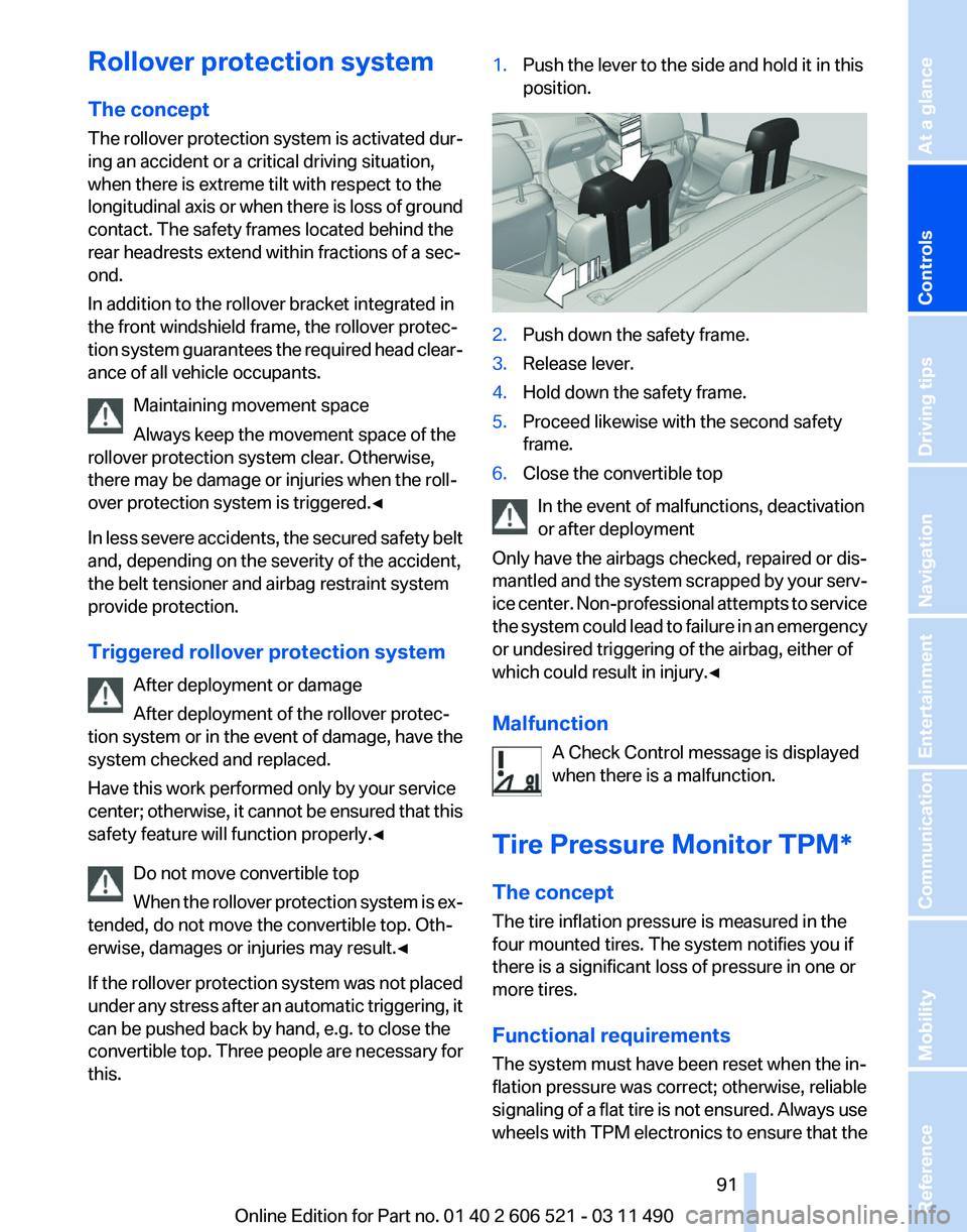
this. 1.
Push the lever to the side and hold it in this
position. 2.
Push down the safety frame.
3. Release lever.
4. Hold down the safety frame.
5. Proceed likewise with the second safety
frame.
6. Close the convertible top
In the event of malfunctions, deactivation
or after deployment
Only have the airbags checked, repaired or dis‐
mantled
and the system scrapped by your serv‐
ice center. Non-professional attempts to service
the system could lead to failure in an emergency
or undesired triggering of the airbag, either of
which could result in injury.◀
Malfunction
A Check Control message is displayed
when there is a malfunction.
Tire Pressure Monitor TPM*
The concept
The tire inflation pressure is measured in the
four mounted tires. The system notifies you if
there is a significant loss of pressure in one or
more tires.
Functional requirements
The system must have been reset when the in‐
flation pressure was correct; otherwise, reliable
signaling of a flat tire is not ensured. Always use
wheels with TPM electronics to ensure that the Seite 91
91Online Edition for Part no. 01 40 2 606 521 - 03 11 490
Reference Mobility Communication Entertainment Navigation Driving tips
Controls At a glance