2012 BMW 640I CONVERTIBLE tow
[x] Cancel search: towPage 97 of 282
Lane departure warning*
The concept
This system issues a warning at speeds above
approx. 40 mph/65 km/h if the vehicle is about
to leave the lane on roads with lane markings.
The steering wheel begins vibrating gently.
The system does not provide a warning if the
turn signal is set before leaving the lane.
Switching on/off
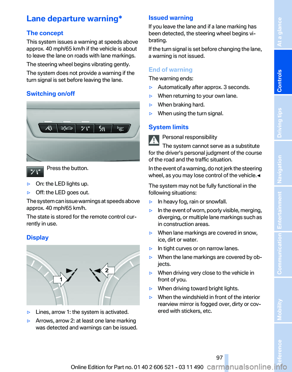
Press the button.
▷ On: the LED lights up.
▷ Off: the LED goes out.
The system can issue warnings at speeds above
approx. 40 mph/65 km/h.
The state is stored for the remote control cur‐
rently in use.
Display ▷
Lines, arrow 1: the system is activated.
▷ Arrows, arrow 2: at least one lane marking
was detected and warnings can be issued. Issued warning
If you leave the lane and if a lane marking has
been detected, the steering wheel begins vi‐
brating.
If
the turn signal is set before changing the lane,
a warning is not issued.
End of warning
The warning ends:
▷ Automatically after approx. 3 seconds.
▷ When returning to your own lane.
▷ When braking hard.
▷ When using the turn signal.
System limits Personal responsibility
The system cannot serve as a substitute
for
the driver's personal judgment of the course
of the road and the traffic situation.
In the event of a warning, do not jerk the steering
wheel, as you may lose control of the vehicle.◀
The system may not be fully functional in the
following situations:
▷ In heavy fog, rain or snowfall.
▷ In the event of worn, poorly visible, merging,
diverging,
or multiple lane markings such as
in construction areas.
▷ When lane markings are covered in snow,
ice, dirt or water.
▷ In tight curves or on narrow lanes.
▷ When the lane markings are covered by ob‐
jects.
▷ When driving very close to the vehicle in
front of you.
▷ When driving toward bright lights.
▷ When the windshield in front of the interior
rearview mirror is fogged over, dirty or cov‐
ered with stickers, etc. Seite 97
97Online Edition for Part no. 01 40 2 606 521 - 03 11 490
Reference Mobility Communication Entertainment Navigation Driving tips
Controls At a glance
Page 108 of 282
Measurement
Measurements
are made by ultrasound sensors
in the bumpers.
The range is approx. 6 ft/2 m.
An acoustic warning is first given:
▷ By the front* sensors and the two rear cor‐
ner sensors at approx. 24 in/60 cm.
▷ By the rear middle sensors at approx. 5 ft/
1.50 m.
System limits Check the traffic situation as well
PDC cannot serve as a substitute for the
driver's personal judgment of the traffic situa‐
tion.
Check the traffic situation around the vehi‐
cle with your own eyes. Otherwise, an accident
could result from road users or objects located
outside of the PDC detection range.
Loud noises from outside and inside the vehicle
may prevent you from hearing the PDC's signal
tone.◀
Avoid driving quickly with PDC
Avoid approaching an object quickly.
Avoid driving away quickly while PDC is not yet
active.
For technical reasons, the system may other‐
wise be too late in issuing a warning.◀
Limits of ultrasonic measurement
The detection of objects can reach the physical
limits of ultrasonic measurement, for instance:
▷ With tow bars and trailer hitches.
▷ With thin or wedge-shaped objects.
▷ With low objects.
▷ With objects with corners and sharp edges.
Low objects already displayed, e.g., curbs, can
move
into the blind area of the sensors before or
after a continuous tone sounds.
High, protruding objects such as ledges may not
be detected. False warnings
PDC may issue a warning under the following
conditions even though there is no obstacle
within the detection range:
▷
In heavy rain.
▷ When sensors are very dirty or covered in
ice.
▷ When sensors are covered in snow.
▷ On rough road surfaces.
▷ In large buildings with right angles and
smooth
walls, e.g., in underground garages.
▷ In heavy exhaust.
▷ Due to other ultrasound sources, e.g.,
sweeping machines, high pressure steam
cleaners or neon lights.
Switching on automatically
Select transmission position R with the engine
running.
Switching off automatically
The
system switches off and the LED goes out:
▷ After approx. 160 ft/50 m when driving for‐
ward.
▷ Above approx. 22 mph/36 km/h when driv‐
ing forward.
Switch on the system again if necessary.
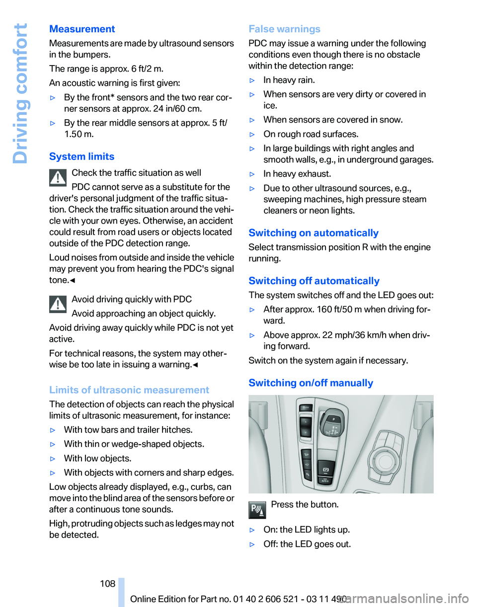
Switching on/off manually Press the button.
▷ On: the LED lights up.
▷ Off: the LED goes out. Seite 108
108 Online Edition for Part no. 01 40 2 606 521 - 03 11 490
Driving comfort
Page 118 of 282

Limits of ultrasonic measurement
The
detection of objects can reach the physical
limits of ultrasonic measurement, for instance:
▷ With tow bars and trailer hitches.
▷ With thin or wedge-shaped objects.
▷ With elevated, protruding objects such as
ledges or cargo.
▷ With objects with corners and sharp edges.
▷ With objects with a fine surface structure,
such as fences.
The parking assistant may identify parking
spaces that are not suitable for parking.
Ultrasound sensors The ultrasounds sensors used to measure park‐
ing spaces are located in the side turn signals.
To ensure full operability:
▷
Keep the sensors clean and free of ice.
▷ When using a pressure washer, keep the
sprayer moving and maintain a distance of
at least 12 in/30 cm from the sensors.
Night Vision with pedestrian
detection*
The concept
Night
Vision with pedestrian detection is a night
vision system.
An infrared camera records the area in front of
the vehicle and displays the image on the Con‐
trol Display.
The picture is a heat image. The system has an
integrated pedestrian detection function that
detects pedestrians and cyclists. Warm objects that are similar in shape to human beings are
detected by the system.
Personal responsibility
Night Vision cannot replace the driver's
personal judgment of the visibility conditions
and
the traffic situation. The view ahead and the
actual visibility conditions must always be the
basis on which the vehicle speed is adjusted;
otherwise, there is a risk to road safety.◀
Heat image The image shows the heat radiated by objects
in the field of view of the camera.
Warm objects have a light appearance and cold
objects, a dark appearance.
The ability to detect an object depends on the
temperature
difference between the object and
the background and on the level of heat radiation
emitted by the object. Objects that are similar in
temperature to the environment or that radiate
very little heat are difficult to detect.
For safety reasons, when driving at speeds
above approx. 3 mph/5 km/h and in low ambient
light, the image is only displayed when the low
beams are switched on.
A still image is displayed at regular intervals for
a fraction of a second. Seite 118
118 Online Edition for Part no. 01 40 2 606 521 - 03 11 490
Driving comfort
Page 126 of 282
Switching the system on/off
Switching off
▷
Complete system:
At the lowest fan speed, press the
left
side of the button on the driver's
side. ▷
On the front passenger side:
At the lowest fan speed, press the
left side of the button on the front
passenger side. Switching on
Press any button.
Microfilter/activated-charcoal filter
The microfilter removes dust and pollen from
the incoming air.
The activated-charcoal filter removes gaseous
pollutants from the outside air that enters the
vehicle.
This combined filter should be replaced during
scheduled
maintenance of your vehicle., refer to
page 241
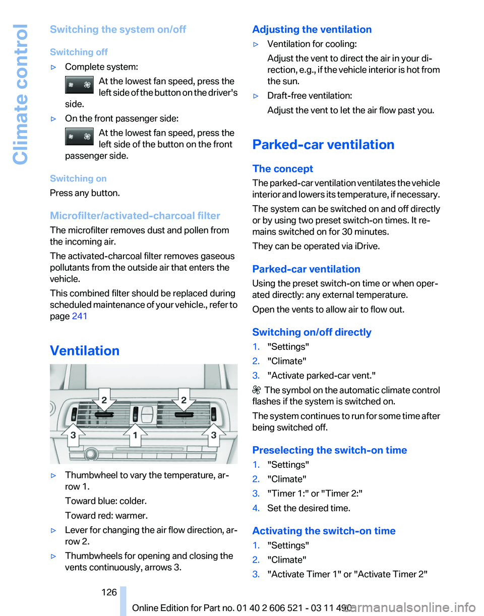
Ventilation ▷
Thumbwheel to vary the temperature, ar‐
row 1.
Toward blue: colder.
Toward red: warmer.
▷ Lever for changing the air flow direction, ar‐
row 2.
▷ Thumbwheels for opening and closing the
vents continuously, arrows 3. Adjusting the ventilation
▷
Ventilation for cooling:
Adjust the vent to direct the air in your di‐
rection,
e.g., if the vehicle interior is hot from
the sun.
▷ Draft-free ventilation:
Adjust the vent to let the air flow past you.
Parked-car ventilation
The concept
The
parked-car ventilation ventilates the vehicle
interior and lowers its temperature, if necessary.
The system can be switched on and off directly
or by using two preset switch-on times. It re‐
mains switched on for 30 minutes.
They can be operated via iDrive.
Parked-car ventilation
Using the preset switch-on time or when oper‐
ated directly: any external temperature.
Open the vents to allow air to flow out.
Switching on/off directly
1. "Settings"
2. "Climate"
3. "Activate parked-car vent." The symbol on the automatic climate control
flashes if the system is switched on.
The
system continues to run for some time after
being switched off.
Preselecting the switch-on time
1. "Settings"
2. "Climate"
3. "Timer 1:" or "Timer 2:"
4. Set the desired time.
Activating the switch-on time
1. "Settings"
2. "Climate"
3. "Activate Timer 1" or "Activate Timer 2"
Seite 126
126 Online Edition for Part no. 01 40 2 606 521 - 03 11 490
Climate control
Page 131 of 282
Ski bag*
Capacity
The ski bag makes it possible to transport two
pairs of skis up to a length of 6 ft/2.10 m.
Preparing and loading the ski bag
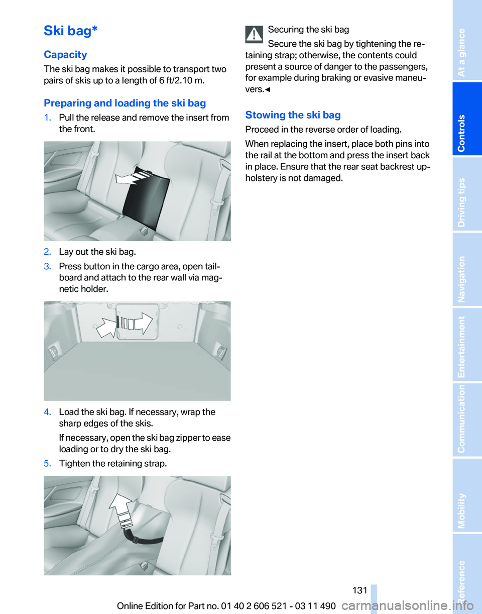
1.
Pull the release and remove the insert from
the front. 2.
Lay out the ski bag.
3. Press button in the cargo area, open tail‐
board and attach to the rear wall via mag‐
netic holder. 4.
Load the ski bag. If necessary, wrap the
sharp edges of the skis.
If
necessary, open the ski bag zipper to ease
loading or to dry the ski bag.
5. Tighten the retaining strap. Securing the ski bag
Secure the ski bag by tightening the re‐
taining strap; otherwise, the contents could
present a source of danger to the passengers,
for example during braking or evasive maneu‐
vers.◀
Stowing the ski bag
Proceed in the reverse order of loading.
When replacing the insert, place both pins into
the rail at the bottom and press the insert back
in place. Ensure that the rear seat backrest up‐
holstery is not damaged. Seite 131
131Online Edition for Part no. 01 40 2 606 521 - 03 11 490
Reference Mobility Communication Entertainment Navigation Driving tips
Controls At a glance
Page 134 of 282
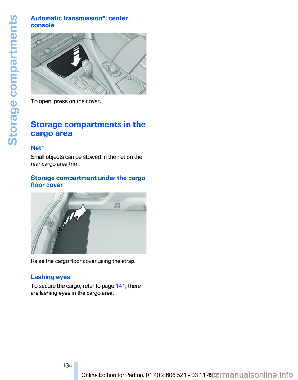
Automatic transmission*: center
console
To open: press on the cover.
Storage compartments in the
cargo area
Net*
Small objects can be stowed in the net on the
rear cargo area trim.
Storage compartment under the cargo
floor cover
Raise the cargo floor cover using the strap.
Lashing eyes
To secure the cargo, refer to page
141, there
are lashing eyes in the cargo area.
Seite 134
134 Online Edition for Part no. 01 40 2 606 521 - 03 11 490Storage compartments
Page 141 of 282
4.
The resulting figure equals the available
amount
of cargo and luggage load capacity.
For example, if the YYY amount equals
1,000 lbs and there will be four 150 lbs pas‐
sengers in your vehicle, the amount of avail‐
able cargo and luggage load capacity is
400 lbs: 1,000 lbs minus 600 lbs = 400 lbs.
5. Determine the combined weight of luggage
and
cargo being loaded on the vehicle. That
weight may not safely exceed the available
cargo and luggage load capacity calculated
in Step 4.
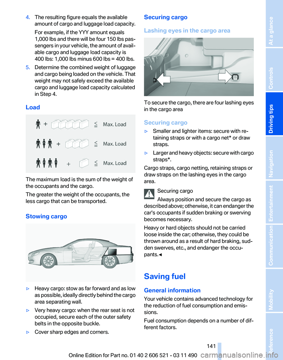
Load The maximum load is the sum of the weight of
the occupants and the cargo.
The greater the weight of the occupants, the
less cargo that can be transported.
Stowing cargo
▷
Heavy cargo: stow as far forward and as low
as
possible, ideally directly behind the cargo
area separating wall.
▷ Very heavy cargo: when the rear seat is not
occupied, secure each of the outer safety
belts in the opposite buckle.
▷ Cover sharp edges and corners. Securing cargo
Lashing eyes in the cargo area
To secure the cargo, there are four lashing eyes
in the cargo area
Securing cargo
▷
Smaller and lighter items: secure with re‐
taining straps or with a
cargo net* or draw
straps.
▷ Larger and heavy objects: secure with cargo
straps*.
Cargo straps, cargo netting, retaining straps or
draw straps on the lashing eyes in the cargo
area.
Securing cargo
Always position and secure the cargo as
described
above; otherwise, it can endanger the
car's occupants if sudden braking or swerving
becomes necessary.
Heavy or hard objects should not be carried
loose inside the car; otherwise, they could be
thrown around as a result of hard braking, sud‐
den swerves, etc., and endanger the occu‐
pants.◀
Saving fuel
General information
Your vehicle contains advanced technology for
the reduction of fuel consumption and emis‐
sions.
Fuel consumption depends on a number of dif‐
ferent factors. Seite 141
141Online Edition for Part no. 01 40 2 606 521 - 03 11 490
Reference Mobility Communication Entertainment Navigation
Driving tips Controls At a glance
Page 146 of 282
Navigation*
Navigation system
General information
The navigation system can determine the pre‐
cise position of the vehicle, with the aid of sat‐
ellites and vehicle sensors, and can reliably
guide you to every entered destination.
Navigation
data are stored in the vehicle and can
be updated.
Entries in stationary vehicle
Enter data only when the vehicle is sta‐
tionary, and always give priority to the applicable
traffic regulations in the event of any contradic‐
tion between traffic and road conditions and the
instructions issued by the navigation system.
Failure to take to this precaution can place you
in violation of the law and put vehicle occupants
and other road users in danger.◀
Destination input
Manual destination entry
General information
The system supports you in entering street
names and house numbers by automatically
completing the entry and providing entry com‐
parisons, refer to page 24.
Stored town/city and street names can be called
up quickly.
▷ If the existing entries should not be changed,
the entries for the state/province and town/
city can be skipped.
▷ Destination guidance is started to the town/
city center if no street is entered.
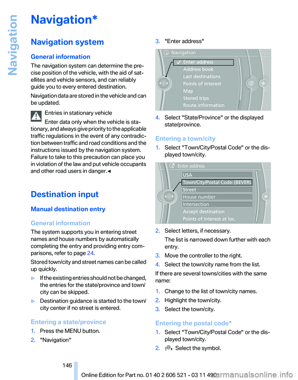
Entering a state/province
1. Press the MENU button.
2. "Navigation" 3.
"Enter address" 4.
Select "State/Province" or the displayed
state/province.
Entering a town/city
1. Select "Town/City/Postal Code" or the dis‐
played town/city. 2.
Select letters, if necessary.
The list is narrowed down further with each
entry.
3. Move the controller to the right.
4. Select the town/city name from the list.
If there are several towns/cities with the same
name:
1. Change to the list of town/city names.
2. Highlight the town/city.
3. Select the town/city.
Entering the postal code*
1. Select "Town/City/Postal Code" or the dis‐
played town/city.
2. Select the symbol.
Seite 146
146 Online Edition for Part no. 01 40 2 606 521 - 03 11 490
Navigation