2012 BMW 6 SERIES warning
[x] Cancel search: warningPage 70 of 303

Electronic displays1Messages, e.g. Check Control 70
Time 73
Date 732Range 733Computer 764Navigation display 158
Service requirements 74Miles/trip miles 735Selection list, for instance radio 75
Current fuel consumption 74
Energy recovery 74
External temperature 736Transmission display 68Check Control
The concept
The Check Control system monitors functions
in the vehicle and notifies you of malfunctions in
the monitored systems.
A Check Control message is displayed as a
combination of indicator or warning lamps and
text messages in the instrument cluster and in
the Head-up Display.
In addition, an acoustic signal may be output and
a text message may appear on the Control Dis‐
play.Indicator/warning lamps
The indicator and warning lamps can light up in
a variety of combinations and colors.
Seite 70ControlsDisplays70
Online Edition for Part no. 01 40 2 607 971 - 09 11 490
Page 71 of 303

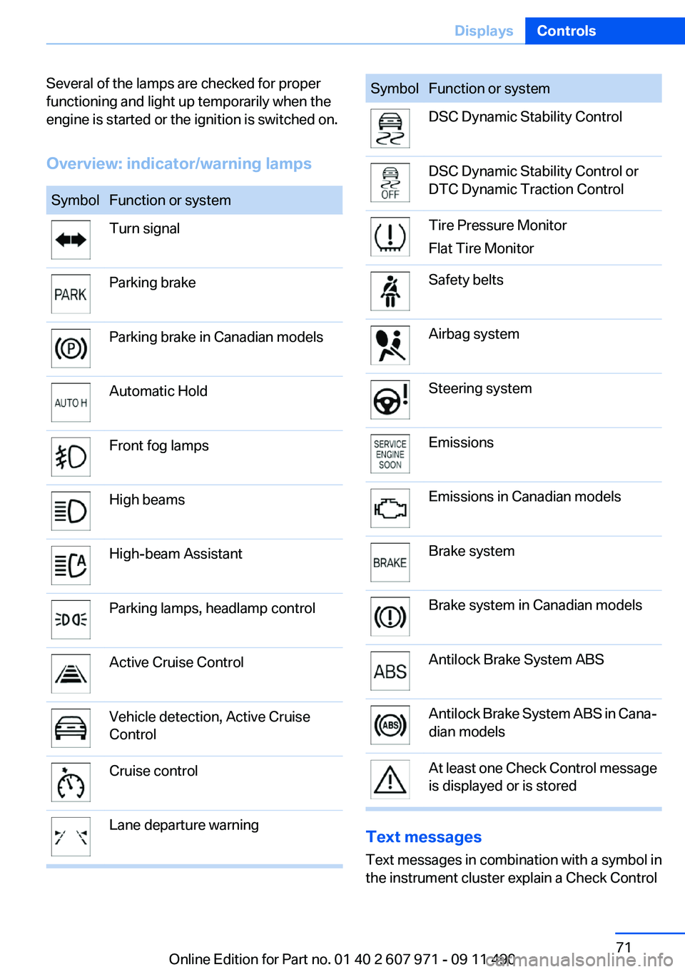
Several of the lamps are checked for proper
functioning and light up temporarily when the
engine is started or the ignition is switched on.
Overview: indicator/warning lampsSymbolFunction or systemTurn signalParking brakeParking brake in Canadian modelsAutomatic HoldFront fog lampsHigh beamsHigh-beam AssistantParking lamps, headlamp controlActive Cruise ControlVehicle detection, Active Cruise
ControlCruise controlLane departure warningSymbolFunction or systemDSC Dynamic Stability ControlDSC Dynamic Stability Control or
DTC Dynamic Traction ControlTire Pressure Monitor
Flat Tire MonitorSafety beltsAirbag systemSteering systemEmissionsEmissions in Canadian modelsBrake systemBrake system in Canadian modelsAntilock Brake System ABSAntilock Brake System ABS in Cana‐
dian modelsAt least one Check Control message
is displayed or is stored
Text messages
Text messages in combination with a symbol in
the instrument cluster explain a Check Control
Seite 71DisplaysControls71
Online Edition for Part no. 01 40 2 607 971 - 09 11 490
Page 72 of 303

message and the meaning of the indicator and
warning lamps.
Supplementary text messages
Addition information, such as on the cause of a
fault or the required action, can be called up via
Check Control.
The supplementary text of urgent messages is
displayed on the Control Display automatically.
Symbols
Depending on the Check Control message, the
following functions can be selected.▷ "Owner's Manual"
Display additional information about the
Check Control message in the integrated
owner's manual.▷ "Service request"
Contact the service partner.▷ "Roadside Assistance"
Contact Roadside Assistance.
Hiding Check Control messages
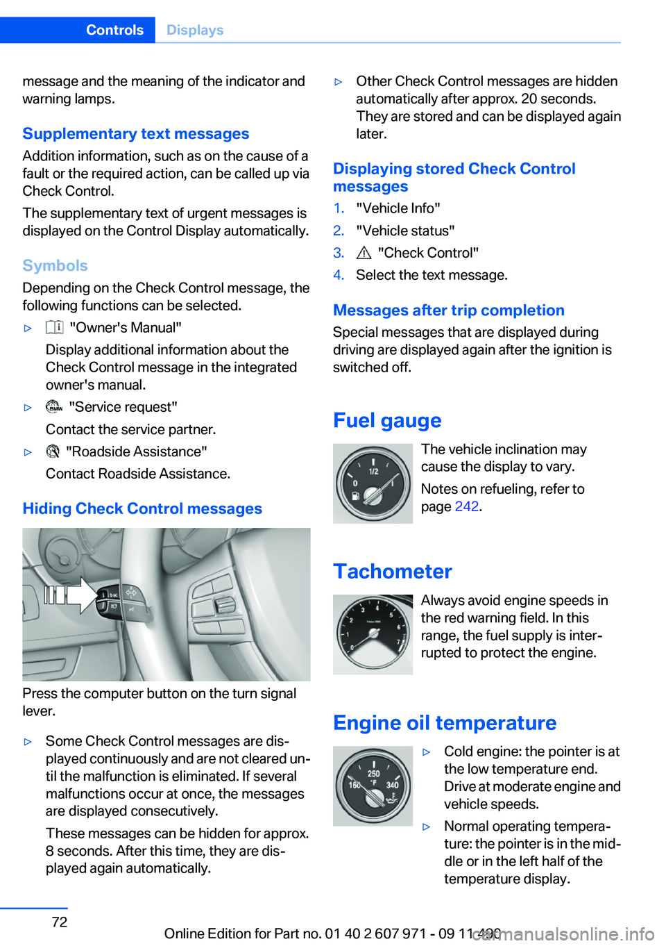
Press the computer button on the turn signal
lever.
▷Some Check Control messages are dis‐
played continuously and are not cleared un‐
til the malfunction is eliminated. If several
malfunctions occur at once, the messages
are displayed consecutively.
These messages can be hidden for approx.
8 seconds. After this time, they are dis‐
played again automatically.▷Other Check Control messages are hidden
automatically after approx. 20 seconds.
They are stored and can be displayed again
later.
Displaying stored Check Control
messages
1."Vehicle Info"2."Vehicle status"3. "Check Control"4.Select the text message.
Messages after trip completion
Special messages that are displayed during
driving are displayed again after the ignition is
switched off.
Fuel gauge The vehicle inclination may
cause the display to vary.
Notes on refueling, refer to
page 242.
Tachometer Always avoid engine speeds in
the red warning field. In this
range, the fuel supply is inter‐
rupted to protect the engine.
Engine oil temperature
▷Cold engine: the pointer is at
the low temperature end.
Drive at moderate engine and
vehicle speeds.▷Normal operating tempera‐
ture: the pointer is in the mid‐
dle or in the left half of the
temperature display.Seite 72ControlsDisplays72
Online Edition for Part no. 01 40 2 607 971 - 09 11 490
Page 73 of 303

▷Hot engine: the pointer is at the high tem‐
perature end. A Check Control message is
displayed in addition.
Coolant temperature
Should the coolant, and with it the engine, be‐
come too hot, a Check Control message is dis‐
played.
Check the coolant level, refer to page 259.
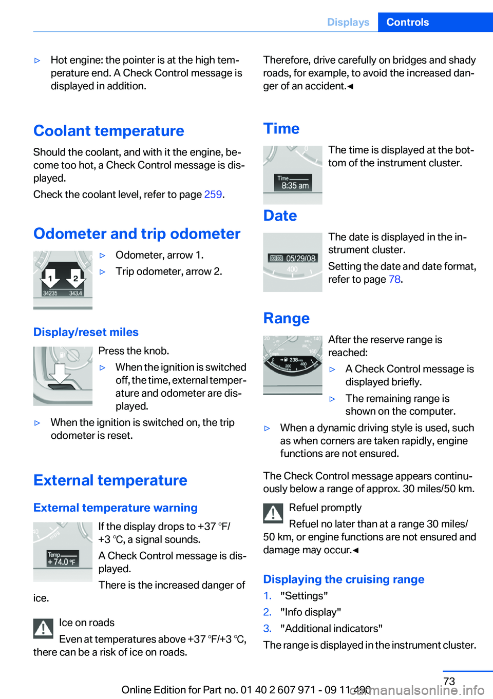
Odometer and trip odometer
▷Odometer, arrow 1.▷Trip odometer, arrow 2.
Display/reset miles Press the knob.
▷When the ignition is switched
off, the time, external temper‐
ature and odometer are dis‐
played.▷When the ignition is switched on, the trip
odometer is reset.
External temperature
External temperature warning If the display drops to +37 ℉/
+3 ℃, a signal sounds.
A Check Control message is dis‐
played.
There is the increased danger of
ice.
Ice on roads
Even at temperatures above +37 ℉/+3 ℃,
there can be a risk of ice on roads.
Therefore, drive carefully on bridges and shady
roads, for example, to avoid the increased dan‐
ger of an accident.◀
Time The time is displayed at the bot‐
tom of the instrument cluster.
Date The date is displayed in the in‐
strument cluster.
Setting the date and date format,
refer to page 78.
Range After the reserve range is
reached:▷A Check Control message is
displayed briefly.▷The remaining range is
shown on the computer.▷When a dynamic driving style is used, such
as when corners are taken rapidly, engine
functions are not ensured.
The Check Control message appears continu‐
ously below a range of approx. 30 miles/50 km.
Refuel promptly
Refuel no later than at a range 30 miles/
50 km, or engine functions are not ensured and
damage may occur.◀
Displaying the cruising range
1."Settings"2."Info display"3."Additional indicators"
The range is displayed in the instrument cluster.
Seite 73DisplaysControls73
Online Edition for Part no. 01 40 2 607 971 - 09 11 490
Page 77 of 303

Time of arrivalThe estimated time of arrival is
displayed if a destination is en‐
tered in the navigation system
before the trip is started.
The time must be correctly set.
Speed limit
Display of a speed limit which, when reached,
should cause a warning to be issued.
Renewed warning if the vehicle speed drops be‐
low the set speed limit once by at least 3 mph/
5 km/h.
Displaying, setting or changing the
limit1."Settings"2."Speed"3."Warning at:"4.Turn the controller until the desired limit is
displayed.5.Press the controller.
The speed limit is stored.
Activating/deactivating the limit
1."Settings"2."Speed"3."Warning"4.Press the controller.Applying your current speed as the
limit1."Settings"2."Speed"3."Select current speed"4.Press the controller.
The current vehicle speed is stored as the
limit.
Trip computer
There are two types of computer.
▷"Onboard info": the values can be reset as
often as necessary.▷" Trip computer": the values provide an over‐
view of the current trip.
Resetting the trip computer
1."Vehicle Info"2."Trip computer"3."Reset": all values are reset.
"Automatically reset": all values are reset
approx. 4 hours after the vehicle comes to a
standstill.
Display on the Control Display
Display the computer or trip computer on the
Control Display.
1."Vehicle Info"2."Onboard info" or "Trip computer"Seite 77DisplaysControls77
Online Edition for Part no. 01 40 2 607 971 - 09 11 490
Page 87 of 303

Protective action
Airbags are not triggered in every impact situa‐
tion, e.g., in less severe accidents or rear-end
collisions.
Information on how to ensure the optimal
protective effect of the airbags▷Keep at a distance from the airbags.▷Always grasp the steering wheel on the
steering wheel rim, holding your hands at
the 3 o'clock and 9 o'clock positions, to keep
the danger of injury to your hands or arms as
low as possible if the airbag is triggered.▷There should be no people, animals, or ob‐
jects between an airbag and a person.▷Do not use the cover of the front airbag on
the front passenger side as a storage area.▷Keep the dashboard and window on the
front passenger side clear, i.e., do not cover
with adhesive labels or coverings, and do not
attach holders such as for navigation instru‐
ments and mobile phones.▷Make sure that the front passenger is sitting
correctly, i.e., keeps his or her feet and legs
in the footwell; otherwise, leg injuries can
occur if the front airbag is triggered.▷Do not place slip covers, seat cushions or
other objects on the front passenger seat
that are not approved specifically for seats
with integrated side airbags.▷Do not hang pieces of clothing, such as jack‐
ets, over the backrests.▷Make sure that occupants keep their heads
away from the side airbag and do not rest
against the head airbag; otherwise, injuries
can occur if the airbags are triggered.▷Do not remove the airbag restraint system.▷Do not remove the steering wheel.▷Do not apply adhesive materials to the air‐
bag cover panels, cover them or modify
them in any way.▷Never modify either the individual compo‐
nents or the wiring in the airbag system. This
also applies to steering wheel covers, the
dashboard, the seats, the roof pillars and the
sides of the headliner.◀
Even when all instructions are followed closely,
injury from contact with the airbags cannot be
ruled out in certain situations.
The ignition and inflation noise may lead to
short-term and, in most cases, temporary hear‐
ing impairment in sensitive individuals.
In the case of a malfunction, deactivation
and after triggering of the airbags
Do not touch the individual components imme‐
diately after the system has been triggered; oth‐
erwise, there is the danger of burns.
Only have the airbags checked, repaired or dis‐
mantled and the airbag generator scrapped by
your service center or a workshop that has the
necessary authorization for handling explosives.
Non-professional attempts to service the sys‐
tem could lead to failure in an emergency or un‐
desired triggering of the airbag, either of which
could result in injury.◀
Warnings and information on the airbags are
also found on the sun visors.
Functional readiness of the airbag
system
When the ignition is switch on, the warn‐
ing lamp in the instrument cluster lights
up briefly and thereby indicates the op‐
erational readiness of the entire airbag system
and the belt tensioner.
Airbag system malfunctioning
▷Warning lamp does not come on when the
ignition is turned on.▷The warning lamp lights up continuously.Seite 87SafetyControls87
Online Edition for Part no. 01 40 2 607 971 - 09 11 490
Page 90 of 303

A change in the tire inflation pressure during
driving is taken into account.
A correction is only necessary if this is indicated
by the TPM
Wheels, green
The tire inflation pressure is equal to the target
state.
One wheel is yellow
A flat tire or major drop in inflation pressure in
the indicated tire.
All wheels are yellow▷A flat tire or major drop in inflation pressure
in several tires.▷The system was not reset after a wheel
change and thus warns based on the infla‐
tion pressures initialized last.▷A flat tire in one or more tires while the sys‐
tem is being reset.
Wheels, gray
The system cannot detect a flat tire. Reasons for
this may be:
▷TPM is being reset.▷Disturbance by systems or devices with the
same radio frequency.▷Malfunction.
For Canadian models: additional
information
The status display additionally shows the cur‐
rent tire inflation pressures and tire tempera‐
tures.
When correcting the tire inflation pressures,
note the following:
The tire pressure increases as the tire temper‐
ature increases.
Therefore, only correct the tire inflation pres‐
sure when the tire is at the ambient temperature.
Compare the displayed tire temperature with
the external temperature in the instrument clus‐
ter.
Resetting the system
Reset the system after each correction of the
tire inflation pressure and after every tire or
wheel change.1."Vehicle Info"2."Vehicle status"3. "Reset"4.Start the engine - do not drive away.5.Reset the tire pressure using "Reset".6.Drive away.
The tires are shown in gray and "Resetting
TPM..." is displayed.
After driving for a few minutes, the set tire infla‐
tion pressures are applied as set values. The re‐
setting process is completed automatically dur‐
ing driving. The tires are shown in green and
"TPM active" is shown on the Control Display.
The trip can be interrupted at any time. If you
drive away again, the process resumes auto‐
matically.
If a flat tire is detected during a reset, all tires are
displayed in yellow.
Low tire pressure message The yellow warning lamp lights up. A
Check Control message is displayed.
▷There is a flat tire or a major loss in
tire inflation pressure.▷The system was not reset after a wheel
change and thus warns based on the infla‐
tion pressures initialized last.1.Reduce your speed and stop cautiously.
Avoid sudden braking and steering maneu‐
vers.2.Check whether the vehicle is fitted with reg‐
ular tires or run-flat tires.Seite 90ControlsSafety90
Online Edition for Part no. 01 40 2 607 971 - 09 11 490
Page 92 of 303

Message when the system was not
reset
A Check Control message is displayed.
The system detected a wheel change but was
not reset.
Warnings regarding the current tire inflation
pressure are not reliable.
Check the tire inflation pressure and reset the
system.
Malfunction The yellow warning lamp flashes and
then lights up continuously. A Check
Control message is displayed. No flat
tire can be detected.
Display in the following situations:▷A wheel without TPM electronics is fitted:
have the service center check it if necessary.▷Malfunction: have the system checked by
your service center.▷TPM could not be fully reset. Reset the sys‐
tem again.▷Disturbance by systems or devices with the
same radio frequency: after leaving the area
of the disturbance, the system automatically
becomes active again.
Declaration according to NHTSA/
FMVSS 138 Tire Pressure Monitoring
System
Each tire, including the spare (if provided)
should be checked monthly when cold and in‐
flated to the inflation pressure recommended by
the vehicle manufacturer on the vehicle placard
or tire inflation pressure label. (If your vehicle has
tires of a different size than the size indicated on
the vehicle placard or tire inflation pressure la‐
bel, you should determine the proper tire infla‐
tion pressure for those tires.) As an added safety
feature, your vehicle has been equipped with a
tire pressure monitoring system (TPMS) that il‐
luminates a low tire pressure telltale when one
or more of your tires is significantly under-in‐
flated. Accordingly, when the low tire pressure
telltale illuminates, you should stop and check
your tires as soon as possible, and inflate them
to the proper pressure. Driving on a significantly
under-inflated tire causes the tire to overheat
and can lead to tire failure. Under-inflation also
reduces fuel efficiency and tire tread life, and
may affect the vehicle's handling and stopping
ability. Please note that the TPMS is not a sub‐
stitute for proper tire maintenance, and it is the
driver's responsibility to maintain correct tire
pressure, even if under-inflation has not reached
the level to trigger illumination of the TPMS low
tire pressure telltale. Your vehicle has also been
equipped with a TPMS malfunction indicator to
indicate when the system is not operating prop‐
erly. The TPMS malfunction indicator is com‐
bined with the low tire pressure telltale. When
the system detects a malfunction, the telltale will
flash for approximately one minute and then re‐
main continuously illuminated. This sequence
will continue upon subsequent vehicle start-ups
as long as the malfunction exists. When the mal‐
function indicator is illuminated, the system may
not be able to detect or signal low tire pressure
as intended. TPMS malfunctions may occur for
a variety of reasons, including the installation of
replacement or alternate tires or wheels on the
vehicle that prevent the TPMS from functioning
properly. Always check the TPMS malfunction
telltale after replacing one or more tires or
wheels on your vehicle to ensure that the re‐
placement or alternate tires and wheels allow
the TPMS to continue to function properly.
FTM Flat Tire Monitor
The concept
The system does not measure the actual infla‐
tion pressure in the tires.
It detects a pressure loss in a tire by comparing
the rotational speeds of the individual wheels
while moving.Seite 92ControlsSafety92
Online Edition for Part no. 01 40 2 607 971 - 09 11 490