2012 BMW 550I XDRIVE GRAN TURISMO ESP
[x] Cancel search: ESPPage 279 of 321
Danger of burns
Only change bulbs when they are cool;
otherwise, there is the danger of getting
burned.◀
Working on the lighting system
When working on the lighting system, you
should always switch off the lights affected to
prevent short circuits.
To avoid possible injury or equipment damage
when replacing bulbs, observe any instructions
provided by the bulb manufacturer.◀
Do not perform work/bulb replacement on
xenon headlamps
Have any work on the xenon lighting system, in‐
cluding bulb replacement, performed only by a
service center. Due to the high voltage present
in the system, there is the danger of fatal injuries
if work is carried out improperly.◀
Do not touch the bulbs
Do not touch the glass of new bulbs with
your bare hands, as even minute amounts of
contamination will burn into the bulb's surface
and reduce its service life.
Use a clean tissue, cloth or something similar, or
hold the bulb by its base.◀
Light-emitting diodes (LEDs)
Light-emitting diodes installed behind a cover
serve as the light source for controls, display el‐
ements and other equipment.
These light-emitting diodes, which are related
to conventional lasers, are officially designated
as Class 1 light-emitting diodes.
Do not remove the covers
Do not remove the covers, and never stare
into the unfiltered light for several hours; other‐
wise, irritation of the retina could result.◀Headlamp glass
Condensation can form on the inside of the ex‐
ternal lamps in cool or humid weather. When
driving with the light switched on, the conden‐
sation evaporates after a short time. The head‐
lamp glasses do not need to be changed.
If the headlamps do not dim despite driving with
the light switched on, increasing humidity forms,
e. g. water droplets in the light, have the service
center check this.
Front lamps, bulb replacement
Xenon headlamps
Because of the long life of these bulbs, the like‐
lihood of failure is very low. Switching the lamps
on and off frequently shortens their life.
If a xenon bulb fails, switch on the front fog lamps
and continue the trip with great care. Comply
with local regulations.
Do not perform work/bulb replacement on
xenon headlamps
Have any work on the xenon lighting system, in‐
cluding bulb replacement, performed only by a
service center. Due to the high voltage present
in the system, there is the danger of fatal injuries
if work is carried out improperly.◀
For checking and adjusting headlamp aim,
please contact your BMW center.
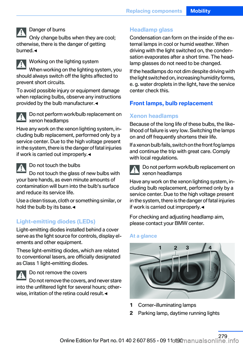
At a glance1Corner-illuminating lamps2Parking lamp, daytime running lightsSeite 279Replacing componentsMobility279
Online Edition for Part no. 01 40 2 607 855 - 09 11 490
Page 284 of 321
Breakdown assistanceVehicle equipment
All standard, country-specific and optional
equipment that is offered in the model series is
described in this chapter. Therefore, equipment
is also described that is not available in a vehicle,
e. g., because of the selected optional equip‐
ment or country variant. This also applies for
safety-related functions and systems.
Hazard warning flashers
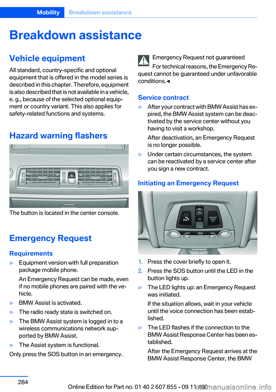
The button is located in the center console.
Emergency Request
Requirements
▷Equipment version with full preparation
package mobile phone.
An Emergency Request can be made, even
if no mobile phones are paired with the ve‐
hicle.▷BMW Assist is activated.▷The radio ready state is switched on.▷The BMW Assist system is logged in to a
wireless communications network sup‐
ported by BMW Assist.▷The Assist system is functional.
Only press the SOS button in an emergency.
Emergency Request not guaranteed
For technical reasons, the Emergency Re‐
quest cannot be guaranteed under unfavorable
conditions.◀
Service contract▷After your contract with BMW Assist has ex‐
pired, the BMW Assist system can be deac‐
tivated by the service center without you
having to visit a workshop.
After deactivation, an Emergency Request
is no longer possible.▷Under certain circumstances, the system
can be reactivated by a service center after
you sign a new contract.
Initiating an Emergency Request
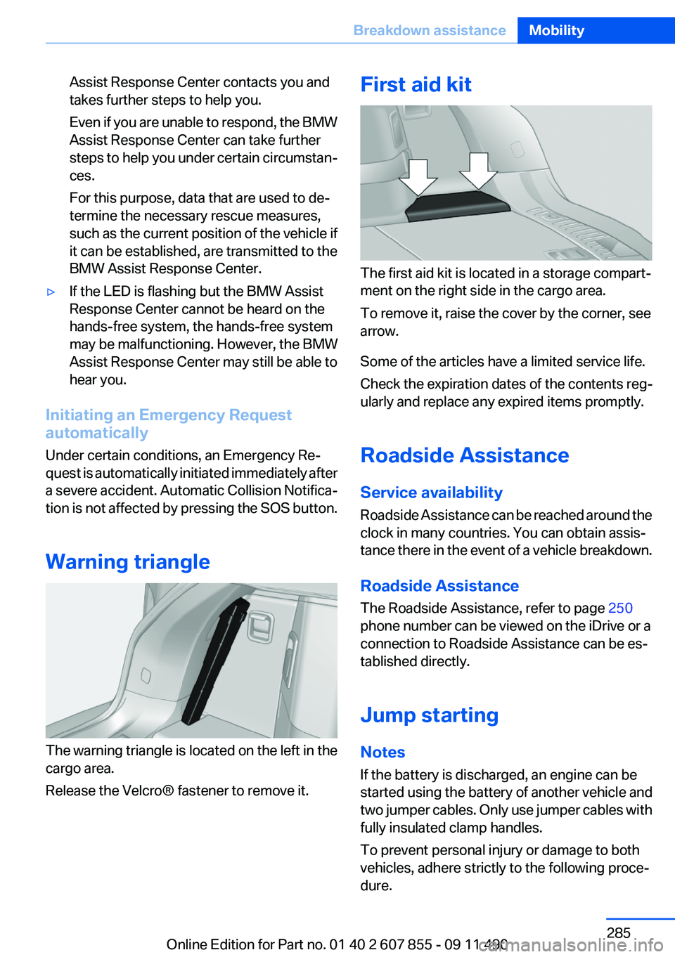
1.Press the cover briefly to open it.2.Press the SOS button until the LED in the
button lights up.▷The LED lights up: an Emergency Request
was initiated.
If the situation allows, wait in your vehicle
until the voice connection has been estab‐
lished.▷The LED flashes if the connection to the
BMW Assist Response Center has been es‐
tablished.
After the Emergency Request arrives at the
BMW Assist Response Center, the BMWSeite 284MobilityBreakdown assistance284
Online Edition for Part no. 01 40 2 607 855 - 09 11 490
Page 285 of 321
Assist Response Center contacts you and
takes further steps to help you.
Even if you are unable to respond, the BMW
Assist Response Center can take further
steps to help you under certain circumstan‐
ces.
For this purpose, data that are used to de‐
termine the necessary rescue measures,
such as the current position of the vehicle if
it can be established, are transmitted to the
BMW Assist Response Center.▷If the LED is flashing but the BMW Assist
Response Center cannot be heard on the
hands-free system, the hands-free system
may be malfunctioning. However, the BMW
Assist Response Center may still be able to
hear you.
Initiating an Emergency Request
automatically
Under certain conditions, an Emergency Re‐
quest is automatically initiated immediately after
a severe accident. Automatic Collision Notifica‐
tion is not affected by pressing the SOS button.
Warning triangle
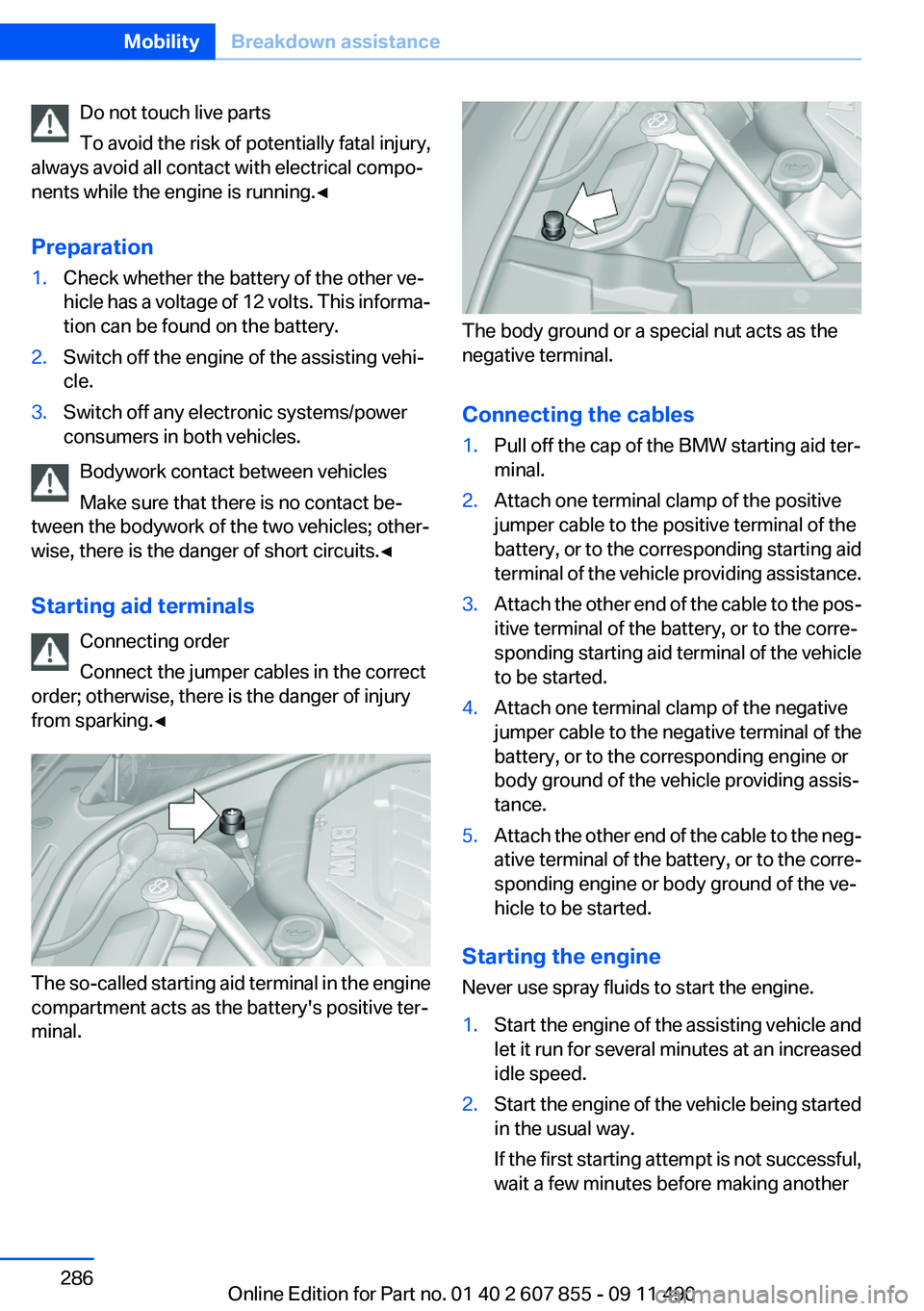
The warning triangle is located on the left in the
cargo area.
Release the Velcro® fastener to remove it.
First aid kit
The first aid kit is located in a storage compart‐
ment on the right side in the cargo area.
To remove it, raise the cover by the corner, see
arrow.
Some of the articles have a limited service life.
Check the expiration dates of the contents reg‐
ularly and replace any expired items promptly.
Roadside Assistance
Service availability
Roadside Assistance can be reached around the
clock in many countries. You can obtain assis‐
tance there in the event of a vehicle breakdown.
Roadside Assistance
The Roadside Assistance, refer to page 250
phone number can be viewed on the iDrive or a
connection to Roadside Assistance can be es‐
tablished directly.
Jump starting
Notes
If the battery is discharged, an engine can be
started using the battery of another vehicle and
two jumper cables. Only use jumper cables with
fully insulated clamp handles.
To prevent personal injury or damage to both
vehicles, adhere strictly to the following proce‐
dure.
Seite 285Breakdown assistanceMobility285
Online Edition for Part no. 01 40 2 607 855 - 09 11 490
Page 286 of 321
Do not touch live parts
To avoid the risk of potentially fatal injury,
always avoid all contact with electrical compo‐
nents while the engine is running.◀
Preparation1.Check whether the battery of the other ve‐
hicle has a voltage of 12 volts. This informa‐
tion can be found on the battery.2.Switch off the engine of the assisting vehi‐
cle.3.Switch off any electronic systems/power
consumers in both vehicles.
Bodywork contact between vehicles
Make sure that there is no contact be‐
tween the bodywork of the two vehicles; other‐
wise, there is the danger of short circuits.◀
Starting aid terminals Connecting order
Connect the jumper cables in the correct
order; otherwise, there is the danger of injury
from sparking.◀
The so-called starting aid terminal in the engine
compartment acts as the battery's positive ter‐
minal.
The body ground or a special nut acts as the
negative terminal.
Connecting the cables
1.Pull off the cap of the BMW starting aid ter‐
minal.2.Attach one terminal clamp of the positive
jumper cable to the positive terminal of the
battery, or to the corresponding starting aid
terminal of the vehicle providing assistance.3.Attach the other end of the cable to the pos‐
itive terminal of the battery, or to the corre‐
sponding starting aid terminal of the vehicle
to be started.4.Attach one terminal clamp of the negative
jumper cable to the negative terminal of the
battery, or to the corresponding engine or
body ground of the vehicle providing assis‐
tance.5.Attach the other end of the cable to the neg‐
ative terminal of the battery, or to the corre‐
sponding engine or body ground of the ve‐
hicle to be started.
Starting the engine
Never use spray fluids to start the engine.
1.Start the engine of the assisting vehicle and
let it run for several minutes at an increased
idle speed.2.Start the engine of the vehicle being started
in the usual way.
If the first starting attempt is not successful,
wait a few minutes before making anotherSeite 286MobilityBreakdown assistance286
Online Edition for Part no. 01 40 2 607 855 - 09 11 490
Page 287 of 321
attempt in order to allow the discharged bat‐
tery to recharge.3.Let both engines run for several minutes.4.Disconnect the jumper cables in the reverse
order.
Check the battery and recharge if necessary.
Tow-starting and towing
Transporting your vehicle
Note
Your vehicle is not permitted to be towed.
Therefore, contact a service center in the event
of a breakdown.
Do not have the vehicle towed
Have your vehicle transported on a loading
platform only; otherwise, damage may occur.◀
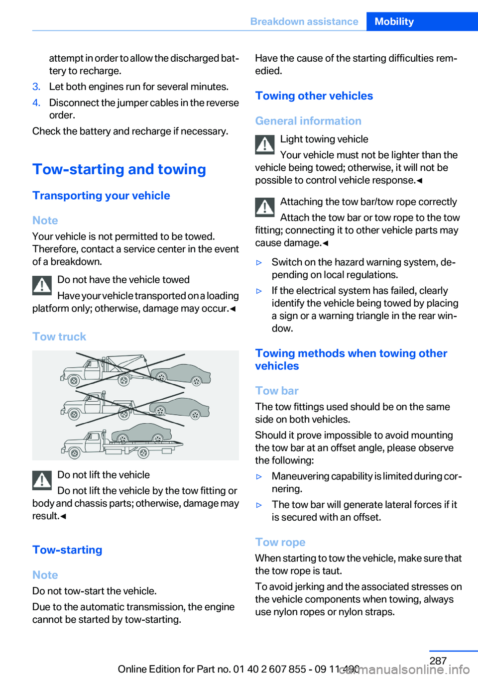
Tow truck
Do not lift the vehicle
Do not lift the vehicle by the tow fitting or
body and chassis parts; otherwise, damage may
result.◀
Tow-starting
Note
Do not tow-start the vehicle.
Due to the automatic transmission, the engine
cannot be started by tow-starting.
Have the cause of the starting difficulties rem‐
edied.
Towing other vehicles
General information Light towing vehicle
Your vehicle must not be lighter than the
vehicle being towed; otherwise, it will not be
possible to control vehicle response.◀
Attaching the tow bar/tow rope correctly
Attach the tow bar or tow rope to the tow
fitting; connecting it to other vehicle parts may
cause damage.◀▷Switch on the hazard warning system, de‐
pending on local regulations.▷If the electrical system has failed, clearly
identify the vehicle being towed by placing
a sign or a warning triangle in the rear win‐
dow.
Towing methods when towing other
vehicles
Tow bar
The tow fittings used should be on the same
side on both vehicles.
Should it prove impossible to avoid mounting
the tow bar at an offset angle, please observe
the following:
▷Maneuvering capability is limited during cor‐
nering.▷The tow bar will generate lateral forces if it
is secured with an offset.
Tow rope
When starting to tow the vehicle, make sure that
the tow rope is taut.
To avoid jerking and the associated stresses on
the vehicle components when towing, always
use nylon ropes or nylon straps.
Seite 287Breakdown assistanceMobility287
Online Edition for Part no. 01 40 2 607 855 - 09 11 490
Page 312 of 321
Concierge service 250
Condensation on win‐ dows 137
Condensation under the vehi‐ cle 160
Condition Based Service CBS 276
Confirmation signal 35
Contacts 239, 247
Control Display 16
Control Display, settings 87
Controller 16
Control systems, driving sta‐ bility 106
Convenient opening 34
Coolant 274
Coolant temperature 82
Cooling function 138
Cooling, maximum 138
Cooling system 274
Corrosion on brake discs 160
Cruise control 121
Cruise control, active with Stop & Go 114
Cruising range 82
Cupholder 152
Curb weight 298
Current fuel consumption 83
Current location, storing 170
Customer Relations 252
D
Damage, tires 266
Damping control, dy‐ namic 109
Data, technical 296
Date 82
Daytime running lights 90
Defrosting, refer to Windows, defrosting 137
Destination distance 85
Destination guidance 176
Destination guidance with in‐ termediate destinations 174 Destination input, naviga‐
tion 168
Digital clock 82
Digital radio 189
Dimensions 296
Dimmable exterior mirrors 61
Dimmable interior rearview mirror 61
Direction indicator, refer to Turn signals 72
Display in front wind‐ shield 134
Display lighting, refer to Instru‐ ment lighting 92
Displays 78
Displays, cleaning 292
Disposal, coolant 275
Disposal, vehicle battery 282
Distance control, refer to PDC 123
Distance, selecting for ACC 116
Distance to destination 85
Divided screen view, split screen 20
Door lock, refer to Remote control 30
Doors, Automatic Soft Clos‐ ing 38
Downhill control 108
Drive-off assistant 106
Drive-off assistant, refer to DSC 106
Driving Experience Switch 110
Driving instructions, breaking in 158
Driving notes, general 158
Driving stability control sys‐ tems 106
Driving tips 158
DSC Dynamic Stability Con‐ trol 106
DTC driving dynamics 107
DTC Dynamic Traction Con‐ trol 107 DVD/CD 196
DVD/CD notes 202
DVD/CD player, rear 217
DVD changer 200
DVD settings 199
DVDs, storing 203
DVD, video 198
Dynamic Damping Con‐ trol 109
Dynamic destination guid‐ ance 182
Dynamic Drive 109
Dynamic Stability Control DSC 106
Dynamic Traction Control DTC 107
E
Electronic displays, instru‐ ment cluster 79
Electronic Stability Program ESP, refer to DSC 106
Emergency detection, remote control 31
Emergency release, door lock 37
Emergency release, fuel filler flap 258
Emergency release, parking brake 69
Emergency Request 284
Emergency service, refer to Roadside Assistance 285
Emergency start function, en‐ gine start 31
Emergency unlocking, tail‐ gate 41
Energy Control 83
Energy recovery 83
Engine compartment 271
Engine compartment, working in 271
Engine coolant 274
Engine oil 273
Engine oil, adding 273 Seite 312ReferenceEverything from A to Z312
Online Edition for Part no. 01 40 2 607 855 - 09 11 490
Page 313 of 321
Engine oil additives 274
Engine oil change 274
Engine oil filler neck 273
Engine oil temperature 81
Engine oil types, alterna‐ tive 274
Engine oil types, ap‐ proved 274
Engine start during malfunc‐ tion 31
Engine start, refer to Starting the engine 68
Engine start, Starting aid 285
Engine stop 68
Engine temperature 81
Entering a car wash 289
Equalizer 186
Equipment, interior 143
ESP Electronic Stability Pro‐ gram, refer to DSC 106
Exchanging wheels/tires 267
Exhaust system 158
Exterior mirror, automatic dim‐ ming feature 61
Exterior mirrors 60
External devices 208
External start 285
External temperature dis‐ play 82
External temperature warn‐ ing 82
Eyes for securing cargo 162
F
Fader 186
Failure message, refer to Check Control 79
False alarm, refer to Uninten‐ tional alarm 44
Fan, refer to Air volume 137
Fault displays, refer to Check Control 79
Filler neck for engine oil 273
Fine wood, care 291
First aid kit 285 Fitting for towing, refer to Tow
fitting 288
Flat tire, changing wheels 282
Flat Tire Monitor FTM 100
Flat tire, Tire Pressure Monitor TPM 97
Flat tire, warning lamp 98, 101
Flooding 159
Floor carpet, care 291
Floor mats, care 291
FM/AM station 188
Fold-out position, windshield wipers 74
Foot brake 159
Front airbags 94
Front fog lamps 92
Front fog lamps, front, bulb re‐ placement 280
Front lamps 279
Front passenger airbags, au‐ tomatic deactivation 96
Front passenger airbags, indi‐ cator lamp 96
FTM Flat Tire Monitor 100
Fuel cap 258
Fuel consumption, current 83
Fuel consumption, refer to Average fuel consump‐
tion 85
Fuel filler flap 258
Fuel gauge 81
Fuel quality 260
Fuel, tank capacity 299
Fuse 283
G
Garage door opener, refer to Integrated universal remote
control 143
Gas station recommenda‐ tion 178
Gear change, automatic trans‐ mission 75
General driving notes 158 Glass sunroof, refer to Panor‐
amic glass sunroof 46
Glove compartment 150
Gong, volume equaliza‐ tion 187
GPS navigation, refer to Navi‐ gation system 168
Gray display of the map 181
Gross vehicle weight, ap‐ proved 298
Gross weight, permissible for trailer towing 298
H
Hand brake, refer to Parking brake 69
Hand-held transmitter, alter‐ nating code 144
Hazard warning flashers 284
HDC Hill Descent Control 108
HD Radio 189
Head airbags 94
Headlamp control, auto‐ matic 90
Headlamp courtesy delay fea‐ ture 90
Headlamp courtesy delay fea‐ ture via remote control 35
Headlamp flasher 73
Headlamp glass 279
Headlamps 279
Headlamps, care 290
Headlamp washer system 73
Headliner 15
Headphones, rear entertain‐ ment 221
Head restraints 49
Head restraints, front 57
Head restraints, rear 58
Head-up Display 134
Head-up Display, care 292
Heavy cargo, stowing 162
Height with roof-mounted aer‐ ial, vehicle 296
High-beam Assistant 91 Seite 313Everything from A to ZReference313
Online Edition for Part no. 01 40 2 607 855 - 09 11 490