2012 BMW 535I GRAN TURISMO check engine light
[x] Cancel search: check engine lightPage 80 of 321
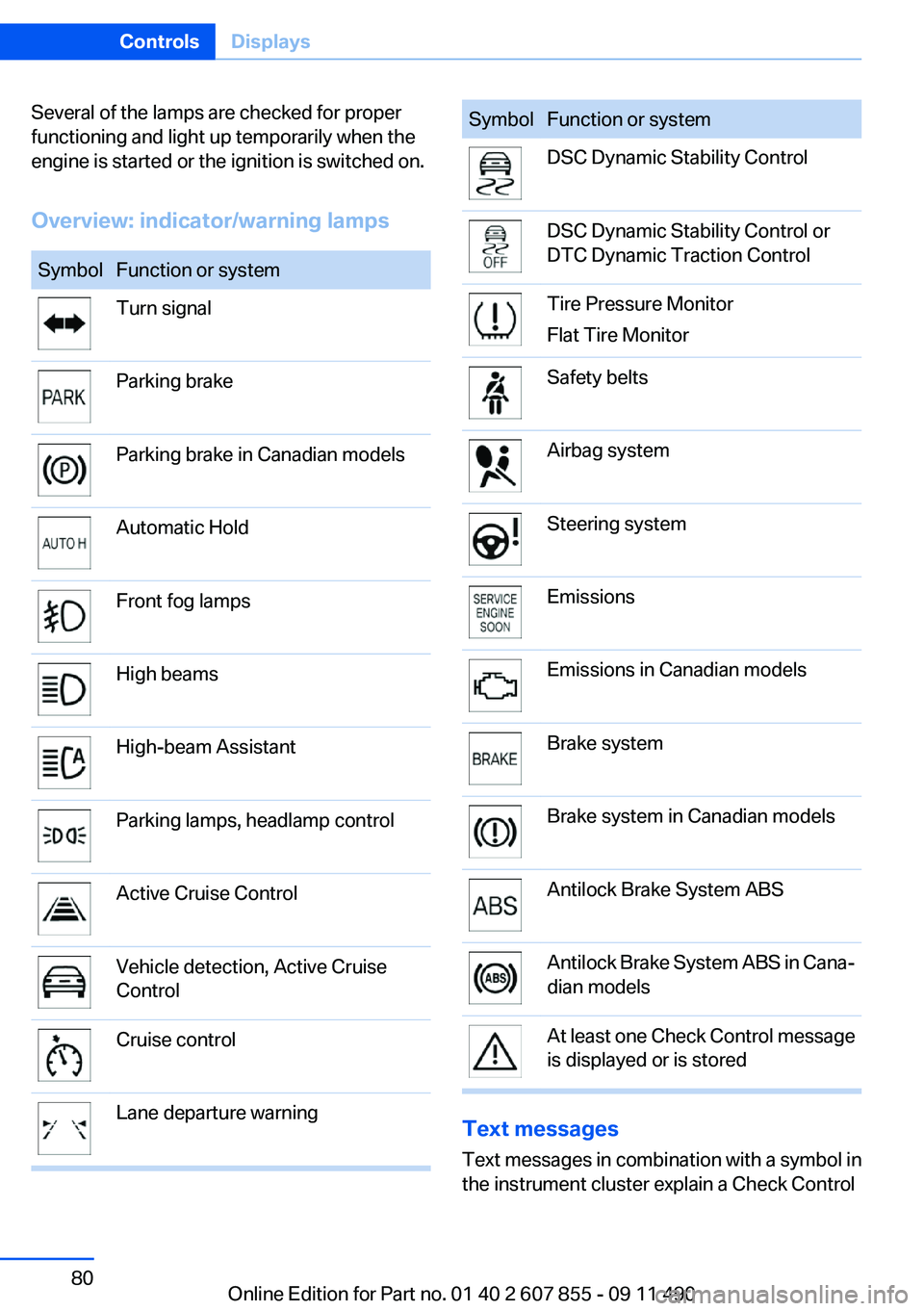
Several of the lamps are checked for proper
functioning and light up temporarily when the
engine is started or the ignition is switched on.
Overview: indicator/warning lampsSymbolFunction or systemTurn signalParking brakeParking brake in Canadian modelsAutomatic HoldFront fog lampsHigh beamsHigh-beam AssistantParking lamps, headlamp controlActive Cruise ControlVehicle detection, Active Cruise
ControlCruise controlLane departure warningSymbolFunction or systemDSC Dynamic Stability ControlDSC Dynamic Stability Control or
DTC Dynamic Traction ControlTire Pressure Monitor
Flat Tire MonitorSafety beltsAirbag systemSteering systemEmissionsEmissions in Canadian modelsBrake systemBrake system in Canadian modelsAntilock Brake System ABSAntilock Brake System ABS in Cana‐
dian modelsAt least one Check Control message
is displayed or is stored
Text messages
Text messages in combination with a symbol in
the instrument cluster explain a Check Control
Seite 80ControlsDisplays80
Online Edition for Part no. 01 40 2 607 855 - 09 11 490
Page 98 of 321
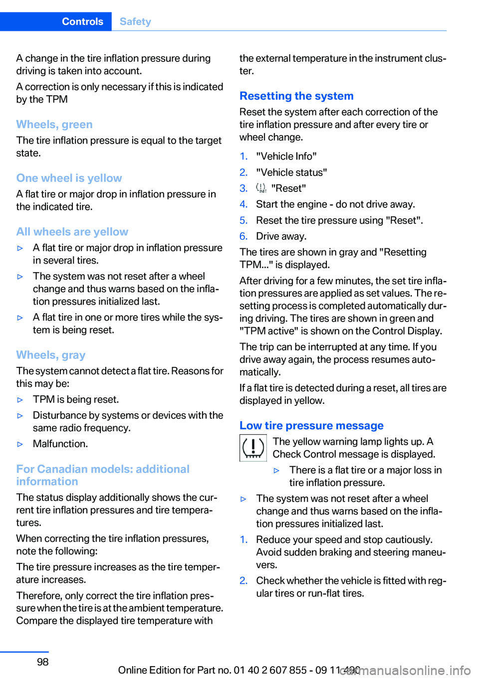
A change in the tire inflation pressure during
driving is taken into account.
A correction is only necessary if this is indicated
by the TPM
Wheels, green
The tire inflation pressure is equal to the target
state.
One wheel is yellow
A flat tire or major drop in inflation pressure in
the indicated tire.
All wheels are yellow▷A flat tire or major drop in inflation pressure
in several tires.▷The system was not reset after a wheel
change and thus warns based on the infla‐
tion pressures initialized last.▷A flat tire in one or more tires while the sys‐
tem is being reset.
Wheels, gray
The system cannot detect a flat tire. Reasons for
this may be:
▷TPM is being reset.▷Disturbance by systems or devices with the
same radio frequency.▷Malfunction.
For Canadian models: additional
information
The status display additionally shows the cur‐
rent tire inflation pressures and tire tempera‐
tures.
When correcting the tire inflation pressures,
note the following:
The tire pressure increases as the tire temper‐
ature increases.
Therefore, only correct the tire inflation pres‐
sure when the tire is at the ambient temperature.
Compare the displayed tire temperature with
the external temperature in the instrument clus‐
ter.
Resetting the system
Reset the system after each correction of the
tire inflation pressure and after every tire or
wheel change.1."Vehicle Info"2."Vehicle status"3. "Reset"4.Start the engine - do not drive away.5.Reset the tire pressure using "Reset".6.Drive away.
The tires are shown in gray and "Resetting
TPM..." is displayed.
After driving for a few minutes, the set tire infla‐
tion pressures are applied as set values. The re‐
setting process is completed automatically dur‐
ing driving. The tires are shown in green and
"TPM active" is shown on the Control Display.
The trip can be interrupted at any time. If you
drive away again, the process resumes auto‐
matically.
If a flat tire is detected during a reset, all tires are
displayed in yellow.
Low tire pressure message The yellow warning lamp lights up. A
Check Control message is displayed.
▷There is a flat tire or a major loss in
tire inflation pressure.▷The system was not reset after a wheel
change and thus warns based on the infla‐
tion pressures initialized last.1.Reduce your speed and stop cautiously.
Avoid sudden braking and steering maneu‐
vers.2.Check whether the vehicle is fitted with reg‐
ular tires or run-flat tires.Seite 98ControlsSafety98
Online Edition for Part no. 01 40 2 607 855 - 09 11 490
Page 101 of 321
In the event of a pressure loss, the diameter and
therefore the rotational speed of the corre‐
sponding wheel change. This is detected and
reported as a flat tire.
Functional requirements
The system must have been initialized when the
tire inflation pressure was correct; otherwise,
reliable signaling of a flat tire is not ensured. In‐
itialize the system after each correction of the
tire inflation pressure and after every tire or
wheel change.
System limits Sudden tire damage
Sudden serious tire damage caused by
external influences cannot be indicated in ad‐
vance.◀
A natural, even pressure loss in all four tires can‐
not be detected. Therefore, check the tire infla‐
tion pressure regularly.
The system could be delayed or malfunction in
the following situations:▷When the system has not been initialized.▷When driving on a snowy or slippery road
surface.▷Sporty driving style: slip in the drive wheels,
high lateral acceleration.▷When driving with snow chains.
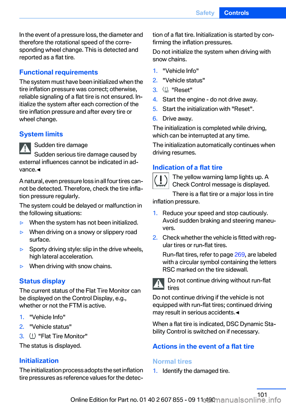
Status display
The current status of the Flat Tire Monitor can
be displayed on the Control Display, e.g.,
whether or not the FTM is active.
1."Vehicle Info"2."Vehicle status"3. "Flat Tire Monitor"
The status is displayed.
Initialization
The initialization process adopts the set inflation
tire pressures as reference values for the detec‐
tion of a flat tire. Initialization is started by con‐
firming the inflation pressures.
Do not initialize the system when driving with
snow chains.1."Vehicle Info"2."Vehicle status"3. "Reset"4.Start the engine - do not drive away.5.Start the initialization with "Reset".6.Drive away.
The initialization is completed while driving,
which can be interrupted at any time.
The initialization automatically continues when
driving resumes.
Indication of a flat tire The yellow warning lamp lights up. A
Check Control message is displayed.
There is a flat tire or a major loss in tire
inflation pressure.
1.Reduce your speed and stop cautiously.
Avoid sudden braking and steering maneu‐
vers.2.Check whether the vehicle is fitted with reg‐
ular tires or run-flat tires.
Run-flat tires, refer to page 269, are labeled
with a circular symbol containing the letters
RSC marked on the tire sidewall.
Do not continue driving without run-flat
tires
Do not continue driving if the vehicle is not
equipped with run-flat tires; continued driving
may result in serious accidents.◀
When a flat tire is indicated, DSC Dynamic Sta‐
bility Control is switched on if necessary.
Actions in the event of a flat tire
Normal tires
1.Identify the damaged tire.Seite 101SafetyControls101
Online Edition for Part no. 01 40 2 607 855 - 09 11 490
Page 110 of 321
At speeds up to approx. 37 mph/60 km/h, e.g.,
in curves, the steering angle is increased, i.e.,
steering becomes more direct.
The rear axle steering acts to increase maneu‐
verability by turning the rear wheels slightly in a
direction opposite to the front wheels.
At higher speeds, the steering angle is increas‐
ingly reduced.
The rear wheels are turned to the same angle as
the front wheels.
In critical situations, Integral Active Steering can
specifically steer the front and rear wheels to
stabilize the vehicle before the driver intervenes,
e.g., when braking where road conditions differ
on the left and right sides of the vehicle.
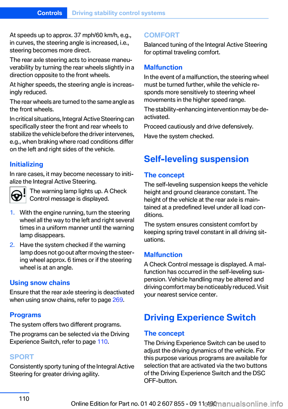
Initializing
In rare cases, it may become necessary to initi‐
alize the Integral Active Steering.
The warning lamp lights up. A Check
Control message is displayed.1.With the engine running, turn the steering
wheel all the way to the left and right several
times in a uniform manner until the warning
lamp disappears.2.Have the system checked if the warning
lamp does not go out after moving the steer‐
ing wheel approx. 6 times or if the steering
wheel is at an angle.
Using snow chains
Ensure that the rear axle steering is deactivated
when using snow chains, refer to page 269.
Programs
The system offers two different programs.
The programs can be selected via the Driving
Experience Switch, refer to page 110.
SPORT
Consistently sporty tuning of the Integral Active
Steering for greater driving agility.
COMFORT
Balanced tuning of the Integral Active Steering
for optimal traveling comfort.
Malfunction
In the event of a malfunction, the steering wheel
must be turned further, while the vehicle re‐
sponds more sensitively to steering wheel
movements in the higher speed range.
The stability-enhancing intervention may be de‐
activated.
Proceed cautiously and drive defensively.
Have the system checked.
Self-leveling suspension
The concept
The self-leveling suspension keeps the vehicle
height and ground clearance constant. The
height of the vehicle at the rear axle is main‐
tained at a predefined level under all load con‐
ditions.
The system ensures consistent comfort by
keeping spring travel constant in all driving sit‐
uations.
Malfunction
A Check Control message is displayed. A mal‐
function has occurred in the self-leveling sus‐
pension. Vehicle handling may be altered and
driving comfort may be noticeably reduced. Visit
your nearest service center.
Driving Experience Switch
The concept
The Driving Experience Switch can be used to
adjust the driving dynamics of the vehicle. For
this purpose various programs are available for
selection that are activated via the two buttons
of the Driving Experience Switch and the DSC
OFF-button.Seite 110ControlsDriving stability control systems110
Online Edition for Part no. 01 40 2 607 855 - 09 11 490
Page 116 of 321
DistanceSelecting a distance
Adjust the distance according to the traffic
and weather conditions; otherwise, there is the
danger of an accident occurring. Maintain the
prescribed safety distance.◀
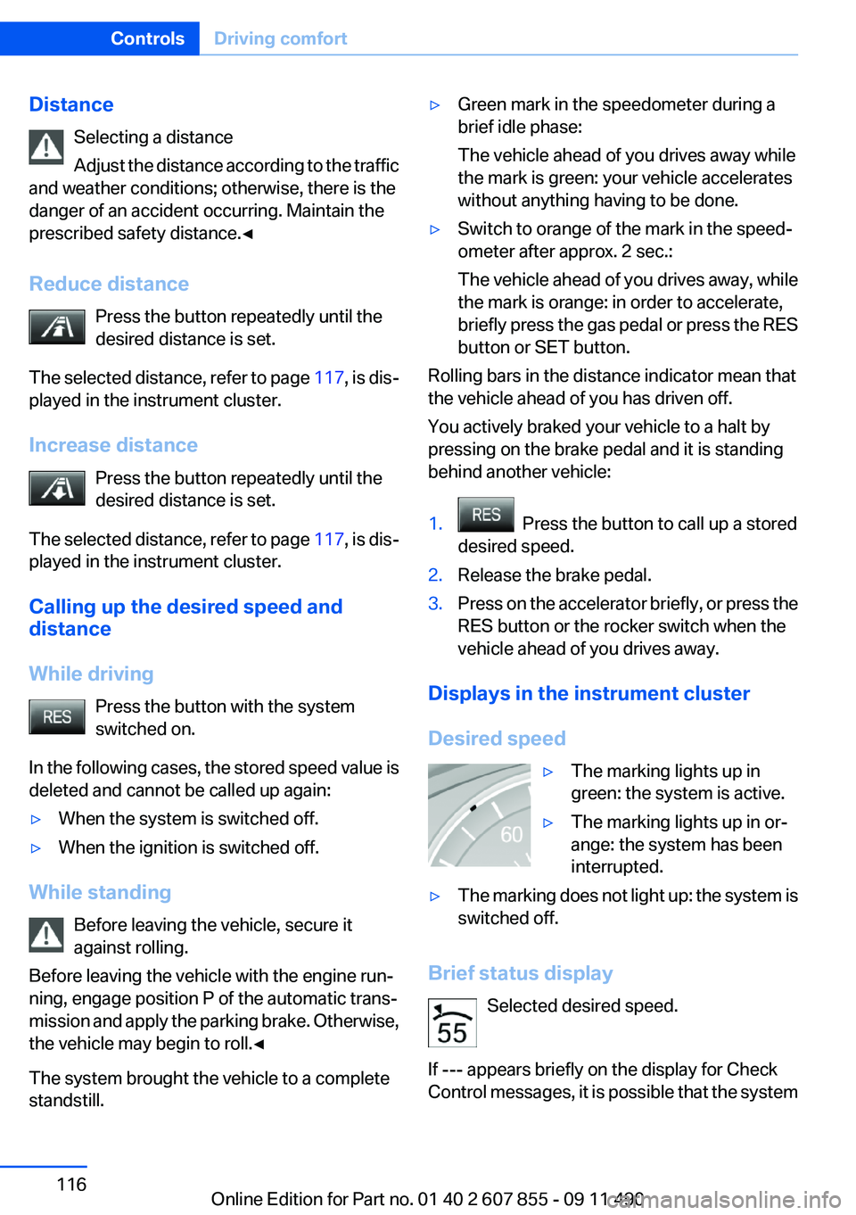
Reduce distance Press the button repeatedly until the
desired distance is set.
The selected distance, refer to page 117, is dis‐
played in the instrument cluster.
Increase distance Press the button repeatedly until the
desired distance is set.
The selected distance, refer to page 117, is dis‐
played in the instrument cluster.
Calling up the desired speed and
distance
While driving Press the button with the system
switched on.
In the following cases, the stored speed value is
deleted and cannot be called up again:▷When the system is switched off.▷When the ignition is switched off.
While standing
Before leaving the vehicle, secure it
against rolling.
Before leaving the vehicle with the engine run‐
ning, engage position P of the automatic trans‐
mission and apply the parking brake. Otherwise,
the vehicle may begin to roll.◀
The system brought the vehicle to a complete
standstill.
▷Green mark in the speedometer during a
brief idle phase:
The vehicle ahead of you drives away while
the mark is green: your vehicle accelerates
without anything having to be done.▷Switch to orange of the mark in the speed‐
ometer after approx. 2 sec.:
The vehicle ahead of you drives away, while
the mark is orange: in order to accelerate,
briefly press the gas pedal or press the RES
button or SET button.
Rolling bars in the distance indicator mean that
the vehicle ahead of you has driven off.
You actively braked your vehicle to a halt by
pressing on the brake pedal and it is standing
behind another vehicle:
1. Press the button to call up a stored
desired speed.2.Release the brake pedal.3.Press on the accelerator briefly, or press the
RES button or the rocker switch when the
vehicle ahead of you drives away.
Displays in the instrument cluster
Desired speed
▷The marking lights up in
green: the system is active.▷The marking lights up in or‐
ange: the system has been
interrupted.▷The marking does not light up: the system is
switched off.
Brief status display
Selected desired speed.
If --- appears briefly on the display for Check
Control messages, it is possible that the system
Seite 116ControlsDriving comfort116
Online Edition for Part no. 01 40 2 607 855 - 09 11 490
Page 124 of 321
System limitsCheck the traffic situation as well
PDC cannot serve as a substitute for the
driver's personal judgment of the traffic situa‐
tion. Check the traffic situation around the vehi‐
cle with your own eyes. Otherwise, an accident
could result from road users or objects located
outside of the PDC detection range.
Loud noises from outside and inside the vehicle
may prevent you from hearing the PDC's signal
tone.◀
Avoid driving quickly with PDC
Avoid approaching an object quickly.
Avoid driving away quickly while PDC is not yet
active.
For technical reasons, the system may other‐
wise be too late in issuing a warning.◀
Limits of ultrasonic measurement
The detection of objects can reach the physical
limits of ultrasonic measurement, e.g.:▷With tow bars and trailer hitches.▷With thin or wedge-shaped objects.▷With low objects.▷With objects with corners and sharp edges.
Low objects already displayed, e.g., curbs, can
move into the blind area of the sensors before or
after a continuous tone sounds.
High, protruding objects such as ledges may not
be detected.
False warnings
PDC may issue a warning under the following
conditions even though there is no obstacle
within the detection range:
▷In heavy rain.▷When sensors are very dirty or covered in
ice.▷When sensors are covered in snow.▷On rough road surfaces.▷In large buildings with right angles and
smooth walls, e.g., in underground garages.▷In heavy exhaust.▷Due to other ultrasound sources, e.g.,
sweeping machines, high pressure steam
cleaners or neon lights.
Switching on automatically
Select transmission position R with the engine
running.
Switching off automatically
The system switches off and the LED goes out:
▷After approx. 160 ft/50 m when driving for‐
ward.▷Above approx. 22 mph/36 km/h when driv‐
ing forward.
Switch on the system again if necessary.
Switching on/off manually
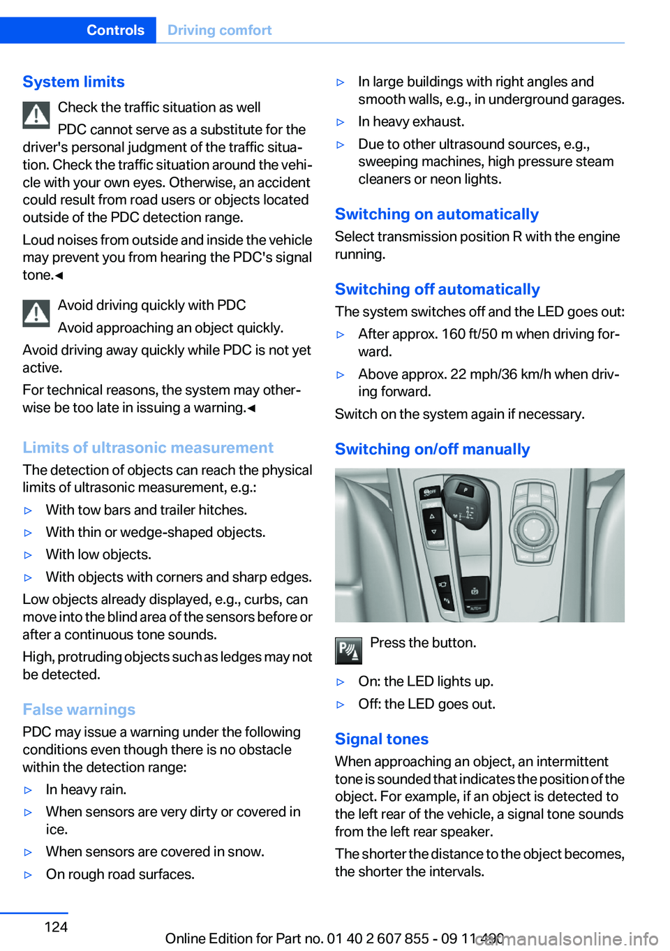
Press the button.
▷On: the LED lights up.▷Off: the LED goes out.
Signal tones
When approaching an object, an intermittent
tone is sounded that indicates the position of the
object. For example, if an object is detected to
the left rear of the vehicle, a signal tone sounds
from the left rear speaker.
The shorter the distance to the object becomes,
the shorter the intervals.
Seite 124ControlsDriving comfort124
Online Edition for Part no. 01 40 2 607 855 - 09 11 490
Page 126 of 321
▷When using a pressure washer, keep the
sprayer moving and maintain a distance of
at least 12 in/30 cm from the sensors.
Surround View
The concept
Surround View includes the following systems:
▷Backup camera, refer to page 127.▷Side View, refer to page 130.▷Top View, refer to page 126.
It assists the driver when parking, maneuvering
and on blind driveways and intersections.
Top View
The concept
Top View assists you in parking and maneuver‐
ing. The area around the doors and the road area
around the vehicle are shown on the Control
Display for this purpose.
Capturing the image
The image is captured by two cameras
integrated in the exterior mirrors and by the
backup camera.
The range equals:
▷approx. 10 ft/3 m to the side.▷approx. 7 ft/2 m to the rear.
In this way, obstacles up to the height of the ex‐
terior mirrors are detected early.
System limits
Top View cannot be used in the following situa‐
tions:
▷With a door open.▷With the tailgate open.▷With an exterior mirror folded in.▷In poor light.A Check Control message is displayed in some
of these situations.
Check the traffic situation as well
Check the traffic situation around the ve‐
hicle with your own eyes. Otherwise, an accident
could result from road users or objects located
outside the picture area of the cameras.◀
Switching on automatically
Select transmission position R with the engine
running.
The Top View and PDC images are displayed if
the system is switched on via iDrive.
Automatic deactivation during forward
travel
The system switches off when a certain driving
distance or speed is exceeded.
Switch the system back on if necessary.
Switching on/off manually
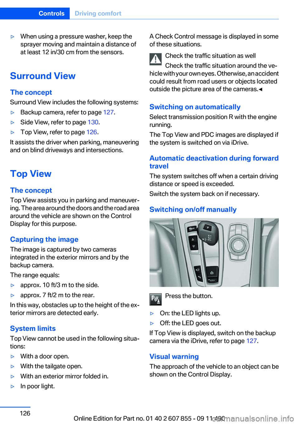
Press the button.
▷On: the LED lights up.▷Off: the LED goes out.
If Top View is displayed, switch on the backup
camera via the iDrive, refer to page 127.
Visual warning
The approach of the vehicle to an object can be
shown on the Control Display.
Seite 126ControlsDriving comfort126
Online Edition for Part no. 01 40 2 607 855 - 09 11 490
Page 128 of 321
System limitsCheck the traffic situation as well
Check the traffic situation around the ve‐
hicle with your own eyes. Otherwise, an accident
could result from road users or objects located
outside the picture area of the backup camera. ◀
Detection of objects
High, protruding objects such as ledges
may not be detected by the backup camera.◀
Switching on automatically
Select transmission position R with the engine
running.
The backup camera image is displayed if the
system was switched on via the iDrive.
Automatic deactivation during forward
travel
The system switches off when a certain driving
distance or speed is exceeded.
Switch the system back on if necessary.
Switching on/off manually
Press the button.
▷On: the LED lights up.▷Off: the LED goes out.
The PDC is shown on the Control Display.
Switch on the backup camera via the iDrive, refer
to page 129.
Assistance functions
Functional requirement▷The backup camera is switched on.▷The tailgate is fully closed.
Pathway lines
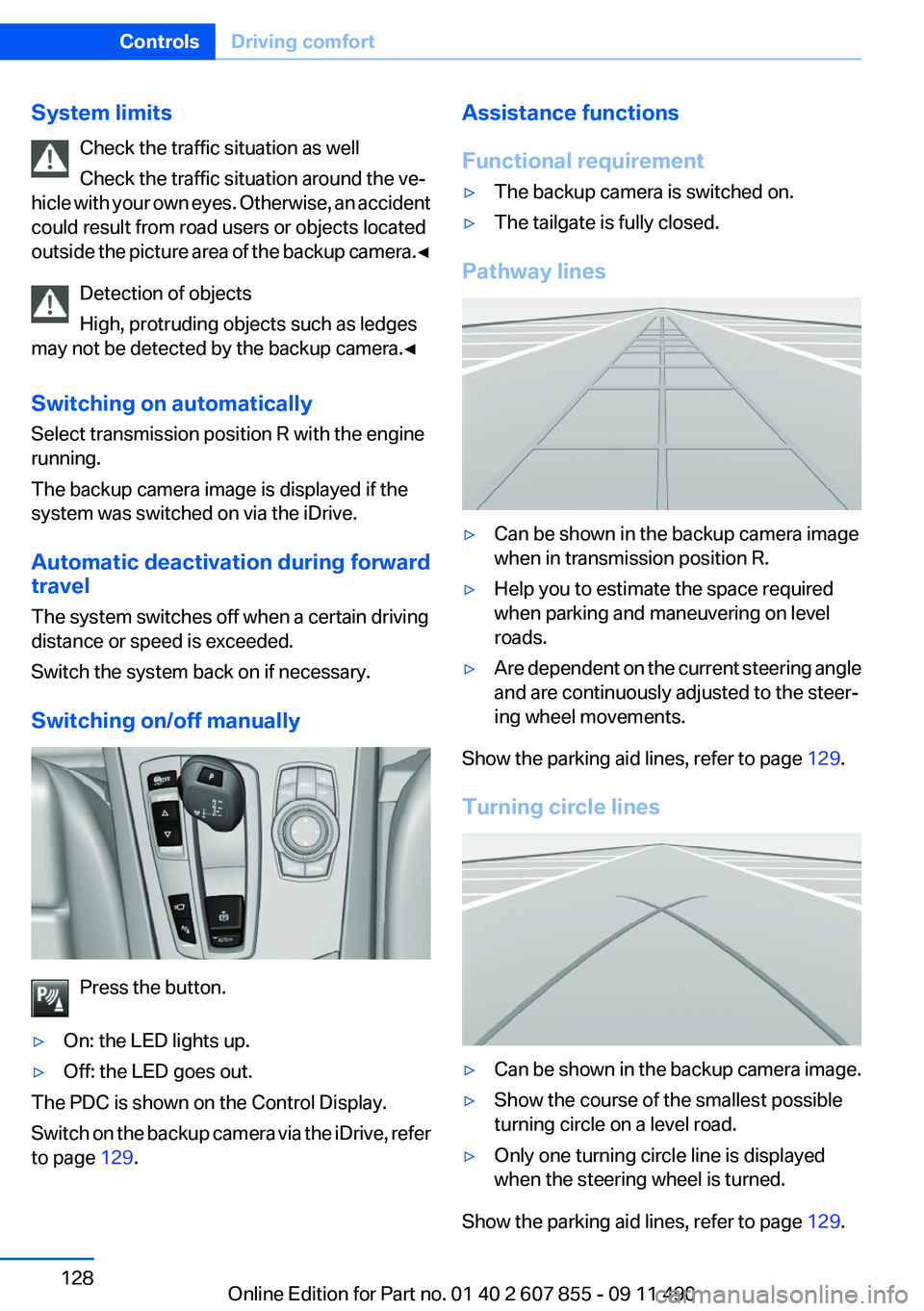
▷Can be shown in the backup camera image
when in transmission position R.▷Help you to estimate the space required
when parking and maneuvering on level
roads.▷Are dependent on the current steering angle
and are continuously adjusted to the steer‐
ing wheel movements.
Show the parking aid lines, refer to page 129.
Turning circle lines
▷Can be shown in the backup camera image.▷Show the course of the smallest possible
turning circle on a level road.▷Only one turning circle line is displayed
when the steering wheel is turned.
Show the parking aid lines, refer to page 129.
Seite 128ControlsDriving comfort128
Online Edition for Part no. 01 40 2 607 855 - 09 11 490