2012 BMW 528I SEDAN warning
[x] Cancel search: warningPage 125 of 335
The intermittent tone is interrupted after approx.
3 seconds:▷If the vehicle stops in front of an object that
is detected by only one of the corner sen‐
sors.▷If moving parallel to a wall.
The signal tone is switched off:
▷When the vehicle moves away from an ob‐
ject by more than approx. 4 in/10 cm.▷When transmission position P is engaged.
Volume
You can set the volume of the PDC signal tone,
refer to page 191.
The setting is stored for the remote control cur‐
rently in use.
Visual warning
The approach of the vehicle to an object can be
shown on the Control Display. Objects that are
farther away are displayed on the Control Dis‐
play before a signal tone sounds.
A display appears as soon as Park Distance
Control (PDC) is activated.
If the backup camera image was selected last, it
again appears on the display. To switch to PDC:
1. "Rear view camera" Select the symbol
on the Control Display.2.Press the controller.
The setting is stored for the remote control cur‐
rently in use.
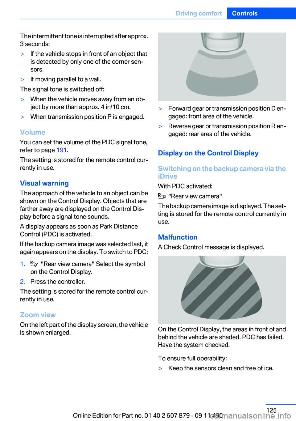
Zoom view
On the left part of the display screen, the vehicle
is shown enlarged.
▷Forward gear or transmission position D en‐
gaged: front area of the vehicle.▷Reverse gear or transmission position R en‐
gaged: rear area of the vehicle.
Display on the Control Display
Switching on the backup camera via the
iDrive
With PDC activated:
"Rear view camera"
The backup camera image is displayed. The set‐
ting is stored for the remote control currently in
use.
Malfunction
A Check Control message is displayed.
On the Control Display, the areas in front of and
behind the vehicle are shaded. PDC has failed.
Have the system checked.
To ensure full operability:
▷Keep the sensors clean and free of ice.Seite 125Driving comfortControls125
Online Edition for Part no. 01 40 2 607 879 - 09 11 490
Page 129 of 335
Automatic deactivation during forward
travel
The system switches off when a certain driving
distance or speed is exceeded.
Switch the system back on if necessary.
Switching on/off manually
Press the button.
▷On: the LED lights up.▷Off: the LED goes out.
If Top View is displayed, switch on the backup
camera via the iDrive, refer to page 129.
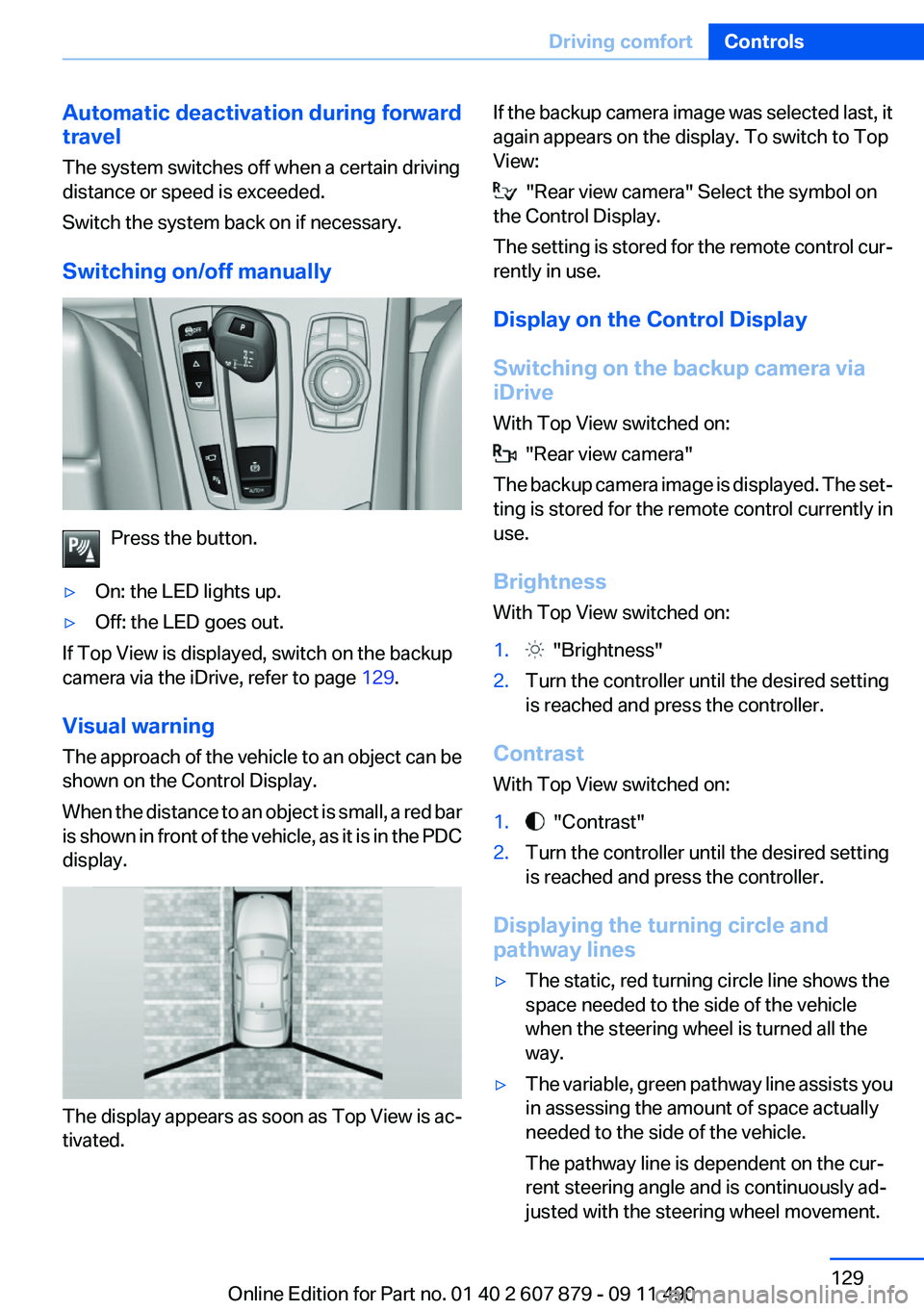
Visual warning
The approach of the vehicle to an object can be
shown on the Control Display.
When the distance to an object is small, a red bar
is shown in front of the vehicle, as it is in the PDC
display.
The display appears as soon as Top View is ac‐
tivated.
If the backup camera image was selected last, it
again appears on the display. To switch to Top
View:
"Rear view camera" Select the symbol on
the Control Display.
The setting is stored for the remote control cur‐
rently in use.
Display on the Control Display
Switching on the backup camera via
iDrive
With Top View switched on:
"Rear view camera"
The backup camera image is displayed. The set‐
ting is stored for the remote control currently in
use.
Brightness
With Top View switched on:
1. "Brightness"2.Turn the controller until the desired setting
is reached and press the controller.
Contrast
With Top View switched on:
1. "Contrast"2.Turn the controller until the desired setting
is reached and press the controller.
Displaying the turning circle and
pathway lines
▷The static, red turning circle line shows the
space needed to the side of the vehicle
when the steering wheel is turned all the
way.▷The variable, green pathway line assists you
in assessing the amount of space actually
needed to the side of the vehicle.
The pathway line is dependent on the cur‐
rent steering angle and is continuously ad‐
justed with the steering wheel movement.Seite 129Driving comfortControls129
Online Edition for Part no. 01 40 2 607 879 - 09 11 490
Page 135 of 335
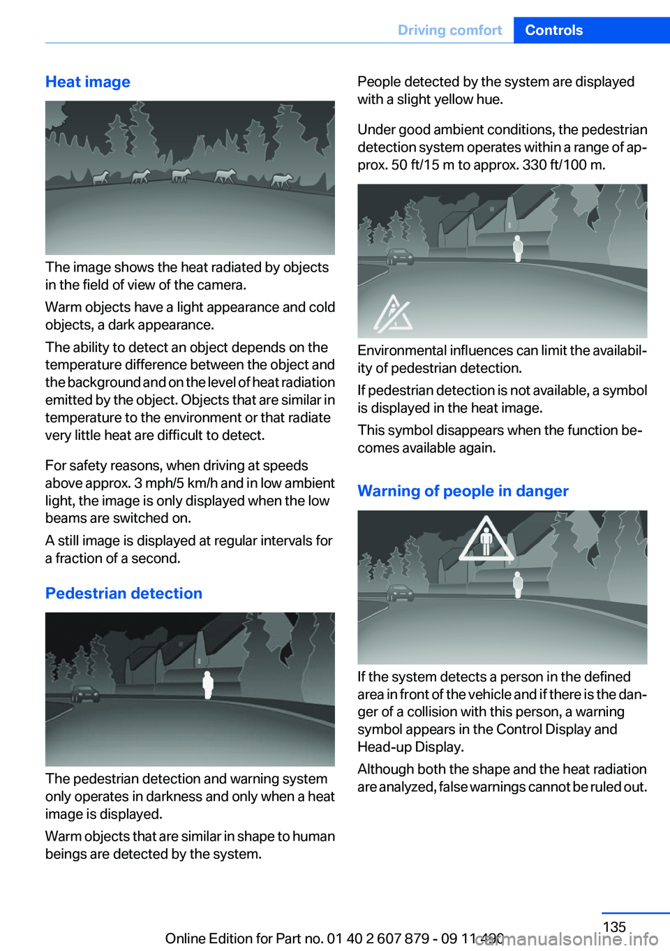
Heat image
The image shows the heat radiated by objects
in the field of view of the camera.
Warm objects have a light appearance and cold
objects, a dark appearance.
The ability to detect an object depends on the
temperature difference between the object and
the background and on the level of heat radiation
emitted by the object. Objects that are similar in
temperature to the environment or that radiate
very little heat are difficult to detect.
For safety reasons, when driving at speeds
above approx. 3 mph/5 km/h and in low ambient
light, the image is only displayed when the low
beams are switched on.
A still image is displayed at regular intervals for
a fraction of a second.
Pedestrian detection
The pedestrian detection and warning system
only operates in darkness and only when a heat
image is displayed.
Warm objects that are similar in shape to human
beings are detected by the system.
People detected by the system are displayed
with a slight yellow hue.
Under good ambient conditions, the pedestrian
detection system operates within a range of ap‐
prox. 50 ft/15 m to approx. 330 ft/100 m.
Environmental influences can limit the availabil‐
ity of pedestrian detection.
If pedestrian detection is not available, a symbol
is displayed in the heat image.
This symbol disappears when the function be‐
comes available again.
Warning of people in danger
If the system detects a person in the defined
area in front of the vehicle and if there is the dan‐
ger of a collision with this person, a warning
symbol appears in the Control Display and
Head-up Display.
Although both the shape and the heat radiation
are analyzed, false warnings cannot be ruled out.
Seite 135Driving comfortControls135
Online Edition for Part no. 01 40 2 607 879 - 09 11 490
Page 136 of 335
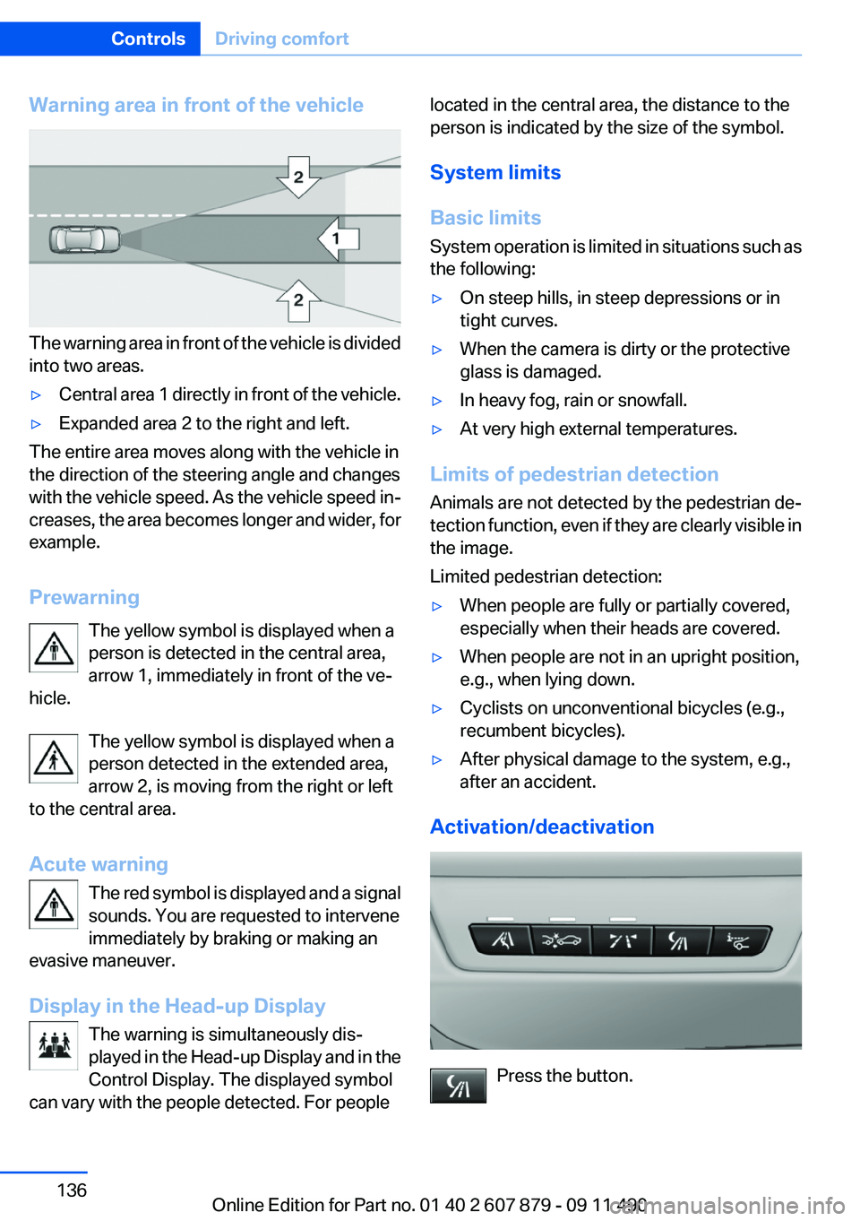
Warning area in front of the vehicle
The warning area in front of the vehicle is divided
into two areas.
▷Central area 1 directly in front of the vehicle.▷Expanded area 2 to the right and left.
The entire area moves along with the vehicle in
the direction of the steering angle and changes
with the vehicle speed. As the vehicle speed in‐
creases, the area becomes longer and wider, for
example.
Prewarning The yellow symbol is displayed when a
person is detected in the central area,
arrow 1, immediately in front of the ve‐
hicle.
The yellow symbol is displayed when a
person detected in the extended area,
arrow 2, is moving from the right or left
to the central area.
Acute warning The red symbol is displayed and a signal
sounds. You are requested to intervene
immediately by braking or making an
evasive maneuver.
Display in the Head-up Display The warning is simultaneously dis‐
played in the Head-up Display and in the
Control Display. The displayed symbol
can vary with the people detected. For people
located in the central area, the distance to the
person is indicated by the size of the symbol.
System limits
Basic limits
System operation is limited in situations such as
the following:▷On steep hills, in steep depressions or in
tight curves.▷When the camera is dirty or the protective
glass is damaged.▷In heavy fog, rain or snowfall.▷At very high external temperatures.
Limits of pedestrian detection
Animals are not detected by the pedestrian de‐
tection function, even if they are clearly visible in
the image.
Limited pedestrian detection:
▷When people are fully or partially covered,
especially when their heads are covered.▷When people are not in an upright position,
e.g., when lying down.▷Cyclists on unconventional bicycles (e.g.,
recumbent bicycles).▷After physical damage to the system, e.g.,
after an accident.
Activation/deactivation
Press the button.
Seite 136ControlsDriving comfort136
Online Edition for Part no. 01 40 2 607 879 - 09 11 490
Page 138 of 335
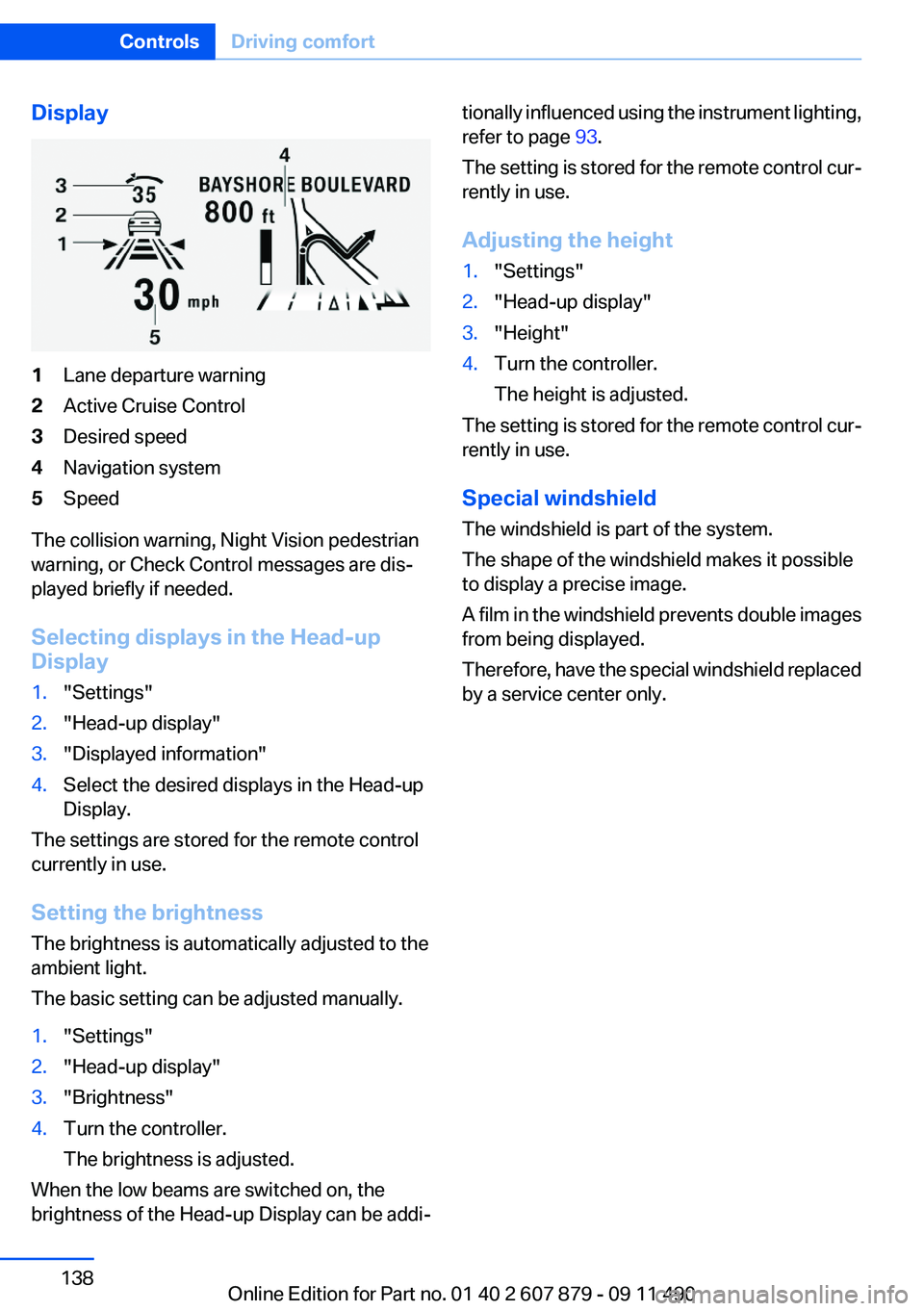
Display1Lane departure warning2Active Cruise Control3Desired speed4Navigation system5Speed
The collision warning, Night Vision pedestrian
warning, or Check Control messages are dis‐
played briefly if needed.
Selecting displays in the Head-up
Display
1."Settings"2."Head-up display"3."Displayed information"4.Select the desired displays in the Head-up
Display.
The settings are stored for the remote control
currently in use.
Setting the brightness
The brightness is automatically adjusted to the
ambient light.
The basic setting can be adjusted manually.
1."Settings"2."Head-up display"3."Brightness"4.Turn the controller.
The brightness is adjusted.
When the low beams are switched on, the
brightness of the Head-up Display can be addi‐
tionally influenced using the instrument lighting,
refer to page 93.
The setting is stored for the remote control cur‐
rently in use.
Adjusting the height1."Settings"2."Head-up display"3."Height"4.Turn the controller.
The height is adjusted.
The setting is stored for the remote control cur‐
rently in use.
Special windshield
The windshield is part of the system.
The shape of the windshield makes it possible
to display a precise image.
A film in the windshield prevents double images
from being displayed.
Therefore, have the special windshield replaced
by a service center only.
Seite 138ControlsDriving comfort138
Online Edition for Part no. 01 40 2 607 879 - 09 11 490
Page 168 of 335
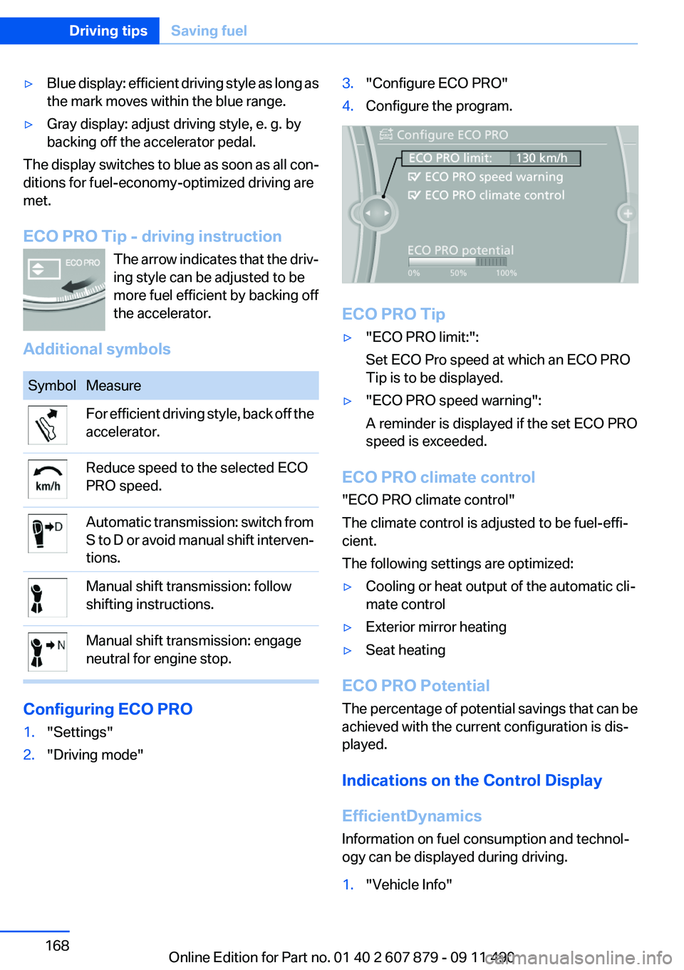
▷Blue display: efficient driving style as long as
the mark moves within the blue range.▷Gray display: adjust driving style, e. g. by
backing off the accelerator pedal.
The display switches to blue as soon as all con‐
ditions for fuel-economy-optimized driving are
met.
ECO PRO Tip - driving instruction The arrow indicates that the driv‐
ing style can be adjusted to be
more fuel efficient by backing off
the accelerator.
Additional symbols
SymbolMeasureFor efficient driving style, back off the
accelerator.Reduce speed to the selected ECO
PRO speed.Automatic transmission: switch from
S to D or avoid manual shift interven‐
tions.Manual shift transmission: follow
shifting instructions.Manual shift transmission: engage
neutral for engine stop.
Configuring ECO PRO
1."Settings"2."Driving mode"3."Configure ECO PRO"4.Configure the program.
ECO PRO Tip
▷"ECO PRO limit:":
Set ECO Pro speed at which an ECO PRO
Tip is to be displayed.▷"ECO PRO speed warning":
A reminder is displayed if the set ECO PRO
speed is exceeded.
ECO PRO climate control
"ECO PRO climate control"
The climate control is adjusted to be fuel-effi‐
cient.
The following settings are optimized:
▷Cooling or heat output of the automatic cli‐
mate control▷Exterior mirror heating▷Seat heating
ECO PRO Potential
The percentage of potential savings that can be
achieved with the current configuration is dis‐
played.
Indications on the Control Display
EfficientDynamics
Information on fuel consumption and technol‐
ogy can be displayed during driving.
1."Vehicle Info"Seite 168Driving tipsSaving fuel168
Online Edition for Part no. 01 40 2 607 879 - 09 11 490
Page 285 of 335
▷"Engine oil at minimum. Add 1 quart of
engine oil!"
Within the next 125 miles/200 km, a maxi‐
mum of 1 US quart/liter oil.▷"Engine oil level below minimum. Add 1
quart!"
Immediately add 1 US quart/liter of oil.
Detailed measurement
Requirements:
▷Vehicle is on a level road and the engine is
running at operating temperature.▷Manual transmission: Shift lever in neutral
position clutch and gas pedal not de‐
pressed.▷Automatic transmission: Selector lever in
transmission position N or P and gas pedal
not depressed.
In order to perform a detailed measurement of
the engine oil level:
1."Vehicle Info"2."Vehicle status"3. "Measure engine oil level"4."Start measurement"
The oil level is checked and displayed via a scale.
During the detailed measurement, the idle
speed is increased somewhat.
Duration: approx. 1 minute.
Adding engine oil
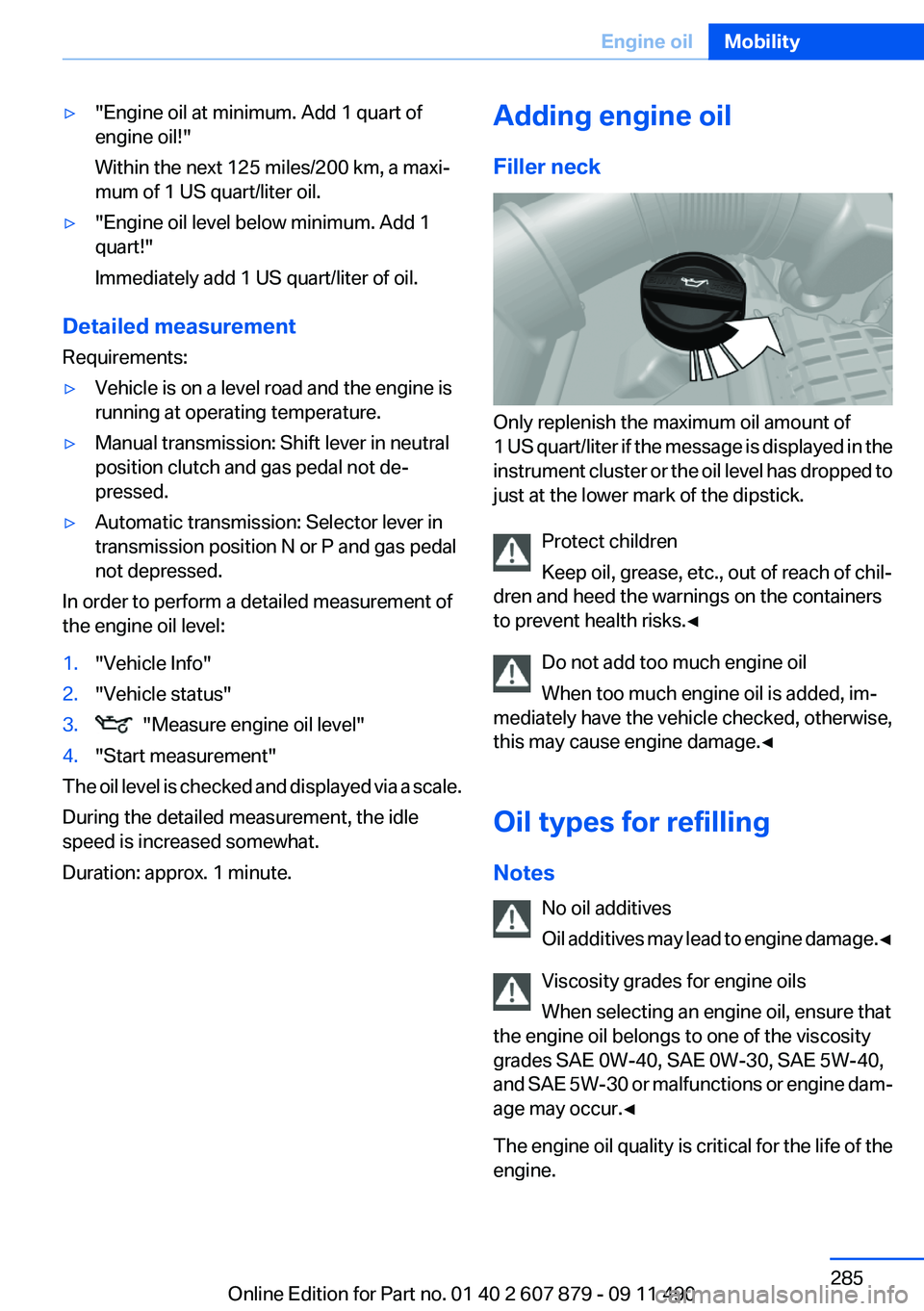
Filler neck
Only replenish the maximum oil amount of
1 US quart/liter if the message is displayed in the
instrument cluster or the oil level has dropped to
just at the lower mark of the dipstick.
Protect children
Keep oil, grease, etc., out of reach of chil‐
dren and heed the warnings on the containers
to prevent health risks.◀
Do not add too much engine oil
When too much engine oil is added, im‐
mediately have the vehicle checked, otherwise,
this may cause engine damage.◀
Oil types for refilling
Notes No oil additives
Oil additives may lead to engine damage. ◀
Viscosity grades for engine oils
When selecting an engine oil, ensure that
the engine oil belongs to one of the viscosity
grades SAE 0W-40, SAE 0W-30, SAE 5W-40,
and SAE 5W-30 or malfunctions or engine dam‐
age may occur.◀
The engine oil quality is critical for the life of the
engine.
Seite 285Engine oilMobility285
Online Edition for Part no. 01 40 2 607 879 - 09 11 490
Page 289 of 335
Socket for OBD Onboard
Diagnosis
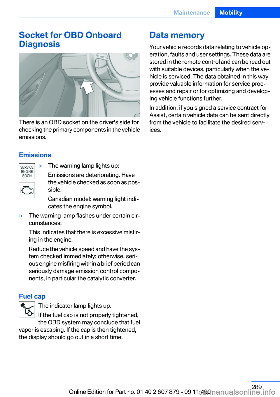
There is an OBD socket on the driver's side for
checking the primary components in the vehicle
emissions.
Emissions
▷The warning lamp lights up:
Emissions are deteriorating. Have
the vehicle checked as soon as pos‐
sible.
Canadian model: warning light indi‐
cates the engine symbol.▷The warning lamp flashes under certain cir‐
cumstances:
This indicates that there is excessive misfir‐
ing in the engine.
Reduce the vehicle speed and have the sys‐
tem checked immediately; otherwise, seri‐
ous engine misfiring within a brief period can
seriously damage emission control compo‐
nents, in particular the catalytic converter.
Fuel cap
The indicator lamp lights up.
If the fuel cap is not properly tightened,
the OBD system may conclude that fuel
vapor is escaping. If the cap is then tightened,
the display should go out in a short time.
Data memory
Your vehicle records data relating to vehicle op‐
eration, faults and user settings. These data are
stored in the remote control and can be read out
with suitable devices, particularly when the ve‐
hicle is serviced. The data obtained in this way
provide valuable information for service proc‐
esses and repair or for optimizing and develop‐
ing vehicle functions further.
In addition, if you signed a service contract for
Assist, certain vehicle data can be sent directly
from the vehicle to facilitate the desired serv‐
ices.Seite 289MaintenanceMobility289
Online Edition for Part no. 01 40 2 607 879 - 09 11 490