2012 BMW 335I SEDAN socket
[x] Cancel search: socketPage 145 of 325
The setting is stored automatically after approx‐
imately 10 seconds.
Ashtray/cigarette lighter
Ashtray
Opening
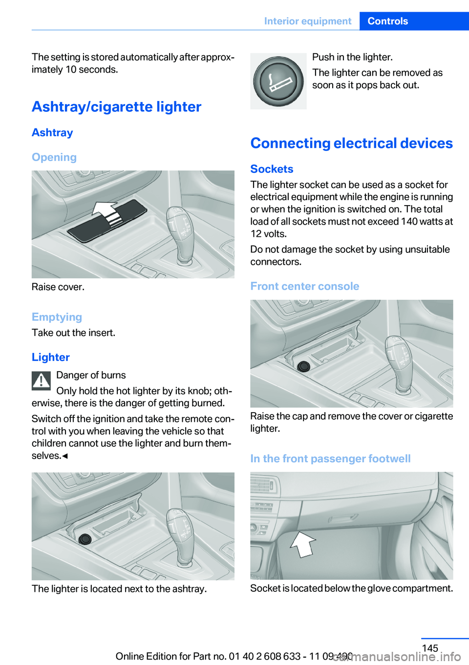
Raise cover.
Emptying
Take out the insert.
Lighter Danger of burns
Only hold the hot lighter by its knob; oth‐
erwise, there is the danger of getting burned.
Switch off the ignition and take the remote con‐
trol with you when leaving the vehicle so that
children cannot use the lighter and burn them‐
selves.◀
The lighter is located next to the ashtray.
Push in the lighter.
The lighter can be removed as
soon as it pops back out.
Connecting electrical devices
Sockets
The lighter socket can be used as a socket for
electrical equipment while the engine is running
or when the ignition is switched on. The total
load of all sockets must not exceed 140 watts at
12 volts.
Do not damage the socket by using unsuitable
connectors.
Front center console
Raise the cap and remove the cover or cigarette
lighter.
In the front passenger footwell
Socket is located below the glove compartment.
Seite 145Interior equipmentControls145
Online Edition for Part no. 01 40 2 608 633 - 11 09 490
Page 146 of 325
Rear center console
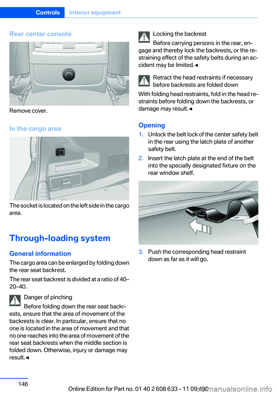
Remove cover.
In the cargo area
The socket is located on the left side in the cargo
area.
Through-loading system
General information
The cargo area can be enlarged by folding down
the rear seat backrest.
The rear seat backrest is divided at a ratio of 40–
20–40.
Danger of pinching
Before folding down the rear seat backr‐
ests, ensure that the area of movement of the
backrests is clear. In particular, ensure that no
one is located in the area of movement and that
no one reaches into the area of movement of the
rear seat backrests when the middle section is
folded down. Otherwise, injury or damage may
result.◀
Locking the backrest
Before carrying persons in the rear, en‐
gage and thereby lock the backrests, or the re‐
straining effect of the safety belts during an ac‐
cident may be limited.◀
Retract the head restraints if necessary
before backrests are folded down
With folding head restraints, fold in the head re‐
straints before folding down the backrests, or
damage may result.◀
Opening1.Unlock the belt lock of the center safety belt
in the rear using the latch plate of another
safety belt.2.Insert the latch plate at the end of the belt
into the specially designated fixture on the
rear window shelf.3.Push the corresponding head restraint
down as far as it will go.Seite 146ControlsInterior equipment146
Online Edition for Part no. 01 40 2 608 633 - 11 09 490
Page 213 of 325
Current playback
List of tracks currently being played.1."CD/Multimedia"2."External devices"3.Select the or symbol.4. "Current playback"
Random playback
The current list of tracks is played back in ran‐
dom order.
1."CD/Multimedia"2."External devices"3."Options" Open.4."Random"
Fast forward/reverse
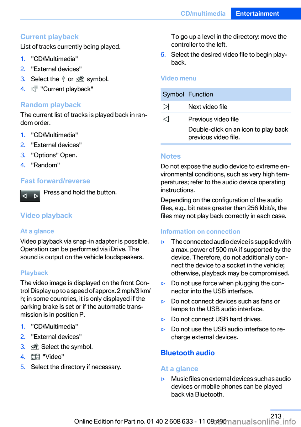
Press and hold the button.
Video playback
At a glance
Video playback via snap-in adapter is possible.
Operation can be performed via iDrive. The
sound is output on the vehicle loudspeakers.
Playback
The video image is displayed on the front Con‐
trol Display up to a speed of approx. 2 mph/3 km/
h; in some countries, it is only displayed if the
parking brake is set or if the automatic trans‐
mission is in position P.
1."CD/Multimedia"2."External devices"3. Select the symbol.4. "Video"5.Select the directory if necessary.To go up a level in the directory: move the
controller to the left.6.Select the desired video file to begin play‐
back.
Video menu
SymbolFunction Next video file Previous video file
Double-click on an icon to play back
previous video file.
Notes
Do not expose the audio device to extreme en‐
vironmental conditions, such as very high tem‐
peratures; refer to the audio device operating
instructions.
Depending on the configuration of the audio
files, e.g., bit rates greater than 256 kbit/s, the
files may not play back correctly in each case.
Information on connection
▷The connected audio device is supplied with
a max. power of 500 mA if supported by the
device. Therefore, do not additionally con‐
nect the device to a socket in the vehicle;
otherwise, playback may be compromised.▷Do not use force when plugging the con‐
nector into the USB interface.▷Do not connect devices such as fans or
lamps to the USB audio interface.▷Do not connect USB hard drives.▷Do not use the USB audio interface to re‐
charge external devices.
Bluetooth audio
At a glance
▷Music files on external devices such as audio
devices or mobile phones can be played
back via Bluetooth.Seite 213CD/multimediaEntertainment213
Online Edition for Part no. 01 40 2 608 633 - 11 09 490
Page 278 of 325
Socket for OBD Onboard
Diagnosis
Position
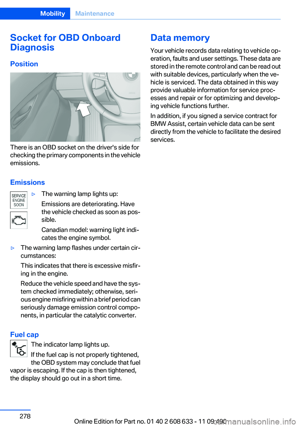
There is an OBD socket on the driver's side for
checking the primary components in the vehicle
emissions.
Emissions
▷The warning lamp lights up:
Emissions are deteriorating. Have
the vehicle checked as soon as pos‐
sible.
Canadian model: warning light indi‐
cates the engine symbol.▷The warning lamp flashes under certain cir‐
cumstances:
This indicates that there is excessive misfir‐
ing in the engine.
Reduce the vehicle speed and have the sys‐
tem checked immediately; otherwise, seri‐
ous engine misfiring within a brief period can
seriously damage emission control compo‐
nents, in particular the catalytic converter.
Fuel cap
The indicator lamp lights up.
If the fuel cap is not properly tightened,
the OBD system may conclude that fuel
vapor is escaping. If the cap is then tightened,
the display should go out in a short time.
Data memory
Your vehicle records data relating to vehicle op‐
eration, faults and user settings. These data are
stored in the remote control and can be read out
with suitable devices, particularly when the ve‐
hicle is serviced. The data obtained in this way
provide valuable information for service proc‐
esses and repair or for optimizing and develop‐
ing vehicle functions further.
In addition, if you signed a service contract for
BMW Assist, certain vehicle data can be sent
directly from the vehicle to facilitate the desired
services.Seite 278MobilityMaintenance278
Online Edition for Part no. 01 40 2 608 633 - 11 09 490
Page 281 of 325
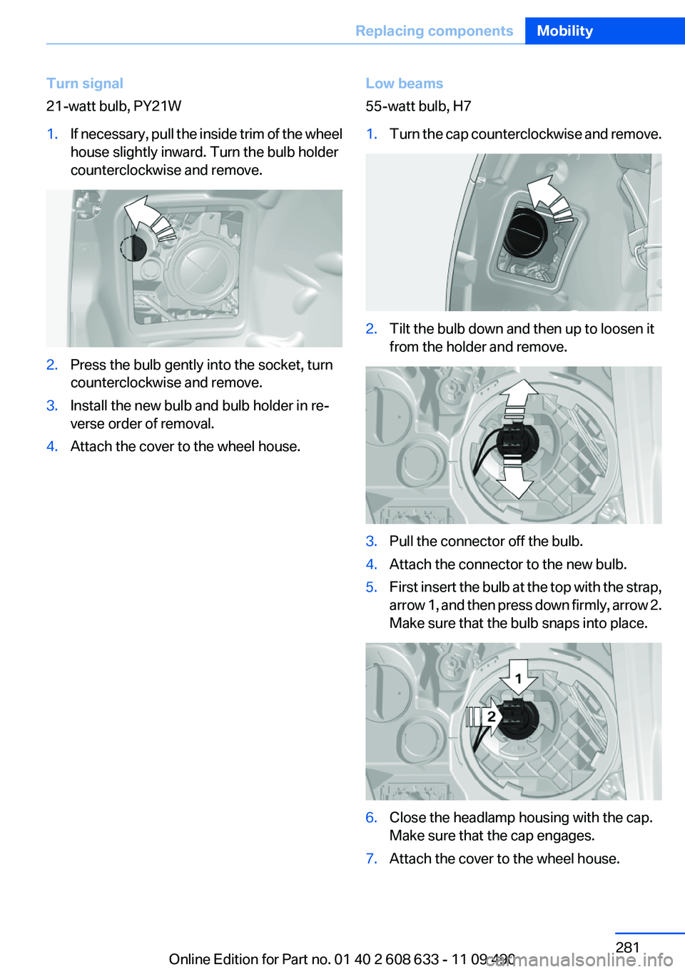
Turn signal
21-watt bulb, PY21W1.If necessary, pull the inside trim of the wheel
house slightly inward. Turn the bulb holder
counterclockwise and remove.2.Press the bulb gently into the socket, turn
counterclockwise and remove.3.Install the new bulb and bulb holder in re‐
verse order of removal.4.Attach the cover to the wheel house.Low beams
55-watt bulb, H71.Turn the cap counterclockwise and remove.2.Tilt the bulb down and then up to loosen it
from the holder and remove.3.Pull the connector off the bulb.4.Attach the connector to the new bulb.5.First insert the bulb at the top with the strap,
arrow 1, and then press down firmly, arrow 2.
Make sure that the bulb snaps into place.6.Close the headlamp housing with the cap.
Make sure that the cap engages.7.Attach the cover to the wheel house.Seite 281Replacing componentsMobility281
Online Edition for Part no. 01 40 2 608 633 - 11 09 490
Page 282 of 325
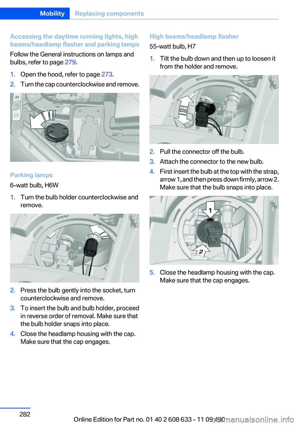
Accessing the daytime running lights, high
beams/headlamp flasher and parking lamps
Follow the General instructions on lamps and
bulbs, refer to page 279.1.Open the hood, refer to page 273.2.Turn the cap counterclockwise and remove.
Parking lamps
6-watt bulb, H6W
1.Turn the bulb holder counterclockwise and
remove.2.Press the bulb gently into the socket, turn
counterclockwise and remove.3.To insert the bulb and bulb holder, proceed
in reverse order of removal. Make sure that
the bulb holder snaps into place.4.Close the headlamp housing with the cap.
Make sure that the cap engages.High beams/headlamp flasher
55-watt bulb, H71.Tilt the bulb down and then up to loosen it
from the holder and remove.2.Pull the connector off the bulb.3.Attach the connector to the new bulb.4.First insert the bulb at the top with the strap,
arrow 1, and then press down firmly, arrow 2.
Make sure that the bulb snaps into place.5.Close the headlamp housing with the cap.
Make sure that the cap engages.Seite 282MobilityReplacing components282
Online Edition for Part no. 01 40 2 608 633 - 11 09 490
Page 284 of 325
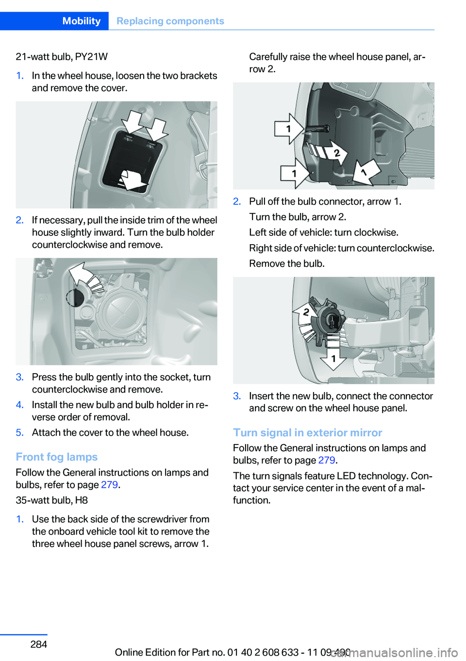
21-watt bulb, PY21W1.In the wheel house, loosen the two brackets
and remove the cover.2.If necessary, pull the inside trim of the wheel
house slightly inward. Turn the bulb holder
counterclockwise and remove.3.Press the bulb gently into the socket, turn
counterclockwise and remove.4.Install the new bulb and bulb holder in re‐
verse order of removal.5.Attach the cover to the wheel house.
Front fog lamps
Follow the General instructions on lamps and
bulbs, refer to page 279.
35-watt bulb, H8
1.Use the back side of the screwdriver from
the onboard vehicle tool kit to remove the
three wheel house panel screws, arrow 1.Carefully raise the wheel house panel, ar‐
row 2.2.Pull off the bulb connector, arrow 1.
Turn the bulb, arrow 2.
Left side of vehicle: turn clockwise.
Right side of vehicle: turn counterclockwise.
Remove the bulb.3.Insert the new bulb, connect the connector
and screw on the wheel house panel.
Turn signal in exterior mirror
Follow the General instructions on lamps and
bulbs, refer to page 279.
The turn signals feature LED technology. Con‐
tact your service center in the event of a mal‐
function.
Seite 284MobilityReplacing components284
Online Edition for Part no. 01 40 2 608 633 - 11 09 490
Page 286 of 325
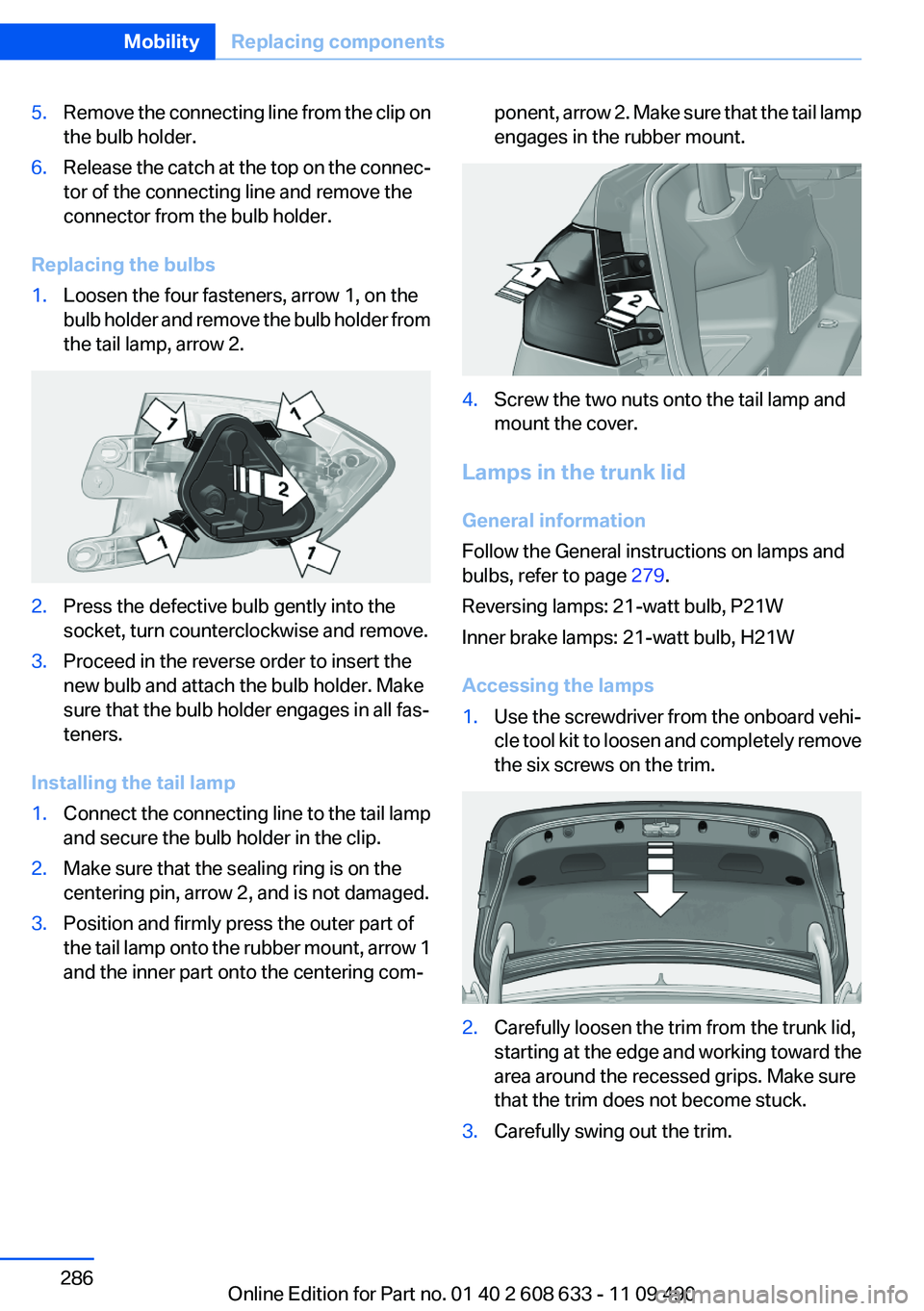
5.Remove the connecting line from the clip on
the bulb holder.6.Release the catch at the top on the connec‐
tor of the connecting line and remove the
connector from the bulb holder.
Replacing the bulbs
1.Loosen the four fasteners, arrow 1, on the
bulb holder and remove the bulb holder from
the tail lamp, arrow 2.2.Press the defective bulb gently into the
socket, turn counterclockwise and remove.3.Proceed in the reverse order to insert the
new bulb and attach the bulb holder. Make
sure that the bulb holder engages in all fas‐
teners.
Installing the tail lamp
1.Connect the connecting line to the tail lamp
and secure the bulb holder in the clip.2.Make sure that the sealing ring is on the
centering pin, arrow 2, and is not damaged.3.Position and firmly press the outer part of
the tail lamp onto the rubber mount, arrow 1
and the inner part onto the centering com‐ponent, arrow 2. Make sure that the tail lamp
engages in the rubber mount.4.Screw the two nuts onto the tail lamp and
mount the cover.
Lamps in the trunk lid
General information
Follow the General instructions on lamps and
bulbs, refer to page 279.
Reversing lamps: 21-watt bulb, P21W
Inner brake lamps: 21-watt bulb, H21W
Accessing the lamps
1.Use the screwdriver from the onboard vehi‐
cle tool kit to loosen and completely remove
the six screws on the trim.2.Carefully loosen the trim from the trunk lid,
starting at the edge and working toward the
area around the recessed grips. Make sure
that the trim does not become stuck.3.Carefully swing out the trim.Seite 286MobilityReplacing components286
Online Edition for Part no. 01 40 2 608 633 - 11 09 490