2012 BMW 335I ECU
[x] Cancel search: ECUPage 67 of 325

Otherwise, there is the danger of fire and a risk
to personal safety if the fluid is spilled.◀
All washer nozzles are supplied from one reser‐
voir.
Fill with water and – if required – with a washer
antifreeze, according to the manufacturer's rec‐
ommendations.
Mix the washer fluid before adding to maintain
the correct mixing ratio.
Manual transmission
Shifting Shifting into 5th or 6th gear
When shifting into 5th or 6th gear, push
the gearshift lever to the right; otherwise inad‐
vertent shifting into the 3rd or 4th gear could
lead to engine damage.◀
Reverse gear
Select only when the vehicle is stationary. When
the gearshift lever is pressed to the left, a slight
resistance needs to be overcome.
Automatic transmission with
Steptronic
Transmission positions
D Drive, automatic position
Position for normal vehicle operation. All for‐
ward gears are available.
R is Reverse
Select only when the vehicle is stationary.
N is Neutral
Use in automatic car washes, for example. The
vehicle can roll.
When the ignition is switched off, refer to
page 59, position P is engaged automatically.
P Park
Select only when the vehicle is stationary. The
drive wheels are blocked.
P is engaged automatically:▷After the engine is switched off, if the car is
in radio ready state, refer to page 60, or if the
ignition is switched off, refer to page 59, and
if position R or D is engaged.▷With the ignition is off, if position N is en‐
gaged.▷If the safety belt is unbuckled, the driver's
door is opened, and the brake pedal is not
pressed while the vehicle is stationary and
transmission position R or D is engaged.
Before exiting the vehicle, make sure that posi‐
tion P of the automatic transmission is engaged.
Otherwise, the vehicle may begin to roll.
Kickdown
Kickdown is used to achieve maximum driving
performance. Press on the gas pedal beyond the
resistance point at the full throttle position.
Engaging the transmission position
▷Transmission position P can only be disen‐
gaged if the engine is running and the brake
pedal is pressed.▷With the vehicle stationary, press on the
brake pedal before shifting out of P or N;
otherwise, the shift command will not be
executed: shift lock.Seite 67DrivingControls67
Online Edition for Part no. 01 40 2 608 633 - 11 09 490
Page 75 of 325

Supplementary text messages
Addition information, such as on the cause of a
fault or the required action, can be called up via
Check Control.
The supplementary text of urgent messages is
displayed on the Control Display automatically.
Symbols
Depending on the Check Control message, the
following functions can be selected.▷ "Owner's Manual"
Display additional information about the
Check Control message in the integrated
owner's manual.▷ "Service request"
Contact the service partner.▷ "Roadside Assistance"
Contact Roadside Assistance.
Hiding Check Control messages
Press the computer button on the turn signal
lever.
▷Some Check Control messages are dis‐
played continuously and are not cleared un‐
til the malfunction is eliminated. If several
malfunctions occur at once, the messages
are displayed consecutively.
These messages can be hidden for approx.
8 seconds. After this time, they are dis‐
played again automatically.▷Other Check Control messages are hidden
automatically after approx. 20 seconds.They are stored and can be displayed again
later.
Displaying stored Check Control
messages
1."Vehicle Info"2."Vehicle status"3. "Check Control"4.Select the text message.
Messages after trip completion
Special messages that are displayed during
driving are displayed again after the ignition is
switched off.
Fuel gauge The vehicle inclination may
cause the display to vary.
Notes on refueling, refer to
page 260.
Tachometer Always avoid engine speeds in
the red warning field. In this
range, the fuel supply is inter‐
rupted to protect the engine.
Engine oil temperature
▷Cold engine: the pointer is at
the low temperature end.
Drive at moderate engine and
vehicle speeds.▷Normal operating tempera‐
ture: the pointer is in the mid‐
dle or in the left half of the
temperature display.Seite 75DisplaysControls75
Online Edition for Part no. 01 40 2 608 633 - 11 09 490
Page 103 of 325

ahead or stopped in front of you can also be de‐
tected within the system's range.
Personal responsibility
The system cannot serve as a substitute
for the driver's personal judgment of the traffic
situation. The system may not always detect
critical situations reliably and in a timely manner.
Adapt speed to traffic situation and drive alertly;
otherwise, a risk to safety may result.◀
Function
After the safety belt is buckled, the front belts
are automatically tightened once after the vehi‐
cle is driven is away.
In critical driving situations, the following indi‐
vidual functions become active:▷The front belts are automatically tightened.▷Automatic closing of the windows.▷Automatic closing of the glass sunroof.
After a critical driving situation without an acci‐
dent, the front belts are loosened again. All other
systems can be restored to the desired setting.
If the belt tension does not loosen automatically,
stop the vehicle and unbuckle the belt using the
red button in the buckle. Fasten the belt before
continuing on your trip.
PostCrash
In the event of an accident, the system can bring
the car to a halt automatically without interven‐
tion by the driver in certain situations. This can
reduce the risk of a further collision.
Depressing the brake pedal can cause the vehi‐
cle to brake harder. This interrupts automatic
braking. Depressing the accelerator pedal also
interrupts automatic braking.
After coming to a halt, the brake is released au‐
tomatically. Secure the vehicle against rolling.
Seite 103SafetyControls103
Online Edition for Part no. 01 40 2 608 633 - 11 09 490
Page 111 of 325

▷Each time the rocker switch is pressed past
the point of resistance, the desired speed
increases or decreases by a maximum of
5 mph/10 km/h. Max. adjustable speed:
110 mph/180 km/h.
Hold the rocker switch in position to repeat the
action.
Distance Selecting a distance
Adjust the distance according to the traffic
and weather conditions; otherwise, there is the
danger of an accident occurring. Maintain the
prescribed safety distance.◀
Reduce distance Press the button repeatedly until the
desired distance is set.
The selected distance, refer to page 112, is dis‐
played in the instrument cluster.
Increase distance Press the button repeatedly until the
desired distance is set.
The selected distance, refer to page 112, is dis‐
played in the instrument cluster.
Calling up the desired speed and
distance
While driving Press the button with the system
switched on.
In the following cases, the stored speed value is
deleted and cannot be called up again:
▷When the system is switched off.▷When the ignition is switched off.While standing
Before leaving the vehicle, secure it
against rolling.
Before leaving the vehicle with the engine run‐
ning, engage position P of the automatic trans‐
mission and apply the parking brake. Otherwise,
the vehicle may begin to roll.◀
The system brought the vehicle to a complete
standstill.▷Green mark in the speedometer during a
brief idle phase:
The vehicle ahead of you drives away while
the mark is green: your vehicle accelerates
without anything having to be done.▷Switch to orange of the mark in the speed‐
ometer after approx. 2 sec.:
The vehicle ahead of you drives away, while
the mark is orange: in order to accelerate,
briefly press the gas pedal or press the RES
button or SET button.
Rolling bars in the distance indicator mean that
the vehicle ahead of you has driven off.
You actively braked your vehicle to a halt by
pressing on the brake pedal and it is standing
behind another vehicle:
1. Press the button to call up a stored
desired speed.2.Release the brake pedal.3.Press on the accelerator briefly, or press the
RES button or the rocker switch when the
vehicle ahead of you drives away.
Displays in the instrument cluster
Desired speed
▷The marking lights up in
green: the system is active.▷The marking lights up in or‐
ange: the system has been
interrupted.Seite 111Driving comfortControls111
Online Edition for Part no. 01 40 2 608 633 - 11 09 490
Page 117 of 325

Camera
The camera is located near the base of the mir‐
ror.
Keep windshield clean and clear in the area in
front of the interior rear view mirror.
Collision warning with
braking function
The concept
If the vehicle is equipped with Active Cruise
Control with Stop & Go, the collision warning is
controlled via the cruise control radar sensor.
The system issues a two-phase warning of a
danger of collision at speeds above approx.
10 mph/15 km/h. The time of these warnings
may vary depending on the current driving sit‐
uation.
The collision warning is available even if cruise
control has been deactivated.
It responds to stationary or moving objects that
are within the detection range of the radar sys‐
tem.
When the vehicle is intentionally brought into
contact with a vehicle, the collision warning is
delayed to avoid false warnings.
Warning stages
Prewarning
This warning is issued, for example, when there
is the impending danger of a collision or the dis‐
tance to the vehicle ahead is too small.
Acute warning with braking function
Warning of the imminent danger of a collision
when the vehicle approaches another object at
a relatively high differential speed.
The acute warning prompts the driver to inter‐
vene and, if there is the danger of a collision, is
accompanied by a braking intervention.
The braking intervention is executed with lim‐
ited braking force and for a brief period only. The
intervention cannot bring the vehicle to a com‐
plete standstill.
The braking intervention is executed only if DSC
Dynamic Stability Control is switched on.
Adapting your speed and driving style
The acute warning does not relieve the
driver of the responsibility to adapt his or her
driving speed and style to the traffic condi‐
tions.◀
The braking intervention can be interrupted by
pressing on the accelerator or by actively mov‐
ing the steering wheel.
When towing or tow-starting the vehicle, switch
off the collision warning with braking function to
prevent undesired interventions.
The braking function is deactivated if the DSC
Dynamic Stability Control or DTC Dynamic
Traction Control is deactivated.Seite 117Driving comfortControls117
Online Edition for Part no. 01 40 2 608 633 - 11 09 490
Page 141 of 325

Interior equipmentVehicle equipment
All standard, country-specific and optional
equipment that is offered in the model series is
described in this chapter. Therefore, equipment
is also described that is not available in a vehicle,
e. g., because of the selected optional equip‐
ment or country variant. This also applies for
safety-related functions and systems.
Integrated universal remote
control
The concept
The integrated universal remote control can op‐
erate up to 3 functions of remote-controlled sys‐
tems such as garage door drives or lighting sys‐
tems. The integrated universal remote control
replaces up to 3 different hand-held transmit‐
ters. To operate the remote control, the buttons
on the interior rearview mirror must be program‐
med with the desired functions. The hand-held
transmitter for the particular system is required
in order to program the remote control.
During programming
During programming and before activat‐
ing a device using the integrated universal re‐
mote control, ensure that there are no people,
animals, or objects in the range of movement of
the remote-controlled device; otherwise, there
is a risk of injury or damage.
Also follow the safety instructions of the hand-
held transmitter.◀
Before selling the vehicle, delete the stored
functions for the sake of security.
Compatibility If this symbol is printed on the packaging
or in the instructions of the system to be
controlled, the system is generally com‐patible with the integrated universal remote
control.
If you have any questions, please contact:▷Your service center.▷www.homelink.com on the Internet.
HomeLink is a registered trademark of Johnson
Controls, Inc.
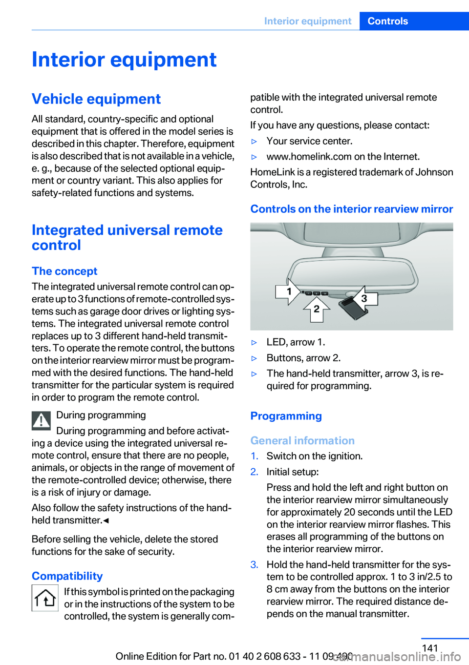
Controls on the interior rearview mirror
▷LED, arrow 1.▷Buttons, arrow 2.▷The hand-held transmitter, arrow 3, is re‐
quired for programming.
Programming
General information
1.Switch on the ignition.2.Initial setup:
Press and hold the left and right button on
the interior rearview mirror simultaneously
for approximately 20 seconds until the LED
on the interior rearview mirror flashes. This
erases all programming of the buttons on
the interior rearview mirror.3.Hold the hand-held transmitter for the sys‐
tem to be controlled approx. 1 to 3 in/2.5 to
8 cm away from the buttons on the interior
rearview mirror. The required distance de‐
pends on the manual transmitter.Seite 141Interior equipmentControls141
Online Edition for Part no. 01 40 2 608 633 - 11 09 490
Page 147 of 325

4.Pull the corresponding lever in the cargo
area to release the rear seat backrest.5.The unlocked rear seat backrest moves for‐
ward slightly. Fold the backrest forward by
the head restraint.
Closing
1.Return the rear seat backrest to the upright
seating position and engage it.
Ensure that the lock is securely en‐
gaged
When folding back the backrest, be sure that
it locks in place securely. If it is not properly
engaged, transported cargo could enter the
passenger compartment during braking or
evasive maneuvers and endanger the vehi‐
cle occupants.◀2.Release the latch plate from the fixture on
the rear window shelf and insert it into the
belt lock of the center safety belt. Make sure
you hear the latch plate engage.
To secure cargo, refer to page 160, with nets or
draw straps, the cargo area is fitted with lashing
eyes.
Folding down the middle section1.Fold in the middle head restraint.2.Reach into the recess and pull the middle
section forward.Seite 147Interior equipmentControls147
Online Edition for Part no. 01 40 2 608 633 - 11 09 490
Page 148 of 325

Storage compartmentsVehicle equipment
All standard, country-specific and optional
equipment that is offered in the model series is
described in this chapter. Therefore, equipment
is also described that is not available in a vehicle,
e. g., because of the selected optional equip‐
ment or country variant. This also applies for
safety-related functions and systems.
Notes No loose objects in the passenger com‐
partment
Do not stow any objects in the passenger com‐
partment without securing them; otherwise,
they may present a danger to occupants for in‐
stance during braking and avoidance maneu‐
vers.◀
Do not place anti-slip mats on the dash‐
board
Do not place anti-slip mats on the dashboard.
The mat materials could damage the dash‐
board.◀
Storage compartments
The following storage compartments are avail‐
able in the vehicle interior:▷Glove compartment on the front passenger
side, refer to page 148.▷Without Smoker's package: Front storage
compartment, in front of the cupholders, re‐
fer to page 149.▷Storage compartment in the front center
armrest, refer to page 149.▷Compartments in the doors, refer to
page 149.▷Nets on the backrests of the front seats.▷Storage compartment in the rear center
console, refer to page 150.
Glove compartment
Front passenger side
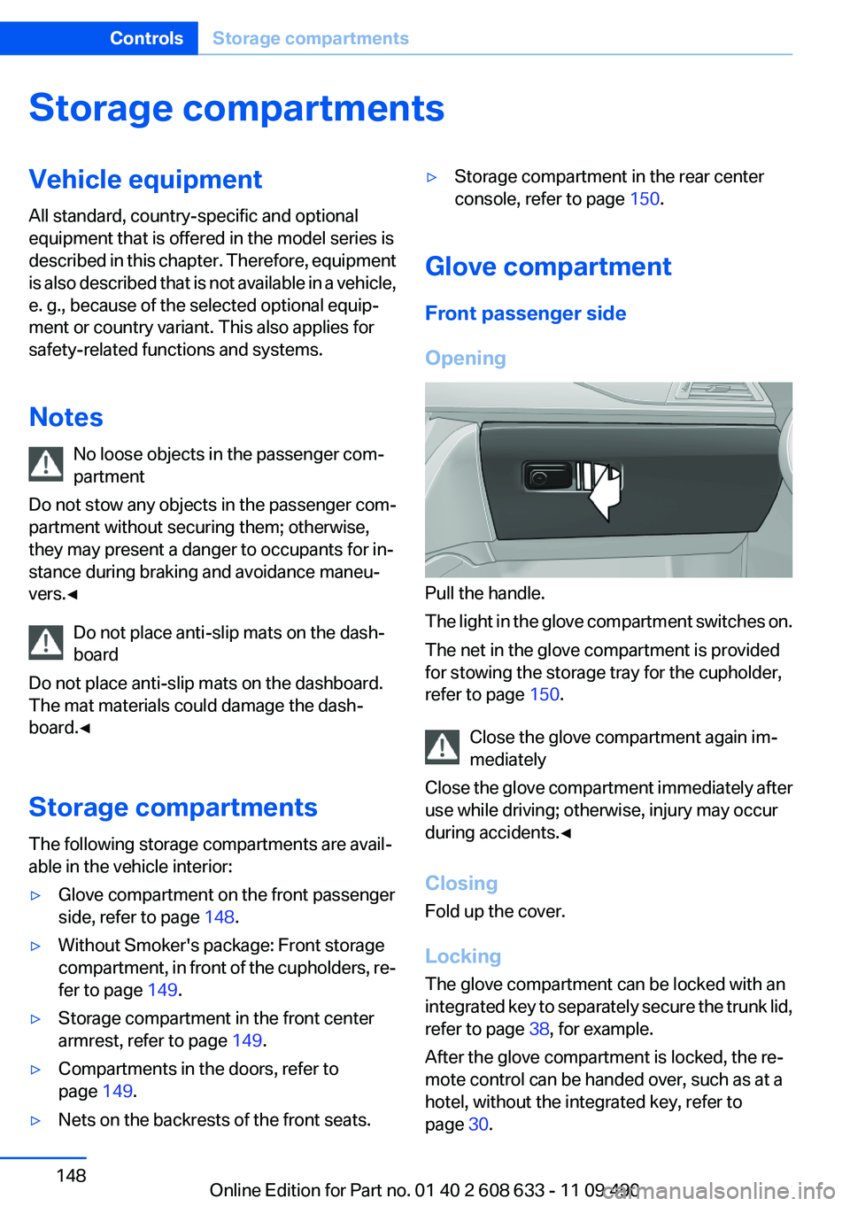
Opening
Pull the handle.
The light in the glove compartment switches on.
The net in the glove compartment is provided
for stowing the storage tray for the cupholder,
refer to page 150.
Close the glove compartment again im‐
mediately
Close the glove compartment immediately after
use while driving; otherwise, injury may occur
during accidents.◀
Closing
Fold up the cover.
Locking
The glove compartment can be locked with an
integrated key to separately secure the trunk lid,
refer to page 38, for example.
After the glove compartment is locked, the re‐
mote control can be handed over, such as at a
hotel, without the integrated key, refer to
page 30.
Seite 148ControlsStorage compartments148
Online Edition for Part no. 01 40 2 608 633 - 11 09 490