2012.5 Peugeot 308 SW BL cooling
[x] Cancel search: coolingPage 32 of 382
1
30
INSTRUMENTS and CONTROLS
Warning lamp
is on
Cause
Action / Observations
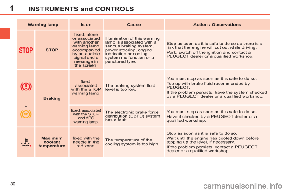
STOP
fi xed, alone
or associated
with another
warning lamp,
accompanied
by an audible
signal and a
message in
the screen. Illumination of this warning
lamp is associated with a
serious braking system,
power steering, engine
lubrication or cooling
system malfunction or a
punctured tyre. Stop as soon as it is safe to do so as there is a
risk that the engine will cut out while driving.
Park, switch off the ignition and contact a
PEUGEOT dealer or a qualifi ed workshop.
Braking
fi xed,
associated
with the STOP
warning lamp. The braking system fl uid
level is too low. You must stop as soon as it is safe to do so.
Top up with brake fl uid recommended by
PEUGEOT.
If the problem persists, have the system checked
by a PEUGEOT dealer or a qualifi ed workshop.
+
fi xed, associated
with the STOP
and ABS
warning lamp.
The electronic brake force
distribution (EBFD) system
has a fault. You must stop as soon as it is safe to do so.
Have it checked by a PEUGEOT dealer or a
qualifi ed workshop.
Maximum
coolant
temperature
fi xed with the
needle in the
red zone. The temperature of the
cooling system is too high. Stop as soon as it is safe to do so.
Wait until the engine has cooled down before
topping up the level, if necessary.
If the problem persists, contact a PEUGEOT
dealer or a qualifi ed workshop.
Page 41 of 382
1
39
INSTRUMENTS and CONTROLS
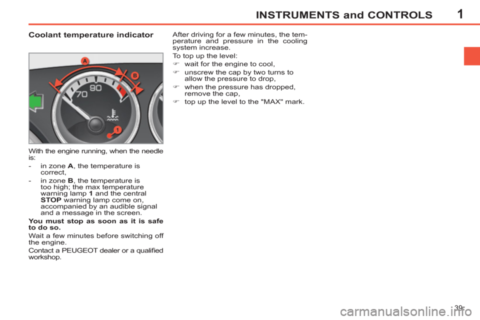
Coolant temperature indicator
With the engine running, when the needle
is:
- in zone A
, the temperature is
correct,
- in zone B
, the temperature is
too high; the max temperature
warning lamp 1
and the central
STOP
warning lamp come on,
accompanied by an audible signal
and a message in the screen.
You must stop as soon as it is safe
to do so.
Wait a few minutes before switching off
the engine.
Contact a PEUGEOT dealer or a qualifi ed
workshop. After driving for a few minutes, the tem-
perature and pressure in the cooling
system increase.
To top up the level:
�)
wait for the engine to cool,
�)
unscrew the cap by two turns to
allow the pressure to drop,
�)
when the pressure has dropped,
remove the cap,
�)
top up the level to the "MAX" mark.
Page 63 of 382
3
61
COMFORT
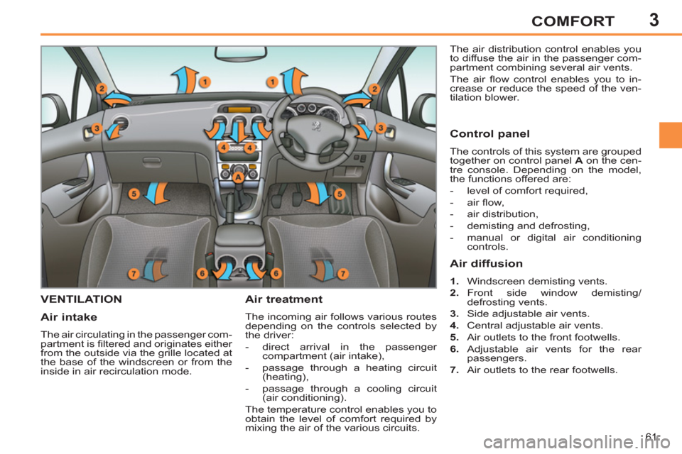
VENTILATION
Air treatment
The incoming air follows various routes
depending on the controls selected by
the driver:
- direct arrival in the passenger
compartment (air intake),
- passage through a heating circuit
(heating),
- passage through a cooling circuit
(air conditioning).
The temperature control enables you to
obtain the level of comfort required by
mixing the air of the various circuits. The air distribution control enables you
to diffuse the air in the passenger com-
partment combining several air vents.
The air fl ow control enables you to in-
crease or reduce the speed of the ven-
tilation blower.
Air intake
The air circulating in the passenger com-
partment is fi ltered and originates either
from the outside via the grille located at
the base of the windscreen or from the
inside in air recirculation mode.
Control panel
The controls of this system are grouped
together on control panel A
on the cen-
tre console. Depending on the model,
the functions offered are:
- level of comfort required,
- air fl ow,
- air distribution,
- demisting and defrosting,
- manual or digital air conditioning
controls.
Air diffusion
1.
Windscreen demisting vents.
2.
Front side window demisting/
defrosting vents.
3.
Side adjustable air vents.
4.
Central adjustable air vents.
5.
Air outlets to the front footwells.
6.
Adjustable air vents for the rear
passengers.
7.
Air outlets to the rear footwells.
Page 69 of 382
3
67
COMFORT
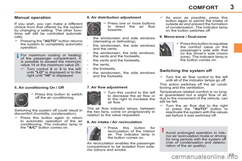
Manual operation
If you wish, you can make a different
choice from that offered by the system
by changing a setting. The other func-
tions will still be controlled automati-
cally.
�)
Pressing the "AUTO"
button returns
the system to completely automatic
operation.
�)
Press this button to switch
off the air conditioning.
6. Air distribution adjustment
�)
Press one or more buttons
to direct the air fl ow
towards:
7. Air fl ow adjustment
�)
Turn this control to the left
to decrease the air fl ow or
to the right to increase the
air fl ow.
8. Air intake / Air recirculation
Switching the system off
�)
Turn the air fl ow control to the left
until all of the indicator lamps go off.
This action switches off the air condi-
tioning and the ventilation.
Temperature related comfort is no long-
er guaranteed but a slight fl ow of air,
due to the movement of the vehicle, can
still be felt.
�)
Turn the air fl ow dial to the right
or press the "AUTO"
button to
reactivate the system with the values
set before it was switched off.
�)
Press this button for
recirculation of the interior
air. The indicator lamp in
the button comes on.
5. Air conditioning On / Off
Avoid prolonged operation in inte-
rior air recirculation mode or driving
for long periods with the system off
(risk of condensation and deterio-
ration of the air quality).
- the windscreen and side windows
(demisting or defrosting),
- the windscreen, the side windows
and the vents,
- the windscreen, the side windows,
the vents and the footwells,
- the vents and the footwells,
- the vents,
- the footwells,
- the windscreen, the side windows
and the footwells.
The air fl ow indicator lamps, between
the two fans, come on progressively in
relation to the value requested.
�)
As soon as possible, press this
button again to permit the intake of
outside air and prevent the formation
of condensation. The indicator lamp
on the button switches off.
For maximum cooling or heating
of the passenger compartment, it
is possible to exceed the minimum
value 14 or the maximum value 28.
�)
Turn control 2
or 3
to the left
until "LO"
is displayed or to the
right until "HI"
is displayed.
9. Mono-zone / Dual-zone
�)
Press this button to equalise
the comfort value on the
passenger's side with that
on the driver's side (mono
zone). The indicator lamp in
the button comes on.
Air recirculation enables the passenger
compartment to be isolated from exte-
rior odours and smoke.
Switching the system off could result in
discomfort (humidity, condensation).
�)
Press this button again to return
to automatic operation of the air
conditioning. The indicator lamp in
the "A/C"
button comes on.
Page 176 of 382
10
174
CHECKS
CHECKING LEVELS
Check all of these levels regularly and
top them up if necessary, unless other-
wise indicated.
If a level drops signifi cantly, have the
corresponding system checked by a
PEUGEOT dealer or a qualifi ed work-
shop.
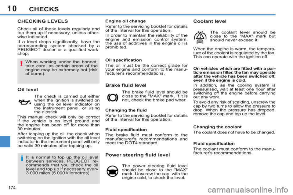
Brake fluid level
On vehicles which are fi tted with a par-
ticle emission fi lter, the fan may operate
after the vehicle has been switched off,
even if the engine is cold.
In addition, as the cooling system is
pressurised, wait at least one hour after
switching off the engine before carrying
out any work.
To avoid any risk of scalding, unscrew the
cap by two turns to allow the pressure to
drop. When the pressure has dropped,
remove the cap and top up the level.
Oil level
The check is carried out either
when the ignition is switched on
using the oil level indicator on
the instrument panel, or using
the dipstick.
This manual check will only be correct
if the vehicle is on level ground and
the engine has been off for more than
30 minutes.
After topping up the oil, the check when
switching on the ignition with the oil level
indicator in the instrument panel will only
be valid 30 minutes after topping up. The brake fl uid level should be
close to the "MAX" mark. If it is
not, check the brake pad wear.
Changing the fl uid
Refer to the servicing booklet for details
of the interval for this operation.
Power steering fluid level
The power steering fl uid level
should be close to the "MAX"
mark. Unscrew the cap, with the
engine cold, to check the level.
Engine oil change
Refer to the servicing booklet for details
of the interval for this operation.
In order to maintain the reliability of the
engine and emission control system,
the use of additives in the engine oil is
prohibited.
It is normal to top up the oil level
between services. PEUGEOT re-
commends that you check the oil
level and top up if necessary every
3 000 miles (5 000 kilometres).
Fluid specifi cation
The brake fl uid must conform to the
manufacturer's recommendations and
meet the DOT4 standard.
Changing the coolant
The coolant does not have to be changed.
Coolant level
The coolant level should be
close to the "MAX" mark but
should never exceed it.
When the engine is warm, the tempera-
ture of the coolant is regulated by the fan.
This can operate with the ignition off.
Fluid specifi cation
The coolant must conform to the manu-
facturer's recommendations.
When working under the bonnet,
take care, as certain areas of the
engine may be extremely hot (risk
of burns).
Oil specifi cation
The oil must be the correct grade for
your engine and conform to the manu-
facturer's recommendations.
Page 207 of 382
11
205
PRACTICAL INFORMATION
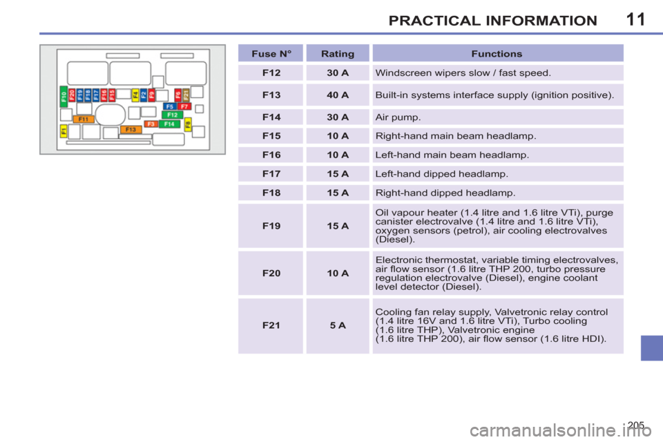
Fuse N°
Rating
Functions
F12
30 A
Windscreen wipers slow / fast speed.
F13
40 A
Built-in systems interface supply (ignition positive).
F14
30 A
Air pump.
F15
10 A
Right-hand main beam headlamp.
F16
10 A
Left-hand main beam headlamp.
F17
15 A
Left-hand dipped headlamp.
F18
15 A
Right-hand dipped headlamp.
F19
15 A
Oil vapour heater (1.4 litre and 1.6 litre VTi), purge
canister electrovalve (1.4 litre and 1.6 litre VTi),
oxygen sensors (petrol), air cooling electrovalves
(Diesel).
F20
10 A
Electronic thermostat, variable timing electrovalves,
air fl ow sensor (1.6 litre THP 200, turbo pressure
regulation electrovalve (Diesel), engine coolant
level detector (Diesel).
F21
5 A
Cooling fan relay supply, Valvetronic relay control
(1.4 litre 16V and 1.6 litre VTi), Turbo cooling
(1.6 litre THP), Valvetronic engine
(1.6 litre THP 200), air fl ow sensor (1.6 litre HDI).
Page 216 of 382
11
214
PRACTICAL INFORMATION
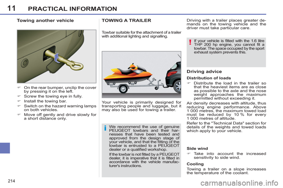
�)
On the rear bumper, unclip the cover
by pressing it on the left.
�)
Screw the towing eye in fully.
�)
Install the towing bar.
�)
Switch on the hazard warning lamps
on both vehicles.
�)
Move off gently and drive slowly for
a short distance only.
Towing another vehicle TOWING A TRAILER
Your vehicle is primarily designed for
transporting people and luggage, but it
may also be used for towing a trailer.
Driving advice
Side wind
�)
Take into account the increased
sensitivity to side wind.
Cooling
Towing a trailer on a slope increases
the temperature of the coolant.
Towbar suitable for the attachment of a trailer
with additional lighting and signalling.
Distribution of loads
�)
Distribute the load in the trailer so
that the heaviest items are as close
as possible to the axle and the nose
weight approaches the maximum
permitted without exceeding it.
Air density decreases with altitude, thus
reducing engine performance. Above
1 000 metres, the maximum towed load
must be reduced by 10 % for every
1 000 metres of altitude.
Refer to the "Technical Data" section for
details of the weights and towed loads
which apply to your vehicle. Driving with a trailer places greater de-
mands on the towing vehicle and the
driver must take particular care.
We recommend the use of genuine
PEUGEOT towbars and their har-
nesses that have been tested and
approved from the design stage of
your vehicle, and that the fi tting of the
towbar is entrusted to a PEUGEOT
dealer or a qualifi ed workshop.
If the towbar is not fi tted by a PEUGEOT
dealer, it is imperative that it is fi tted in
accordance with the vehicle manufac-
turer's instructions.
If your vehicle is fi tted with the 1.6 litre
THP 200 hp engine, you cannot fi t a
towbar. The space occupied by the sport
exhaust system prevents this.
Page 217 of 382
11
215
PRACTICAL INFORMATION
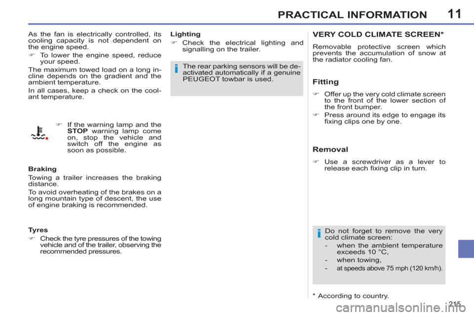
VERY COLD CLIMATE SCREEN *
Removable protective screen which
prevents the accumulation of snow at
the radiator cooling fan.
Fitting
�)
Offer up the very cold climate screen
to the front of the lower section of
the front bumper.
�)
Press around its edge to engage its
fi xing clips one by one.
Do not forget to remove the very
cold climate screen:
- when the ambient temperature
exceeds 10 °C,
- when towing,
-
at speeds above 75 mph (120 km/h).
Removal
�)
Use a screwdriver as a lever to
release each fi xing clip in turn. As the fan is electrically controlled, its
cooling capacity is not dependent on
the engine speed.
�)
To lower the engine speed, reduce
your speed.
The maximum towed load on a long in-
cline depends on the gradient and the
ambient temperature.
In all cases, keep a check on the cool-
ant temperature.
Braking
Towing a trailer increases the braking
distance.
To avoid overheating of the brakes on a
long mountain type of descent, the use
of engine braking is recommended.
Tyres
�)
Check the tyre pressures of the towing
vehicle and of the trailer, observing the
recommended pressures.
Lighting
�)
Check the electrical lighting and
signalling on the trailer.
The rear parking sensors will be de-
activated automatically if a genuine
PEUGEOT towbar is used.
�)
If the warning lamp and the
STOP
warning lamp come
on, stop the vehicle and
switch off the engine as
soon as possible.
*
According to country.