2011 YAMAHA YZ85 seat adjustment
[x] Cancel search: seat adjustmentPage 9 of 86

TABLE OF CONTENTS
LOCATION OF IMPORTANT
LABELS ............................................1-1
SAFETY INFORMATION .................. 2-1
DESCRIPTION .................................. 3-1
Left view .......................................... 3-1
Right view ........................................ 3-2
Controls and instruments ................3-3
INSTRUMENT AND CONTROL
FUNCTIONS....................................... 4-1
Handlebar switch ............................ 4-1
Clutch lever .................................... 4-1
Shift pedal ......................................4-1
Brake lever ..................................... 4-2
Brake pedal .................................... 4-2
Fuel tank cap .................................. 4-3
Fuel ................................................ 4-3
Fuel tank breather hose ................. 4-5
Fuel cock ........................................ 4-5
Starter (choke) knob ....................... 4-6
Kickstarter ......................................4-6
Seat ................................................ 4-7
Adjusting the front fork ................... 4-7
Front fork bleeding ......................... 4-9
Adjusting the shock absorber
assembly ..................................... 4-9
Removable sidestand ................... 4-12FOR YOUR SAFETY –
PRE-OPERATION CHECKS............. 5-1
OPERATION AND IMPORTANT
RIDING POINTS................................ 6-1
Starting and warming up a cold
engine ......................................... 6-1
Starting a warm engine .................. 6-1
Shifting ........................................... 6-2
Engine break-in .............................. 6-3
Parking ........................................... 6-4
PERIODIC MAINTENANCE AND
ADJUSTMENT................................... 7-1
Periodic maintenance and
lubrication chart .......................... 7-2
Checking the spark plug ................ 7-8
Transmission oil ............................. 7-9
Coolant ........................................ 7-10
Cleaning the air filter element ...... 7-12
Adjusting the carburetor ............... 7-14
Adjusting the engine idling
speed ........................................ 7-14
Adjusting the throttle grip free
play ........................................... 7-15
Tires ............................................. 7-15
Spoke wheels .............................. 7-17
Adjusting the clutch lever free
play ........................................... 7-17
Checking the brake lever free
play ........................................... 7-18Checking the shift pedal ............... 7-19
Checking the front and rear brake
pads .......................................... 7-19
Checking the brake fluid level ...... 7-20
Changing the brake fluid .............. 7-21
Drive chain slack .......................... 7-21
Cleaning and lubricating
the drive chain .......................... 7-23
Checking and lubricating
the cables ................................. 7-23
Checking and lubricating
the throttle grip and cable ......... 7-23
Checking and lubricating
the brake and clutch levers ....... 7-24
Checking and lubricating
the brake pedal ......................... 7-24
Lubricating the swingarm pivots ... 7-25
Lubricating the rear suspension ... 7-25
Checking the front fork ................. 7-25
Checking the steering .................. 7-26
Checking the wheel bearings ....... 7-26
Supporting the motorcycle ........... 7-27
Front wheel .................................. 7-27
Rear wheel ................................... 7-28
Troubleshooting ........................... 7-30
Troubleshooting charts ................. 7-31
MOTORCYCLE CARE AND
STORAGE.......................................... 8-1
Matte color caution ......................... 8-1
Care ............................................... 8-1
U5PA89E0.book Page 1 Tuesday, June 15, 2010 10:34 AM
Page 56 of 86

PERIODIC MAINTENANCE AND ADJUSTMENT
7-12
79. Start the engine, and then check
the vehicle for coolant leakage. If
coolant is leaking, have a Yamaha
dealer check the cooling system.
EAU48390
Cleaning the air filter element The air filter element should be cleaned
or replaced at the intervals specified in
the periodic maintenance and lubrica-
tion chart. Clean or, if necessary, re-
place the air filter element more
frequently if you are riding in unusually
wet or dusty areas.
1. Remove the seat. (See page 4-7.)
2. Remove the air filter case cover as
shown.3. Remove the air filter element by
removing the wing bolt and its
washer.
4. Remove the sponge material from
the air filter element frame.1. Air filter case cover
1. Wing bolt
2. Washer
3. Air filter element
U5PA89E0.book Page 12 Tuesday, June 15, 2010 10:34 AM
Page 57 of 86

PERIODIC MAINTENANCE AND ADJUSTMENT
7-13
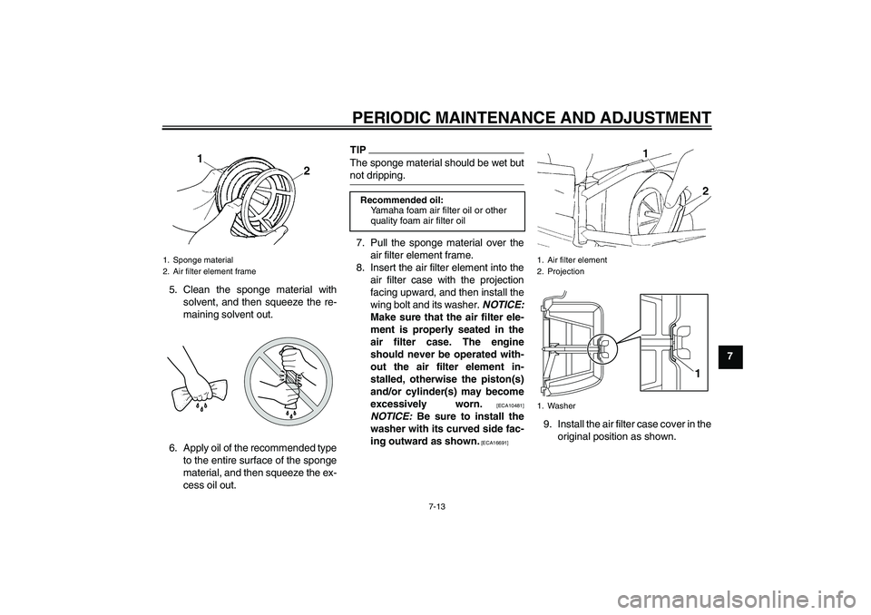
7 5. Clean the sponge material with
solvent, and then squeeze the re-
maining solvent out.
6. Apply oil of the recommended type
to the entire surface of the sponge
material, and then squeeze the ex-
cess oil out.
TIPThe sponge material should be wet but
not dripping.7. Pull the sponge material over the
air filter element frame.
8. Insert the air filter element into the
air filter case with the projection
facing upward, and then install the
wing bolt and its washer. NOTICE:
Make sure that the air filter ele-
ment is properly seated in the
air filter case. The engine
should never be operated with-
out the air filter element in-
stalled, otherwise the piston(s)
and/or cylinder(s) may become
excessively worn.
[ECA10481]
NOTICE: Be sure to install the
washer with its curved side fac-
ing outward as shown.
[ECA16691]
9. Install the air filter case cover in the
original position as shown.
1. Sponge material
2. Air filter element frame
Recommended oil:
Yamaha foam air filter oil or other
quality foam air filter oil
1. Air filter element
2. Projection
1. Washer
1
U5PA89E0.book Page 13 Tuesday, June 15, 2010 10:34 AM
Page 58 of 86

PERIODIC MAINTENANCE AND ADJUSTMENT
7-14
710. Install the seat.
EAU42110
Adjusting the carburetor The carburetor is an important part of
the engine and requires very sophisti-
cated adjustment. Therefore, most car-
buretor adjustments should be left to a
Yamaha dealer, who has the neces-
sary professional knowledge and expe-
rience. The adjustment described in the
following section, however, may be ser-
viced by the owner as part of routine
maintenance.NOTICE
ECA10550
The carburetor has been set and ex-
tensively tested at the Yamaha fac-
tory. Changing these settings
without sufficient technical knowl-
edge may result in poor perfor-
mance of or damage to the engine.
EAU44390
Adjusting the engine idling
speed The engine idling speed must be ad-
justed when necessary.
1. Start the engine and thoroughly
warm it up.
2. Turn the throttle stop screw until
the engine runs at the lowest pos-
sible speed.
3. To increase the engine idling
speed, turn the throttle stop screw
in direction (a). To decrease the
engine idling speed, turn the throt-
tle stop screw in direction (b).1. Throttle stop screw
U5PA89E0.book Page 14 Tuesday, June 15, 2010 10:34 AM