Page 77 of 230

3-21
CHASSIS
CHECKING THE TIRE PRESSURE
1. Measure:
• Tire pressure
Out of specification→Adjust.
• Check the tire while it is cold.
• Loose bead stoppers allow the tire
to slip off its position on the rim
when the tire pressure is low.
• A tilted tire valve stem indicates that
the tire slips off its position on the
rim.
• If the tire valve stem is found tilted,
the tire is considered to be slipping
off its position. Correct the tire posi-
tion.
CHECKING AND TIGHTENING THE
SPOKES
The following procedure applies to all
of the spokes.
1. Check:
• Spokes
Bend/damage→Replace.
Loose spoke→Retighten.
Tap the spokes with a screw-
driver.
A tight spoke will emit a clear, ringing
tone; a loose spoke will sound flat.
2. Tighten:
• Spokes
(with a spoke nipple wrench "1")
Be sure to retighten these spokes be-
fore and after break-in.
CHECKING THE WHEELS
1. Inspect:
• Wheel runout
Elevate the wheel and turn it.
Abnormal runout→ Replace.
2. Inspect:
• Bearing free play
Exist play→Replace.
CHECKING AND ADJUSTING THE
STEERING HEAD
1. Place a stand under the engine to
raise the front wheel off the
ground. WARNING! Securely
support the vehicle so that
there is no danger of it falling
over.
2. Check:
• Steering stem
Grasp the bottom of the forks and
gently rock the fork assembly
back and forth.
Free play→Adjust steering head.3. Check:
• Steering smooth action
Turn the handlebar lock to lock.
Unsmooth action→Adjust steer-
ing ring nut.
4. Adjust:
• Steering ring nut
Steering ring nut adjustment
steps:
a. Remove the number plate.
b. Remove the handlebar and upper
bracket.
c. Loosen the steering ring nut "1"
using the steering nut wrench "2".
d. Tighten the steering ring nut "3"
using steering nut wrench "4".
• Apply the lithium soap base grease
on the thread of the steering stem.
• Set the torque wrench to the steer-
ing nut wrench so that they form a
right angle.
Standard tire pressure:
100 kPa (1.0 kgf/cm2,
15 psi)
Spoke nipple wrench:
YM-01521/90980-01521
Spokes:
3 Nm (0.3 m•kg, 2.2
ft•lb)
Steering nut wrench:
YU-33975/90890-01403
Steering nut wrench:
YU-33975/90890-01403
Steering ring nut (initial
tightening):
38 Nm (3.8 m•kg, 27
ft•lb)
Page 121 of 230
4-40
KICK SHAFT AND SHIFT SHAFT
KICK SHAFT AND SHIFT SHAFT
REMOVING THE KICK SHAFT AND SHIFT SHAFT
Order Part name Q'ty Remarks
Oil pump Refer to "OIL PUMP" section.
1 Kick idle gear 1
2 Kick shaft assembly 1 Refer to removal section.
3 Spring guide 1
4 Torsion spring 1
5 Ratchet wheel 1
6 Kick gear 1
7 Kick shaft 1
8 Washer 1
9 Shift pedal 1
10 Shift shaft 1
11 Collar 1
12 Torsion spring 1
13 Roller 1
14 Shift guide 1 Refer to removal section.
15 Shift lever assembly 1 Refer to removal section.
16 Shift lever 1
Page 123 of 230

4-42
KICK SHAFT AND SHIFT SHAFT
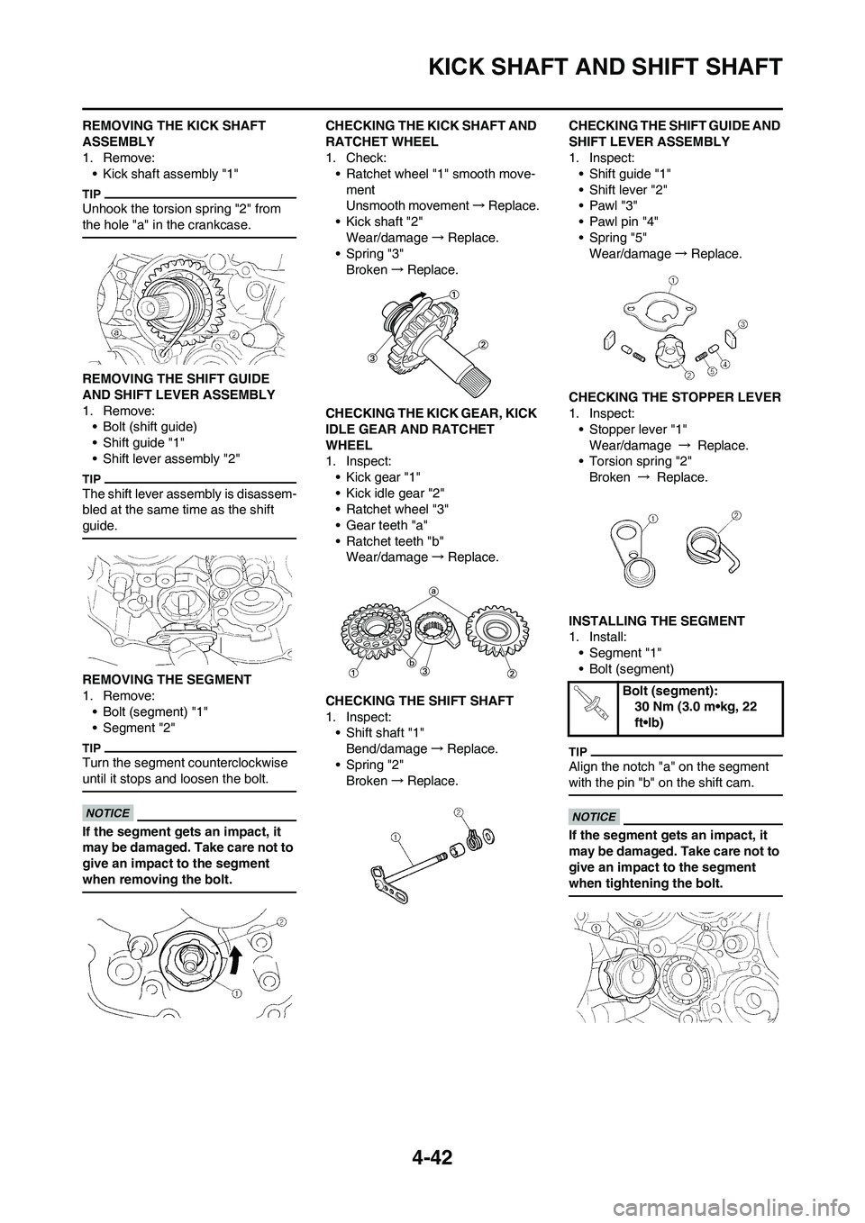
REMOVING THE KICK SHAFT
ASSEMBLY
1. Remove:
• Kick shaft assembly "1"
Unhook the torsion spring "2" from
the hole "a" in the crankcase.
REMOVING THE SHIFT GUIDE
AND SHIFT LEVER ASSEMBLY
1. Remove:
• Bolt (shift guide)
• Shift guide "1"
• Shift lever assembly "2"
The shift lever assembly is disassem-
bled at the same time as the shift
guide.
REMOVING THE SEGMENT
1. Remove:
• Bolt (segment) "1"
• Segment "2"
Turn the segment counterclockwise
until it stops and loosen the bolt.
If the segment gets an impact, it
may be damaged. Take care not to
give an impact to the segment
when removing the bolt.
CHECKING THE KICK SHAFT AND
RATCHET WHEEL
1. Check:
• Ratchet wheel "1" smooth move-
ment
Unsmooth movement→Replace.
• Kick shaft "2"
Wear/damage→Replace.
• Spring "3"
Broken→Replace.
CHECKING THE KICK GEAR, KICK
IDLE GEAR AND RATCHET
WHEEL
1. Inspect:
• Kick gear "1"
• Kick idle gear "2"
• Ratchet wheel "3"
• Gear teeth "a"
• Ratchet teeth "b"
Wear/damage→Replace.
CHECKING THE SHIFT SHAFT
1. Inspect:
• Shift shaft "1"
Bend/damage→Replace.
• Spring "2"
Broken→Replace.CHECKING THE SHIFT GUIDE AND
SHIFT LEVER ASSEMBLY
1. Inspect:
• Shift guide "1"
• Shift lever "2"
•Pawl "3"
• Pawl pin "4"
• Spring "5"
Wear/damage→Replace.
CHECKING THE STOPPER LEVER
1. Inspect:
• Stopper lever "1"
Wear/damage → Replace.
• Torsion spring "2"
Broken → Replace.
INSTALLING THE SEGMENT
1. Install:
• Segment "1"
• Bolt (segment)
Align the notch "a" on the segment
with the pin "b" on the shift cam.
If the segment gets an impact, it
may be damaged. Take care not to
give an impact to the segment
when tightening the bolt.
Bolt (segment):
30 Nm (3.0 m•kg, 22
ft•lb)
Page 124 of 230

4-43
KICK SHAFT AND SHIFT SHAFT
INSTALLING THE STOPPER
LEVER
1. Install:
• Torsion spring "1"
• Washer "2"
• Stopper lever "3"
• Bolt (stopper lever) "4"
Align the stopper lever roller with the
slot on segment.
INSTALLING THE SHIFT GUIDE
AND SHIFT LEVER ASSEMBLY
1. Install:
• Spring "1"
• Pawl pin "2"
•Pawl "3"
To shift lever "4".
Apply the engine oil on the spring,
pawl pin and pawl.
2. Install:
• Shift lever assembly "1"
To shift guide "2".3. Install:
• Shift lever assembly "1"
• Shift guide "2"
• The shift lever assembly is installed
at the same time as the shift guide.
• Apply the engine oil on the bolt
(segment) shaft.
4. Install:
• Bolt (shift guide) "1"
INSTALLING THE SHIFT SHAFT
1. Install:
• Roller "1"
• Collar "2"
• Torsion spring "3"
• Washer "4"
• Shift shaft "5"
Apply the engine oil on the roller and
shift shaft.
2. Install:
• Shift pedal "1"
• Bolt (shift pedal) "2"
Align the punch mark "a" on the shift
shaft with the notch "b" in the shift
pedal.
INSTALLING THE KICK SHAFT
ASSEMBLY
1. Install:
• Kick gear "1"
• Washer "2"
• Circlip "3"
• Ratchet wheel "4"
• Spring "5"
• Washer "6"
• Circlip "7"
To kick shaft "8".
• Apply the molybdenum disulfide oil
on the inner circumferences of the
kick gear and ratchet wheel.
• Align the punch mark "a" on the
ratchet wheel with the punch mark
"b" on the kick shaft.
2. Install:
• Torsion spring "1"
To kick shaft "2".
Make sure the stopper "a" of the tor-
sion spring fits into the hole "b" on the
kick shaft.
Bolt (stopper lever):
10 Nm (1.0 m•kg, 7.2
ft•lb)
Bolt (shift guide):
10 Nm (1.0 m•kg, 7.2
ft•lb)
Bolt (shift pedal):
12 Nm (1.2 m•kg, 8.7
ft•lb)
Page 125 of 230
4-44
KICK SHAFT AND SHIFT SHAFT
3. Install:
• Spring guide "1"
Slide the spring guide into the kick
shaft, make sure the groove "a" in the
spring guide fits on the stopper of the
torsion spring.
4. Install:
• Kick shaft assembly "1"
• Washer "2"
• Apply the molybdenum disulfide
grease on the contacting surfaces
of the kick shaft stopper "a" and kick
shaft ratchet wheel guide "3".
• Apply the engine oil on the kick
shaft.
• Slide the kick shaft assembly into
the crankcase and make sure the
kick shaft stopper "a" fits into the
kick shaft ratchet wheel guide.
5. Hook:
• Torsion spring "1"
Turn the torsion spring clockwise and
hook into the proper hole "a" in the
crankcase.
INSTALLING THE KICK IDLE
GEAR
1. Install:
• Kick idle gear "1"
• Washer "2"
• Circlip "3"
• Apply the engine oil on the kick idle
gear inner circumference.
• Install the kick idle gear with its de-
pressed side "a" toward you.
Page 140 of 230

4-59
TRANSMISSION, SHIFT CAM AND SHIFT FORK
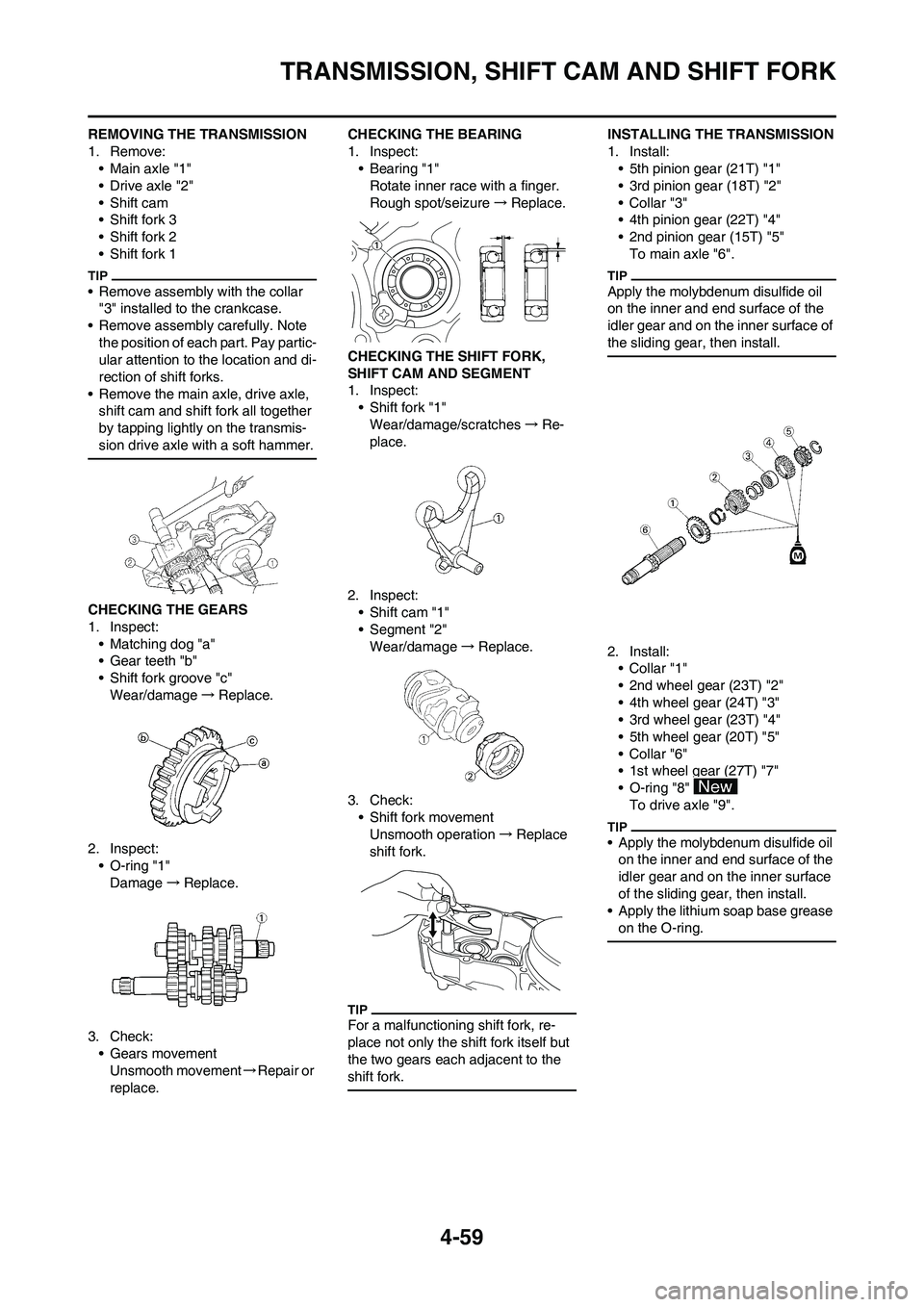
REMOVING THE TRANSMISSION
1. Remove:
• Main axle "1"
• Drive axle "2"
• Shift cam
• Shift fork 3
• Shift fork 2
• Shift fork 1
• Remove assembly with the collar
"3" installed to the crankcase.
• Remove assembly carefully. Note
the position of each part. Pay partic-
ular attention to the location and di-
rection of shift forks.
• Remove the main axle, drive axle,
shift cam and shift fork all together
by tapping lightly on the transmis-
sion drive axle with a soft hammer.
CHECKING THE GEARS
1. Inspect:
• Matching dog "a"
• Gear teeth "b"
• Shift fork groove "c"
Wear/damage→Replace.
2. Inspect:
• O-ring "1"
Damage→Replace.
3. Check:
• Gears movement
Unsmooth movement→Repair or
replace.CHECKING THE BEARING
1. Inspect:
•Bearing "1"
Rotate inner race with a finger.
Rough spot/seizure→Replace.
CHECKING THE SHIFT FORK,
SHIFT CAM AND SEGMENT
1. Inspect:
• Shift fork "1"
Wear/damage/scratches→Re-
place.
2. Inspect:
• Shift cam "1"
• Segment "2"
Wear/damage→Replace.
3. Check:
• Shift fork movement
Unsmooth operation→Replace
shift fork.
For a malfunctioning shift fork, re-
place not only the shift fork itself but
the two gears each adjacent to the
shift fork.
INSTALLING THE TRANSMISSION
1. Install:
• 5th pinion gear (21T) "1"
• 3rd pinion gear (18T) "2"
•Collar "3"
• 4th pinion gear (22T) "4"
• 2nd pinion gear (15T) "5"
To main axle "6".
Apply the molybdenum disulfide oil
on the inner and end surface of the
idler gear and on the inner surface of
the sliding gear, then install.
2. Install:
•Collar "1"
• 2nd wheel gear (23T) "2"
• 4th wheel gear (24T) "3"
• 3rd wheel gear (23T) "4"
• 5th wheel gear (20T) "5"
•Collar "6"
• 1st wheel gear (27T) "7"
• O-ring "8"
To drive axle "9".
• Apply the molybdenum disulfide oil
on the inner and end surface of the
idler gear and on the inner surface
of the sliding gear, then install.
• Apply the lithium soap base grease
on the O-ring.
Page 141 of 230

4-60
TRANSMISSION, SHIFT CAM AND SHIFT FORK
3. Install:
• Washer "1"
• Circlip "2"
• Be sure the circlip sharp-edged cor-
ner "a" is positioned opposite side
to the washer and gear "b".
• Install the circlip with its ends "c"
settled evenly on the spline crests.
4. Install:
•Collar "1"
• Apply the lithium soap base grease
on the oil seal lip.
• When installing the collar into the
crankcase, pay careful attention to
the crankcase oil seal lip.
5. Install:
• Shift fork 1 (L) "1"
• Shift fork 2 (C) "2"
• Shift fork 3 (R) "3"
• Shift cam "4"
To main axle and drive axle.
• Apply the molybdenum disulfide oil
on the shift fork grooves.
• Apply engine oil to the shift cam
groove, bearing contact surface
and shift fork shaft.
• Mesh the shift fork #1 (L) with the
4th wheel gear "5" and #3 (R) with
the 5th wheel gear "7" on the drive
axle.
• Mesh the shift fork #2 (C) with the
3rd pinion gear "6" on the main ax-
le.
6. Install:
• Transmission assembly "1"
To left crankcase "2".
Apply the engine oil on the bearings
and guide bars.
7. Check:
• Shifter operation
• Transmission operation
Unsmooth operation→Repair.
Page 142 of 230
5-1
FRONT WHEEL AND REAR WHEEL
CHASSIS
This section is intended for those who have basic knowledge and skill concerning the servicing of Yamaha motorcycles
(e.g., Yamaha dealers, service engineers, etc.) Those who have little knowledge and skill concerning servicing are request-
ed not to undertake inspection, adjustment, disassembly, or reassembly only by reference to this manual. It may lead to
servicing trouble and mechanical damage.
FRONT WHEEL AND REAR WHEEL
REMOVING THE FRONT WHEEL
Order Part name Q'ty Remarks Hold the machine by placing the suitable stand
under the engine. Refer to "HANDLING NOTE".
1 Bolt (axle holder) 4 Only loosening.
2 Nut (front wheel axle) 1
3 Front wheel axle 1
4 Front wheel 1
5 Collar 2
6 Oil seal 2
7 Bearing 2 Refer to removal section.
8 Brake disc 1