2011 YAMAHA YZ125LC transmission oil
[x] Cancel search: transmission oilPage 49 of 166
3-8
ENGINE
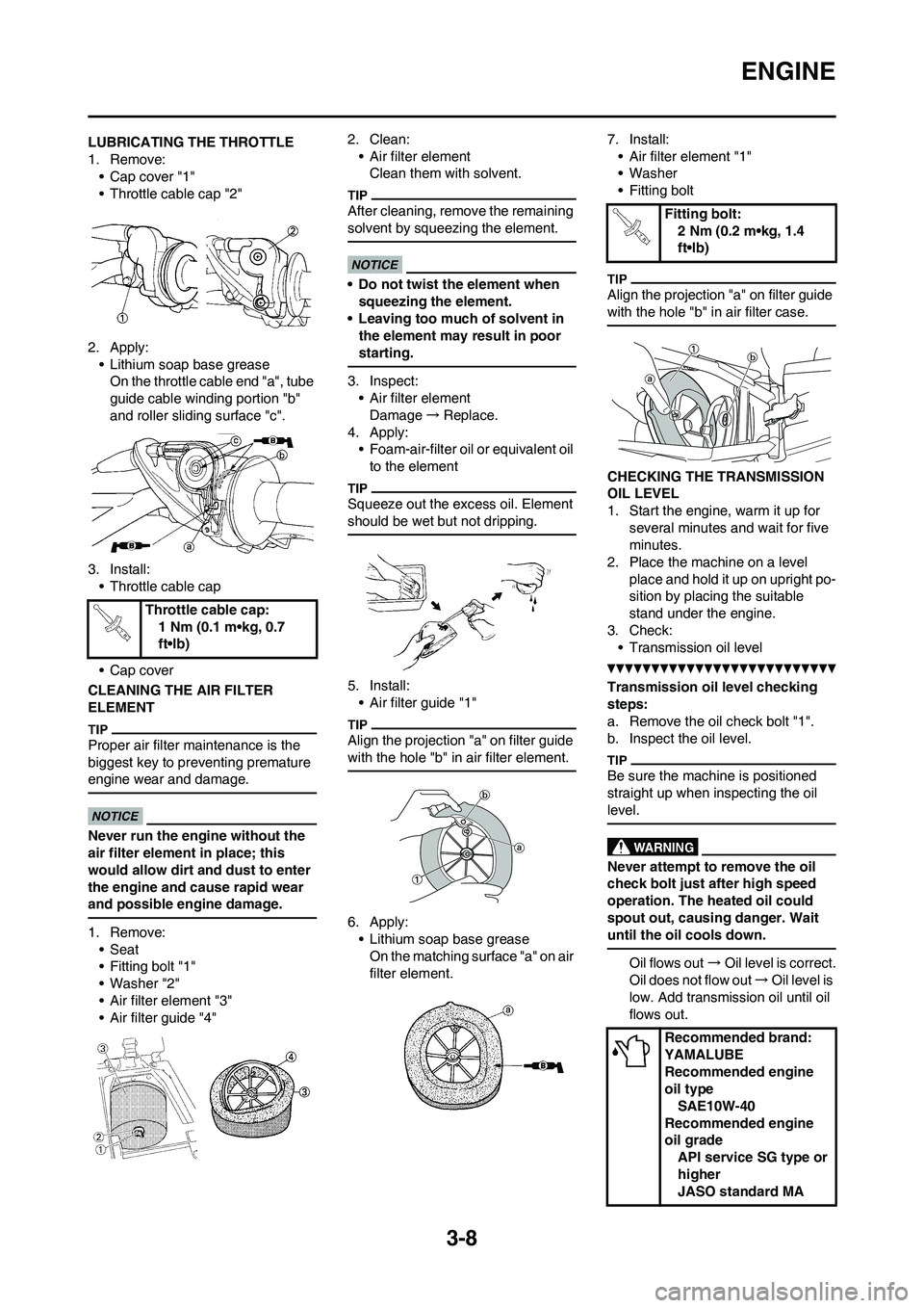
LUBRICATING THE THROTTLE
1. Remove:
• Cap cover "1"
• Throttle cable cap "2"
2. Apply:
• Lithium soap base grease
On the throttle cable end "a", tube
guide cable winding portion "b"
and roller sliding surface "c".
3. Install:
• Throttle cable cap
• Cap cover
CLEANING THE AIR FILTER
ELEMENT
Proper air filter maintenance is the
biggest key to preventing premature
engine wear and damage.
Never run the engine without the
air filter element in place; this
would allow dirt and dust to enter
the engine and cause rapid wear
and possible engine damage.
1. Remove:
• Seat
• Fitting bolt "1"
• Washer "2"
• Air filter element "3"
• Air filter guide "4"2. Clean:
• Air filter element
Clean them with solvent.
After cleaning, remove the remaining
solvent by squeezing the element.
• Do not twist the element when
squeezing the element.
• Leaving too much of solvent in
the element may result in poor
starting.
3. Inspect:
• Air filter element
Damage→Replace.
4. Apply:
• Foam-air-filter oil or equivalent oil
to the element
Squeeze out the excess oil. Element
should be wet but not dripping.
5. Install:
• Air filter guide "1"
Align the projection "a" on filter guide
with the hole "b" in air filter element.
6. Apply:
• Lithium soap base grease
On the matching surface "a" on air
filter element.7. Install:
• Air filter element "1"
• Washer
• Fitting bolt
Align the projection "a" on filter guide
with the hole "b" in air filter case.
CHECKING THE TRANSMISSION
OIL LEVEL
1. Start the engine, warm it up for
several minutes and wait for five
minutes.
2. Place the machine on a level
place and hold it up on upright po-
sition by placing the suitable
stand under the engine.
3. Check:
• Transmission oil level
Transmission oil level checking
steps:
a. Remove the oil check bolt "1".
b. Inspect the oil level.
Be sure the machine is positioned
straight up when inspecting the oil
level.
Never attempt to remove the oil
check bolt just after high speed
operation. The heated oil could
spout out, causing danger. Wait
until the oil cools down.
Oil flows out→Oil level is correct.
Oil does not flow out→Oil level is
low. Add transmission oil until oil
flows out. Throttle cable cap:
1 Nm (0.1 m•kg, 0.7
ft•lb)
Fitting bolt:
2 Nm (0.2 m•kg, 1.4
ft•lb)
Recommended brand:
YAMALUBE
Recommended engine
oil type
SAE10W-40
Recommended engine
oil grade
API service SG type or
higher
JASO standard MA
Page 50 of 166
3-9
CHASSIS
c. Inspect the gasket (oil check bolt),
replace if damaged.
d. Tighten the oil check bolt.
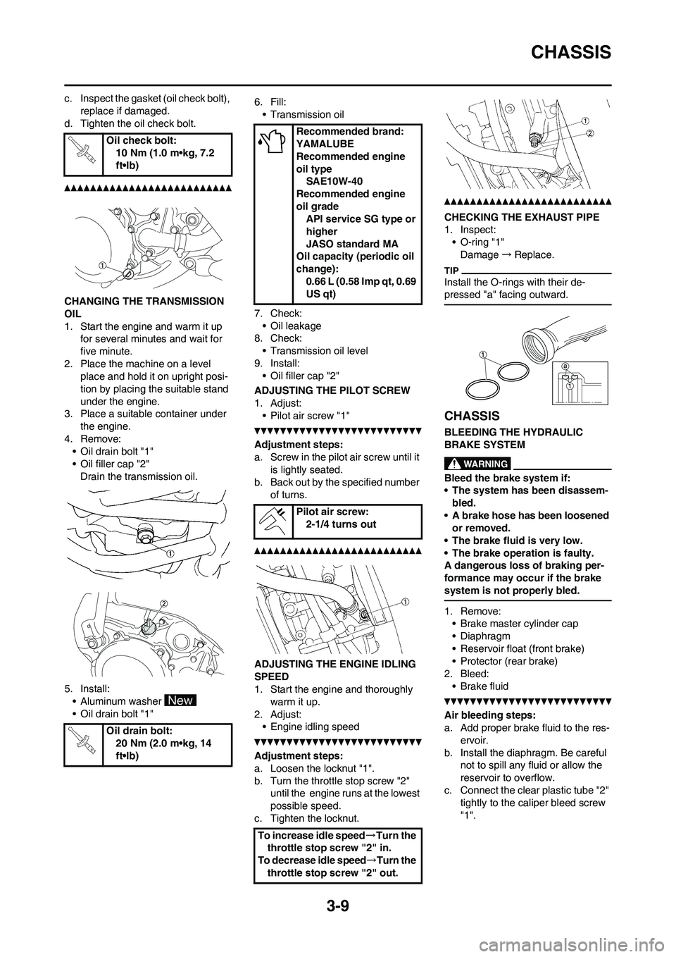
CHANGING THE TRANSMISSION
OIL
1. Start the engine and warm it up
for several minutes and wait for
five minute.
2. Place the machine on a level
place and hold it on upright posi-
tion by placing the suitable stand
under the engine.
3. Place a suitable container under
the engine.
4. Remove:
• Oil drain bolt "1"
• Oil filler cap "2"
Drain the transmission oil.
5. Install:
• Aluminum washer
• Oil drain bolt "1"6. Fill:
• Transmission oil
7. Check:
• Oil leakage
8. Check:
• Transmission oil level
9. Install:
• Oil filler cap "2"
ADJUSTING THE PILOT SCREW
1. Adjust:
• Pilot air screw "1"
Adjustment steps:
a. Screw in the pilot air screw until it
is lightly seated.
b. Back out by the specified number
of turns.
ADJUSTING THE ENGINE IDLING
SPEED
1. Start the engine and thoroughly
warm it up.
2. Adjust:
• Engine idling speed
Adjustment steps:
a. Loosen the locknut "1".
b. Turn the throttle stop screw "2"
until the engine runs at the lowest
possible speed.
c. Tighten the locknut.
CHECKING THE EXHAUST PIPE
1. Inspect:
• O-ring "1"
Damage→Replace.
Install the O-rings with their de-
pressed "a" facing outward.
CHASSIS
BLEEDING THE HYDRAULIC
BRAKE SYSTEM
Bleed the brake system if:
• The system has been disassem-
bled.
• A brake hose has been loosened
or removed.
• The brake fluid is very low.
• The brake operation is faulty.
A dangerous loss of braking per-
formance may occur if the brake
system is not properly bled.
1. Remove:
• Brake master cylinder cap
• Diaphragm
• Reservoir float (front brake)
• Protector (rear brake)
2. Bleed:
• Brake fluid
Air bleeding steps:
a. Add proper brake fluid to the res-
ervoir.
b. Install the diaphragm. Be careful
not to spill any fluid or allow the
reservoir to overflow.
c. Connect the clear plastic tube "2"
tightly to the caliper bleed screw
"1". Oil check bolt:
10 Nm (1.0 m•kg, 7.2
ft•lb)
Oil drain bolt:
20 Nm (2.0 m•kg, 14
ft•lb)
Recommended brand:
YAMALUBE
Recommended engine
oil type
SAE10W-40
Recommended engine
oil grade
API service SG type or
higher
JASO standard MA
Oil capacity (periodic oil
change):
0.66 L (0.58 Imp qt, 0.69
US qt)
Pilot air screw:
2-1/4 turns out
To increase idle speed→Turn the
throttle stop screw "2" in.
To decrease idle speed→Turn the
throttle stop screw "2" out.
Page 79 of 166
4-19
CLUTCH
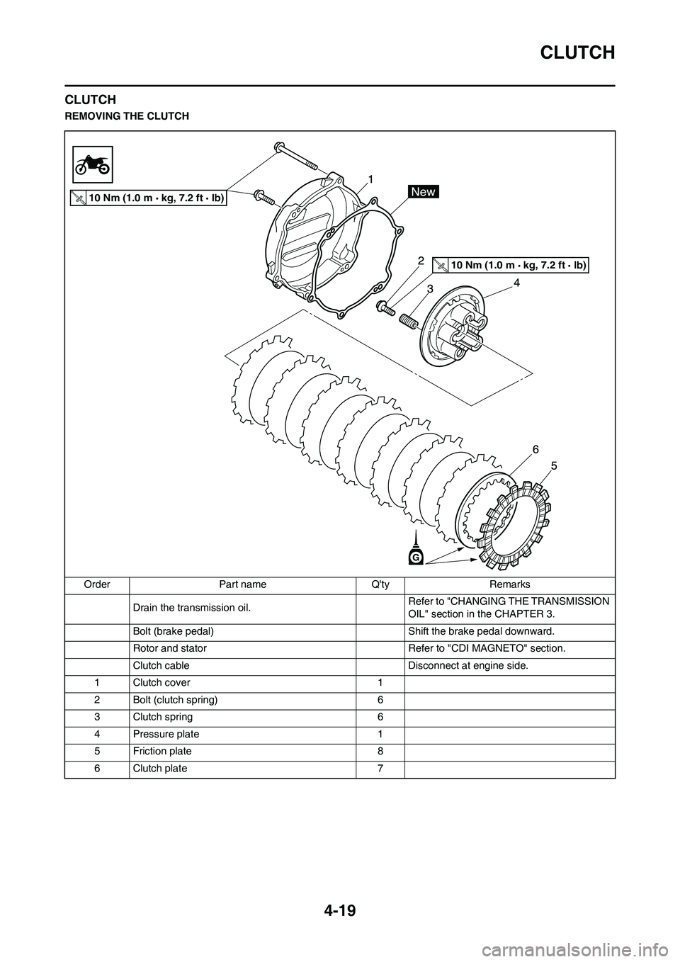
CLUTCH
REMOVING THE CLUTCH
Order Part name Q'ty Remarks
Drain the transmission oil.Refer to "CHANGING THE TRANSMISSION
OIL" section in the CHAPTER 3.
Bolt (brake pedal) Shift the brake pedal downward.
Rotor and stator Refer to "CDI MAGNETO" section.
Clutch cable Disconnect at engine side.
1 Clutch cover 1
2 Bolt (clutch spring) 6
3 Clutch spring 6
4 Pressure plate 1
5 Friction plate 8
6 Clutch plate 7
10 Nm (1.0 m kg, 7.2 ft lb)
10 Nm (1.0 m kg, 7.2 ft lb)
Page 81 of 166
4-21
CLUTCH
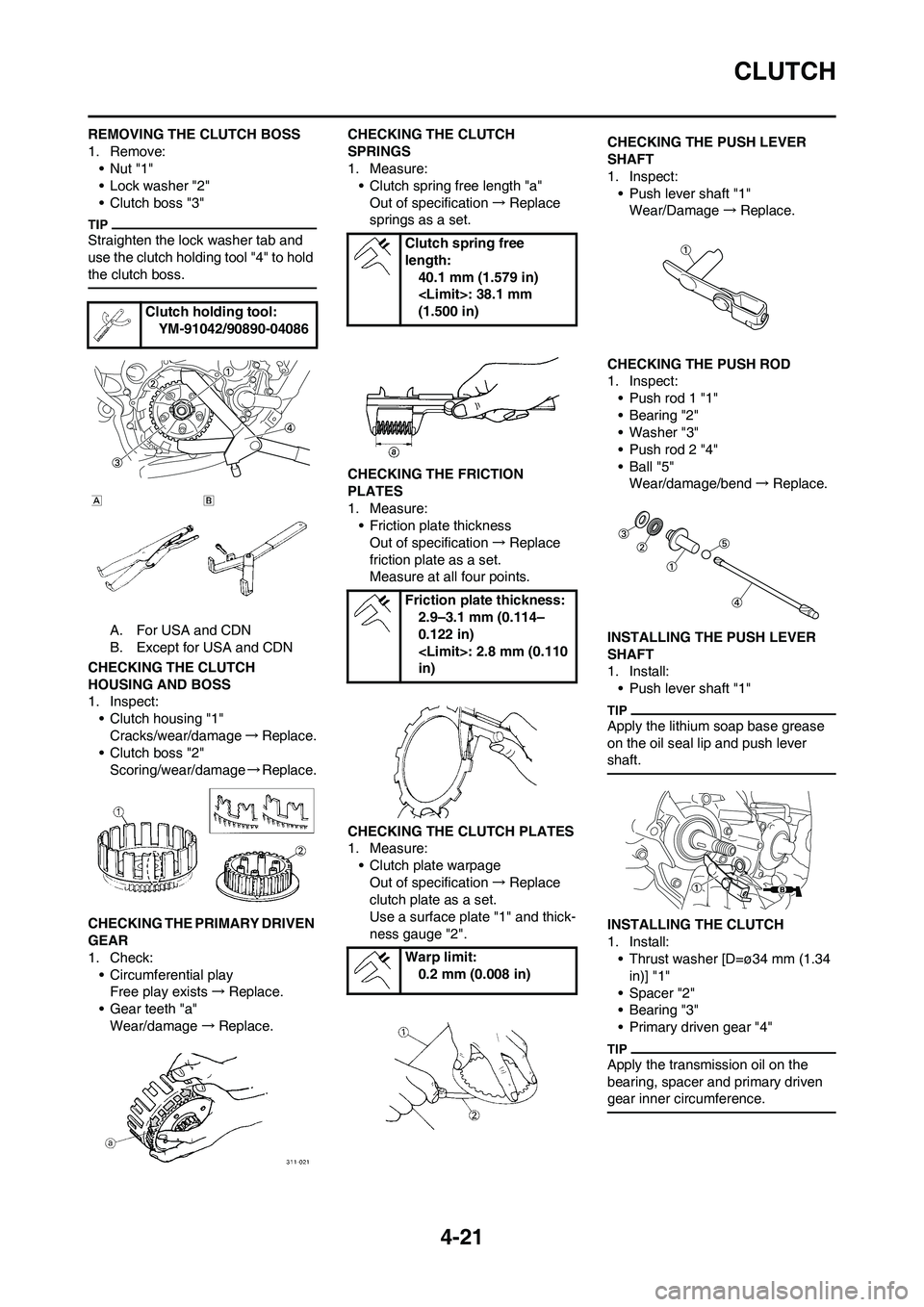
REMOVING THE CLUTCH BOSS
1. Remove:
•Nut "1"
• Lock washer "2"
• Clutch boss "3"
Straighten the lock washer tab and
use the clutch holding tool "4" to hold
the clutch boss.
A. For USA and CDN
B. Except for USA and CDN
CHECKING THE CLUTCH
HOUSING AND BOSS
1. Inspect:
• Clutch housing "1"
Cracks/wear/damage→Replace.
• Clutch boss "2"
Scoring/wear/damage→Replace.
CHECKING THE PRIMARY DRIVEN
GEAR
1. Check:
• Circumferential play
Free play exists→Replace.
• Gear teeth "a"
Wear/damage→Replace.CHECKING THE CLUTCH
SPRINGS
1. Measure:
• Clutch spring free length "a"
Out of specification→Replace
springs as a set.
CHECKING THE FRICTION
PLATES
1. Measure:
• Friction plate thickness
Out of specification→Replace
friction plate as a set.
Measure at all four points.
CHECKING THE CLUTCH PLATES
1. Measure:
• Clutch plate warpage
Out of specification→Replace
clutch plate as a set.
Use a surface plate "1" and thick-
ness gauge "2".CHECKING THE PUSH LEVER
SHAFT
1. Inspect:
• Push lever shaft "1"
Wear/Damage→Replace.
CHECKING THE PUSH ROD
1. Inspect:
• Push rod 1 "1"
• Bearing "2"
• Washer "3"
• Push rod 2 "4"
•Ball "5"
Wear/damage/bend→Replace.
INSTALLING THE PUSH LEVER
SHAFT
1. Install:
• Push lever shaft "1"
Apply the lithium soap base grease
on the oil seal lip and push lever
shaft.
INSTALLING THE CLUTCH
1. Install:
• Thrust washer [D=ø34 mm (1.34
in)] "1"
• Spacer "2"
• Bearing "3"
• Primary driven gear "4"
Apply the transmission oil on the
bearing, spacer and primary driven
gear inner circumference.
Clutch holding tool:
YM-91042/90890-04086
Clutch spring free
length:
40.1 mm (1.579 in)
(1.500 in)
Friction plate thickness:
2.9–3.1 mm (0.114–
0.122 in)
in)
Warp limit:
0.2 mm (0.008 in)
Page 82 of 166
![YAMAHA YZ125LC 2011 Owners Manual 4-22
CLUTCH
2. Install:
• Thrust washer [D=ø34 mm (1.34
in)] "1"
• Clutch boss "2"
3. Install:
• Lock washer "1"
• Nut (clutch boss) "2"
Use the clutch holding tool "3" to hold
the clutc YAMAHA YZ125LC 2011 Owners Manual 4-22
CLUTCH
2. Install:
• Thrust washer [D=ø34 mm (1.34
in)] "1"
• Clutch boss "2"
3. Install:
• Lock washer "1"
• Nut (clutch boss) "2"
Use the clutch holding tool "3" to hold
the clutc](/manual-img/51/53908/w960_53908-81.png)
4-22
CLUTCH
2. Install:
• Thrust washer [D=ø34 mm (1.34
in)] "1"
• Clutch boss "2"
3. Install:
• Lock washer "1"
• Nut (clutch boss) "2"
Use the clutch holding tool "3" to hold
the clutch boss.
A. For USA and CDN
B. Except for USA and CDN
4. Bend the lock washer "1" tab.5. Install:
• Friction plate "1"
• Clutch plate "2"
• Install the clutch plates and friction
plates alternately on the clutch
boss, starting with a friction plate
and ending with a friction plate.
• Apply the transmission oil on the
friction plates and clutch plates.
6. Install:
•Bearing "1"
• Washer "2"
• Circlip "3"
To push rod 1 "4".
Apply the lithium soap base grease
on the bearing and washer.
7. Install:
• Push rod 2 "1"
• Ball "2"
• Push rod 1 "3"
Apply the transmission oil on the
push rod 1, 2 and ball.
8. Install:
• Pressure plate "1"9. Install:
• Clutch spring "1"
• Bolt (clutch spring) "2"
Tighten the bolts in stage, using a
crisscross pattern.
10. Install:
• Dowel pin "1"
• Gasket (clutch cover) "2"
11. Install:
• Clutch cover "1"
• Bolt (clutch cover)
Tighten the bolts in stage, using a
crisscross pattern.
12. Install:
• O-ring "1"
• Clutch cable "2"
Apply the lithium soap base grease
on the O-ring.
Nut (clutch boss):
80 Nm (8.0 m•kg, 58
ft•lb)
Clutch holding tool:
YM-91042/90890-04086
Bolt (clutch spring):
10 Nm (1.0 m•kg, 7.2
ft•lb)
Bolt (clutch cover):
10 Nm (1.0 m•kg, 7.2
ft•lb)
Page 83 of 166
4-23
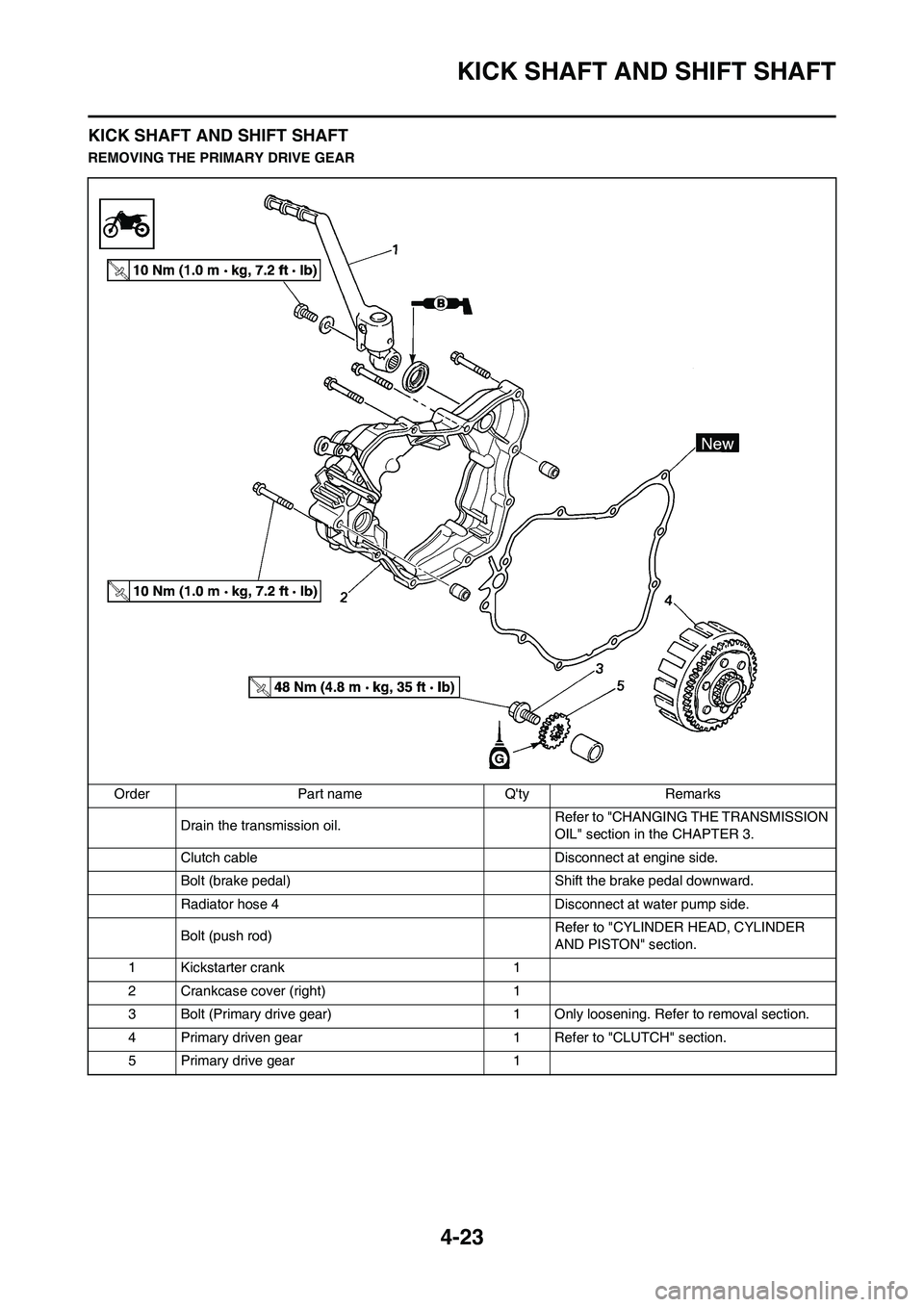
KICK SHAFT AND SHIFT SHAFT
KICK SHAFT AND SHIFT SHAFT
REMOVING THE PRIMARY DRIVE GEAR
Order Part name Q'ty Remarks
Drain the transmission oil. Refer to "CHANGING THE TRANSMISSION
OIL" section in the CHAPTER 3.
Clutch cable Disconnect at engine side.
Bolt (brake pedal) Shift the brake pedal downward.
Radiator hose 4 Disconnect at water pump side.
Bolt (push rod)Refer to "CYLINDER HEAD, CYLINDER
AND PISTON" section.
1 Kickstarter crank 1
2 Crankcase cover (right) 1
3 Bolt (Primary drive gear) 1 Only loosening. Refer to removal section.
4 Primary driven gear 1 Refer to "CLUTCH" section.
5 Primary drive gear 1
Page 86 of 166
4-26
KICK SHAFT AND SHIFT SHAFT
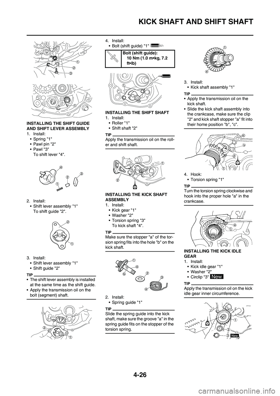
INSTALLING THE SHIFT GUIDE
AND SHIFT LEVER ASSEMBLY
1. Install:
• Spring "1"
• Pawl pin "2"
•Pawl "3"
To shift lever "4".
2. Install:
• Shift lever assembly "1"
To shift guide "2".
3. Install:
• Shift lever assembly "1"
• Shift guide "2"
• The shift lever assembly is installed
at the same time as the shift guide.
• Apply the transmission oil on the
bolt (segment) shaft.
4. Install:
• Bolt (shift guide) "1"
INSTALLING THE SHIFT SHAFT
1. Install:
• Roller "1"
• Shift shaft "2"
Apply the transmission oil on the roll-
er and shift shaft.
INSTALLING THE KICK SHAFT
ASSEMBLY
1. Install:
• Kick gear "1"
• Washer "2"
• Torsion spring "3"
To kick shaft "4".
Make sure the stopper "a" of the tor-
sion spring fits into the hole "b" on the
kick shaft.
2. Install:
• Spring guide "1"
Slide the spring guide into the kick
shaft, make sure the groove "a" in the
spring guide fits on the stopper of the
torsion spring.
3. Install:
• Kick shaft assembly "1"
• Apply the transmission oil on the
kick shaft.
• Slide the kick shaft assembly into
the crankcase, make sure the clip
"2" and kick shaft stopper "a" fit into
their home position "b", "c".
4. Hook:
• Torsion spring "1"
Turn the torsion spring clockwise and
hook into the proper hole "a" in the
crankcase.
INSTALLING THE KICK IDLE
GEAR
1. Install:
• Kick idle gear "1"
• Washer "2"
• Circlip "3"
Apply the transmission oil on the kick
idle gear inner circumference.
Bolt (shift guide):
10 Nm (1.0 m•kg, 7.2
ft•lb)
Page 89 of 166
4-29
YPVS GOVERNOR
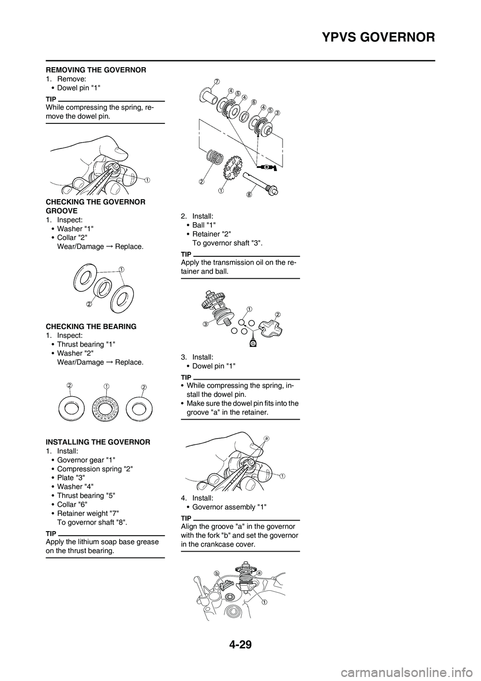
REMOVING THE GOVERNOR
1. Remove:
• Dowel pin "1"
While compressing the spring, re-
move the dowel pin.
CHECKING THE GOVERNOR
GROOVE
1. Inspect:
• Washer "1"
•Collar "2"
Wear/Damage→Replace.
CHECKING THE BEARING
1. Inspect:
• Thrust bearing "1"
• Washer "2"
Wear/Damage→Replace.
INSTALLING THE GOVERNOR
1. Install:
• Governor gear "1"
• Compression spring "2"
• Plate "3"
• Washer "4"
• Thrust bearing "5"
•Collar "6"
• Retainer weight "7"
To governor shaft "8".
Apply the lithium soap base grease
on the thrust bearing.
2. Install:
• Ball "1"
• Retainer "2"
To governor shaft "3".
Apply the transmission oil on the re-
tainer and ball.
3. Install:
• Dowel pin "1"
• While compressing the spring, in-
stall the dowel pin.
• Make sure the dowel pin fits into the
groove "a" in the retainer.
4. Install:
• Governor assembly "1"
Align the groove "a" in the governor
with the fork "b" and set the governor
in the crankcase cover.