2011 YAMAHA YZ125LC torque
[x] Cancel search: torquePage 58 of 166
3-17
CHASSIS
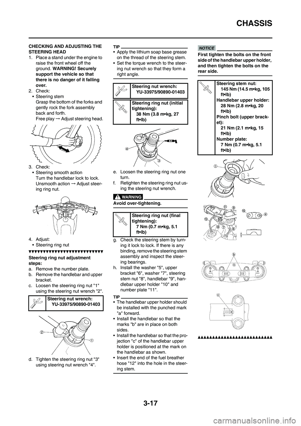
CHECKING AND ADJUSTING THE
STEERING HEAD
1. Place a stand under the engine to
raise the front wheel off the
ground. WARNING! Securely
support the vehicle so that
there is no danger of it falling
over.
2. Check:
• Steering stem
Grasp the bottom of the forks and
gently rock the fork assembly
back and forth.
Free play→Adjust steering head.
3. Check:
• Steering smooth action
Turn the handlebar lock to lock.
Unsmooth action→Adjust steer-
ing ring nut.
4. Adjust:
• Steering ring nut
Steering ring nut adjustment
steps:
a. Remove the number plate.
b. Remove the handlebar and upper
bracket.
c. Loosen the steering ring nut "1"
using the steering nut wrench "2".
d. Tighten the steering ring nut "3"
using steering nut wrench "4".
• Apply the lithium soap base grease
on the thread of the steering stem.
• Set the torque wrench to the steer-
ing nut wrench so that they form a
right angle.
e. Loosen the steering ring nut one
turn.
f. Retighten the steering ring nut us-
ing the steering nut wrench.
Avoid over-tightening.
g. Check the steering stem by turn-
ing it lock to lock. If there is any
binding, remove the steering stem
assembly and inspect the steer-
ing bearings.
h. Install the washer "5", upper
bracket "6", washer "7", steering
stem nut "8", handlebar "9", han-
dlebar upper holder "10" and
number plate "11".
• The handlebar upper holder should
be installed with the punched mark
"a" forward.
• Install the handlebar so that the
marks "b" are in place on both
sides.
• Install the handlebar so that the pro-
jection "c" of the handlebar upper
holder is positioned at the mark on
the handlebar as shown.
• Insert the end of the fuel breather
hose "12" into the hole in the steer-
ing stem.
First tighten the bolts on the front
side of the handlebar upper holder,
and then tighten the bolts on the
rear side.
Steering nut wrench:
YU-33975/90890-01403
Steering nut wrench:
YU-33975/90890-01403
Steering ring nut (initial
tightening):
38 Nm (3.8 m•kg, 27
ft•lb)
Steering ring nut (final
tightening):
7 Nm (0.7 m•kg, 5.1
ft•lb)Steering stem nut:
145 Nm (14.5 m•kg, 105
ft•lb)
Handlebar upper holder:
28 Nm (2.8 m•kg, 20
ft•lb)
Pinch bolt (upper brack-
et):
21 Nm (2.1 m•kg, 15
ft•lb)
Number plate:
7 Nm (0.7 m•kg, 5.1
ft•lb)
Page 126 of 166
5-20
FRONT FORK
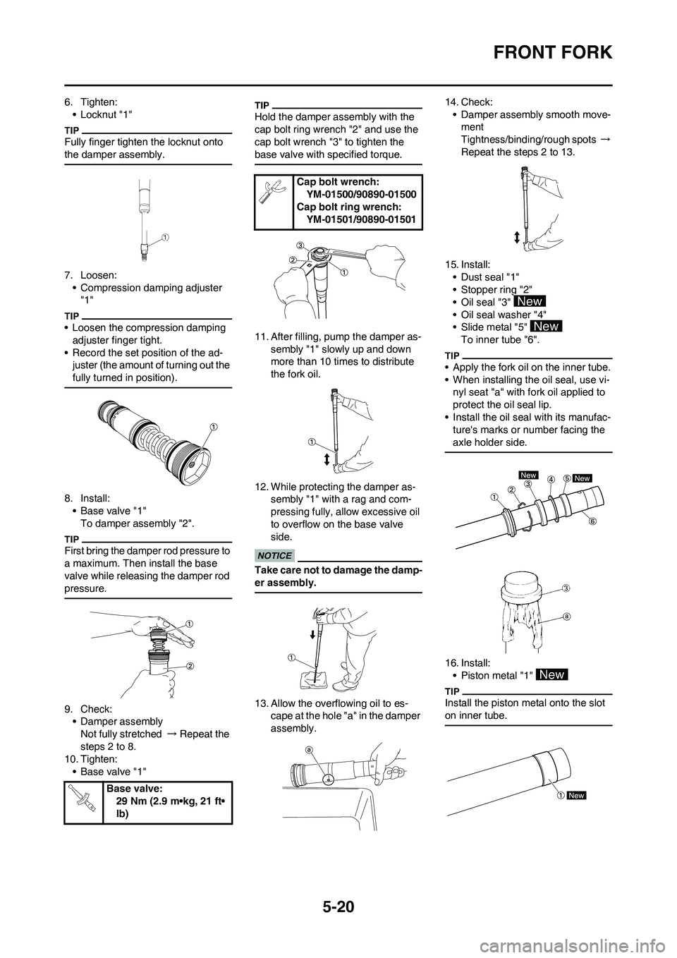
6. Tighten:
• Locknut "1"
Fully finger tighten the locknut onto
the damper assembly.
7. Loosen:
• Compression damping adjuster
"1"
• Loosen the compression damping
adjuster finger tight.
• Record the set position of the ad-
juster (the amount of turning out the
fully turned in position).
8. Install:
• Base valve "1"
To damper assembly "2".
First bring the damper rod pressure to
a maximum. Then install the base
valve while releasing the damper rod
pressure.
9. Check:
• Damper assembly
Not fully stretched → Repeat the
steps 2 to 8.
10. Tighten:
• Base valve "1"
Hold the damper assembly with the
cap bolt ring wrench "2" and use the
cap bolt wrench "3" to tighten the
base valve with specified torque.
11. After filling, pump the damper as-
sembly "1" slowly up and down
more than 10 times to distribute
the fork oil.
12. While protecting the damper as-
sembly "1" with a rag and com-
pressing fully, allow excessive oil
to overflow on the base valve
side.
Take care not to damage the damp-
er assembly.
13. Allow the overflowing oil to es-
cape at the hole "a" in the damper
assembly.14. Check:
• Damper assembly smooth move-
ment
Tightness/binding/rough spots →
Repeat the steps 2 to 13.
15. Install:
• Dust seal "1"
• Stopper ring "2"
• Oil seal "3"
• Oil seal washer "4"
• Slide metal "5"
To inner tube "6".
• Apply the fork oil on the inner tube.
• When installing the oil seal, use vi-
nyl seat "a" with fork oil applied to
protect the oil seal lip.
• Install the oil seal with its manufac-
ture's marks or number facing the
axle holder side.
16. Install:
• Piston metal "1"
Install the piston metal onto the slot
on inner tube.
Base valve:
29 Nm (2.9 m•kg, 21 ft•
lb)
Cap bolt wrench:
YM-01500/90890-01500
Cap bolt ring wrench:
YM-01501/90890-01501
Page 128 of 166
5-22
FRONT FORK
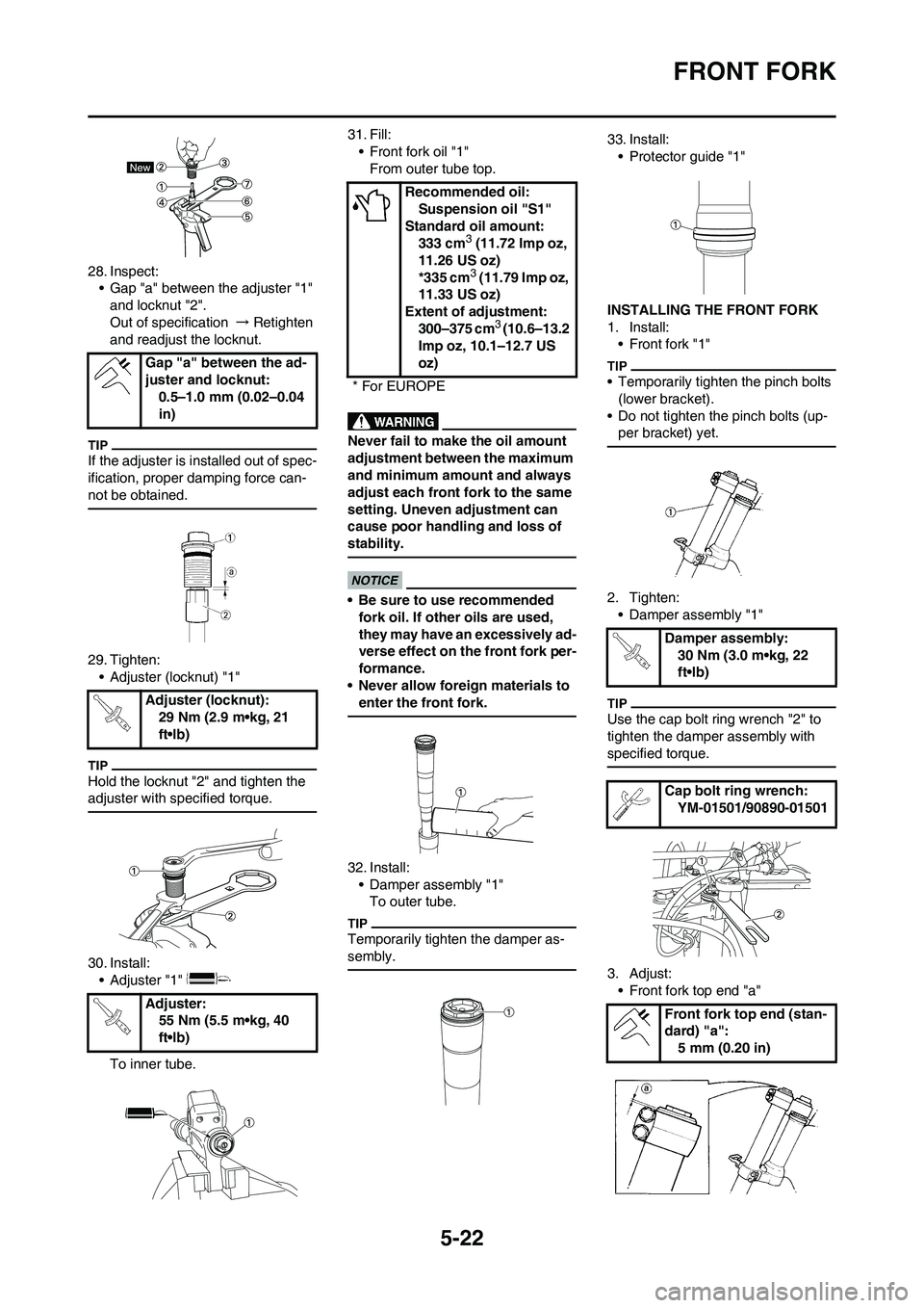
28. Inspect:
• Gap "a" between the adjuster "1"
and locknut "2".
Out of specification → Retighten
and readjust the locknut.
If the adjuster is installed out of spec-
ification, proper damping force can-
not be obtained.
29. Tighten:
• Adjuster (locknut) "1"
Hold the locknut "2" and tighten the
adjuster with specified torque.
30. Install:
• Adjuster "1"
To inner tube.31. Fill:
• Front fork oil "1"
From outer tube top.
Never fail to make the oil amount
adjustment between the maximum
and minimum amount and always
adjust each front fork to the same
setting. Uneven adjustment can
cause poor handling and loss of
stability.
• Be sure to use recommended
fork oil. If other oils are used,
they may have an excessively ad-
verse effect on the front fork per-
formance.
• Never allow foreign materials to
enter the front fork.
32. Install:
• Damper assembly "1"
To outer tube.
Temporarily tighten the damper as-
sembly.
33. Install:
• Protector guide "1"
INSTALLING THE FRONT FORK
1. Install:
• Front fork "1"
• Temporarily tighten the pinch bolts
(lower bracket).
• Do not tighten the pinch bolts (up-
per bracket) yet.
2. Tighten:
• Damper assembly "1"
Use the cap bolt ring wrench "2" to
tighten the damper assembly with
specified torque.
3. Adjust:
• Front fork top end "a" Gap "a" between the ad-
juster and locknut:
0.5–1.0 mm (0.02–0.04
in)
Adjuster (locknut):
29 Nm (2.9 m•kg, 21
ft•lb)
Adjuster:
55 Nm (5.5 m•kg, 40
ft•lb)
Recommended oil:
Suspension oil "S1"
Standard oil amount:
333 cm
3 (11.72 Imp oz,
11.26 US oz)
*335 cm
3 (11.79 Imp oz,
11.33 US oz)
Extent of adjustment:
300–375 cm
3 (10.6–13.2
Imp oz, 10.1–12.7 US
oz)
* For EUROPE
Damper assembly:
30 Nm (3.0 m•kg, 22
ft•lb)
Cap bolt ring wrench:
YM-01501/90890-01501
Front fork top end (stan-
dard) "a":
5 mm (0.20 in)
Page 129 of 166
5-23
FRONT FORK
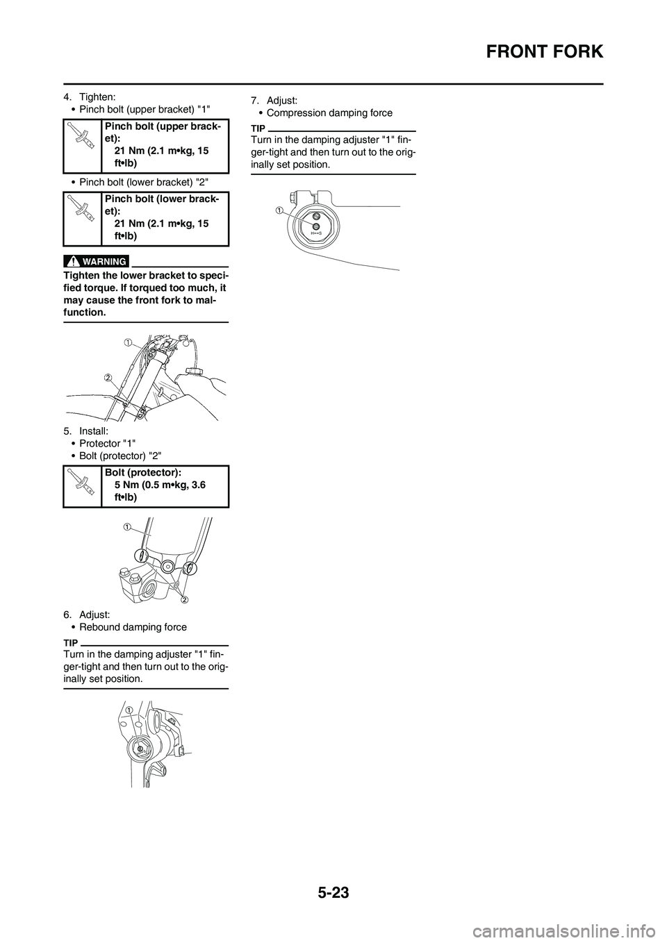
4. Tighten:
• Pinch bolt (upper bracket) "1"
• Pinch bolt (lower bracket) "2"
Tighten the lower bracket to speci-
fied torque. If torqued too much, it
may cause the front fork to mal-
function.
5. Install:
• Protector "1"
• Bolt (protector) "2"
6. Adjust:
• Rebound damping force
Turn in the damping adjuster "1" fin-
ger-tight and then turn out to the orig-
inally set position.
7. Adjust:
• Compression damping force
Turn in the damping adjuster "1" fin-
ger-tight and then turn out to the orig-
inally set position.
Pinch bolt (upper brack-
et):
21 Nm (2.1 m•kg, 15
ft•lb)
Pinch bolt (lower brack-
et):
21 Nm (2.1 m•kg, 15
ft•lb)
Bolt (protector):
5 Nm (0.5 m•kg, 3.6
ft•lb)
Page 138 of 166
5-32
STEERING
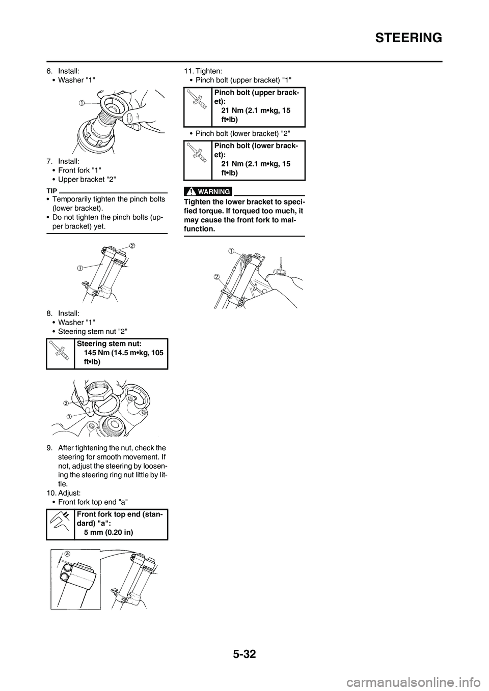
6. Install:
• Washer "1"
7. Install:
• Front fork "1"
• Upper bracket "2"
• Temporarily tighten the pinch bolts
(lower bracket).
• Do not tighten the pinch bolts (up-
per bracket) yet.
8. Install:
• Washer "1"
• Steering stem nut "2"
9. After tightening the nut, check the
steering for smooth movement. If
not, adjust the steering by loosen-
ing the steering ring nut little by lit-
tle.
10. Adjust:
• Front fork top end "a"11. Tighten:
• Pinch bolt (upper bracket) "1"
• Pinch bolt (lower bracket) "2"
Tighten the lower bracket to speci-
fied torque. If torqued too much, it
may cause the front fork to mal-
function.
Steering stem nut:
145 Nm (14.5 m•kg, 105
ft•lb)
Front fork top end (stan-
dard) "a":
5 mm (0.20 in)
Pinch bolt (upper brack-
et):
21 Nm (2.1 m•kg, 15
ft•lb)
Pinch bolt (lower brack-
et):
21 Nm (2.1 m•kg, 15
ft•lb)
Page 163 of 166
7-10
CHASSIS
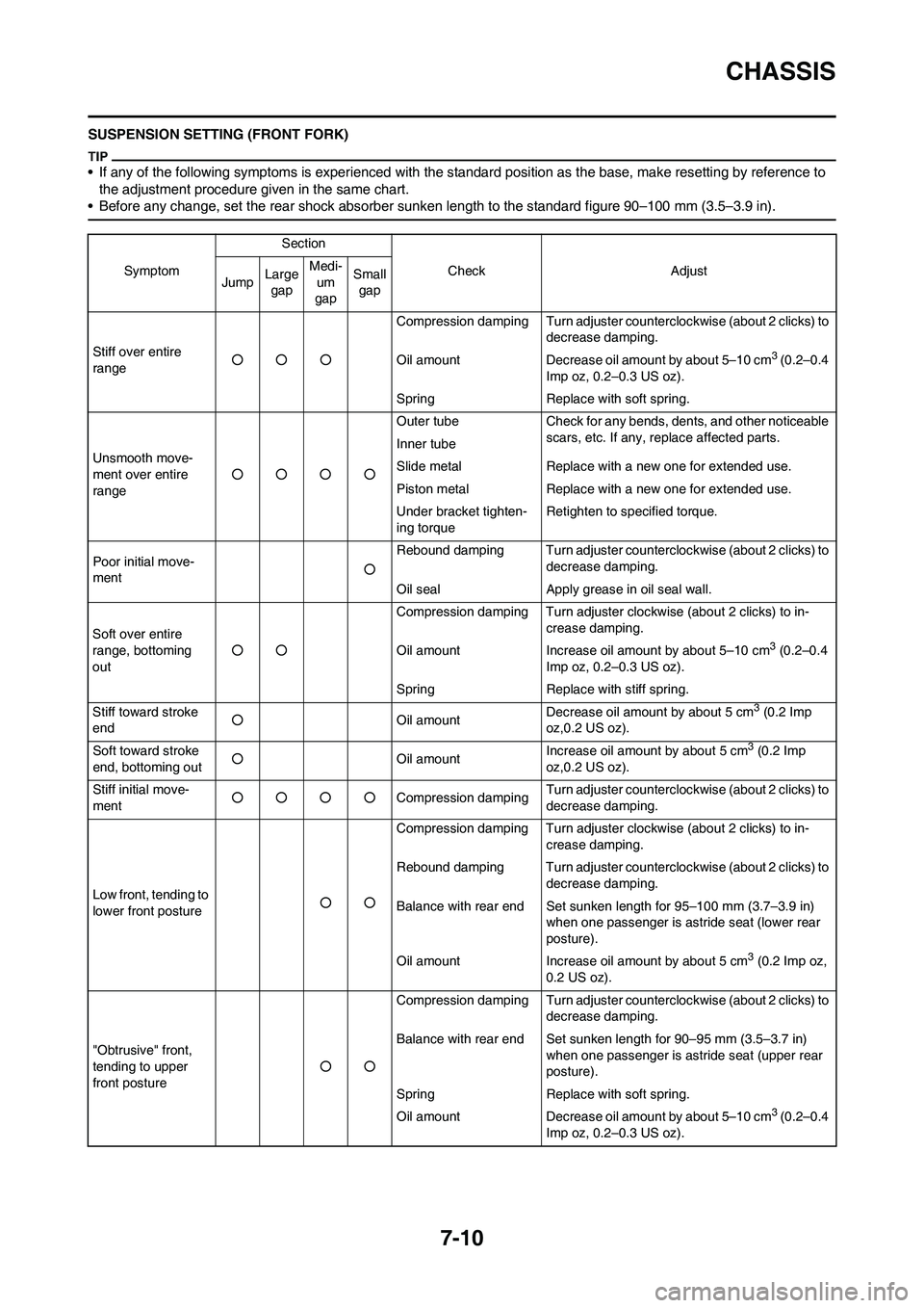
SUSPENSION SETTING (FRONT FORK)
• If any of the following symptoms is experienced with the standard position as the base, make resetting by reference to
the adjustment procedure given in the same chart.
• Before any change, set the rear shock absorber sunken length to the standard figure 90–100 mm (3.5–3.9 in).
SymptomSection
Check Adjust
JumpLarge
gapMedi-
um
gapSmall
gap
Stiff over entire
range○○○Compression damping Turn adjuster counterclockwise (about 2 clicks) to
decrease damping.
Oil amount Decrease oil amount by about 5–10 cm
3 (0.2–0.4
Imp oz, 0.2–0.3 US oz).
Spring Replace with soft spring.
Unsmooth move-
ment over entire
range○○○○Outer tube Check for any bends, dents, and other noticeable
scars, etc. If any, replace affected parts.
Inner tube
Slide metal Replace with a new one for extended use.
Piston metal Replace with a new one for extended use.
Under bracket tighten-
ing torqueRetighten to specified torque.
Poor initial move-
ment○Rebound damping Turn adjuster counterclockwise (about 2 clicks) to
decrease damping.
Oil seal Apply grease in oil seal wall.
Soft over entire
range, bottoming
out○○Compression damping Turn adjuster clockwise (about 2 clicks) to in-
crease damping.
Oil amount Increase oil amount by about 5–10 cm
3 (0.2–0.4
Imp oz, 0.2–0.3 US oz).
Spring Replace with stiff spring.
Stiff toward stroke
end○Oil amountDecrease oil amount by about 5 cm
3 (0.2 Imp
oz,0.2 US oz).
Soft toward stroke
end, bottoming out○Oil amountIncrease oil amount by about 5 cm
3 (0.2 Imp
oz,0.2 US oz).
Stiff initial move-
ment○○○○Compression dampingTurn adjuster counterclockwise (about 2 clicks) to
decrease damping.
Low front, tending to
lower front posture○○Compression damping Turn adjuster clockwise (about 2 clicks) to in-
crease damping.
Rebound damping Turn adjuster counterclockwise (about 2 clicks) to
decrease damping.
Balance with rear end Set sunken length for 95–100 mm (3.7–3.9 in)
when one passenger is astride seat (lower rear
posture).
Oil amount Increase oil amount by about 5 cm
3 (0.2 Imp oz,
0.2 US oz).
"Obtrusive" front,
tending to upper
front posture○○Compression damping Turn adjuster counterclockwise (about 2 clicks) to
decrease damping.
Balance with rear end Set sunken length for 90–95 mm (3.5–3.7 in)
when one passenger is astride seat (upper rear
posture).
Spring Replace with soft spring.
Oil amount Decrease oil amount by about 5–10 cm
3 (0.2–0.4
Imp oz, 0.2–0.3 US oz).