2011 YAMAHA YZ125LC air filter
[x] Cancel search: air filterPage 49 of 166
3-8
ENGINE
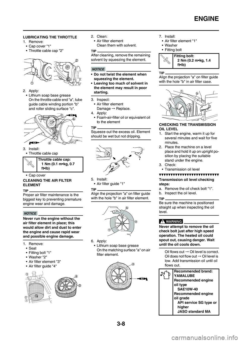
LUBRICATING THE THROTTLE
1. Remove:
• Cap cover "1"
• Throttle cable cap "2"
2. Apply:
• Lithium soap base grease
On the throttle cable end "a", tube
guide cable winding portion "b"
and roller sliding surface "c".
3. Install:
• Throttle cable cap
• Cap cover
CLEANING THE AIR FILTER
ELEMENT
Proper air filter maintenance is the
biggest key to preventing premature
engine wear and damage.
Never run the engine without the
air filter element in place; this
would allow dirt and dust to enter
the engine and cause rapid wear
and possible engine damage.
1. Remove:
• Seat
• Fitting bolt "1"
• Washer "2"
• Air filter element "3"
• Air filter guide "4"2. Clean:
• Air filter element
Clean them with solvent.
After cleaning, remove the remaining
solvent by squeezing the element.
• Do not twist the element when
squeezing the element.
• Leaving too much of solvent in
the element may result in poor
starting.
3. Inspect:
• Air filter element
Damage→Replace.
4. Apply:
• Foam-air-filter oil or equivalent oil
to the element
Squeeze out the excess oil. Element
should be wet but not dripping.
5. Install:
• Air filter guide "1"
Align the projection "a" on filter guide
with the hole "b" in air filter element.
6. Apply:
• Lithium soap base grease
On the matching surface "a" on air
filter element.7. Install:
• Air filter element "1"
• Washer
• Fitting bolt
Align the projection "a" on filter guide
with the hole "b" in air filter case.
CHECKING THE TRANSMISSION
OIL LEVEL
1. Start the engine, warm it up for
several minutes and wait for five
minutes.
2. Place the machine on a level
place and hold it up on upright po-
sition by placing the suitable
stand under the engine.
3. Check:
• Transmission oil level
Transmission oil level checking
steps:
a. Remove the oil check bolt "1".
b. Inspect the oil level.
Be sure the machine is positioned
straight up when inspecting the oil
level.
Never attempt to remove the oil
check bolt just after high speed
operation. The heated oil could
spout out, causing danger. Wait
until the oil cools down.
Oil flows out→Oil level is correct.
Oil does not flow out→Oil level is
low. Add transmission oil until oil
flows out. Throttle cable cap:
1 Nm (0.1 m•kg, 0.7
ft•lb)
Fitting bolt:
2 Nm (0.2 m•kg, 1.4
ft•lb)
Recommended brand:
YAMALUBE
Recommended engine
oil type
SAE10W-40
Recommended engine
oil grade
API service SG type or
higher
JASO standard MA
Page 62 of 166
4-2
SEAT, FUEL TANK AND SIDE COVERS
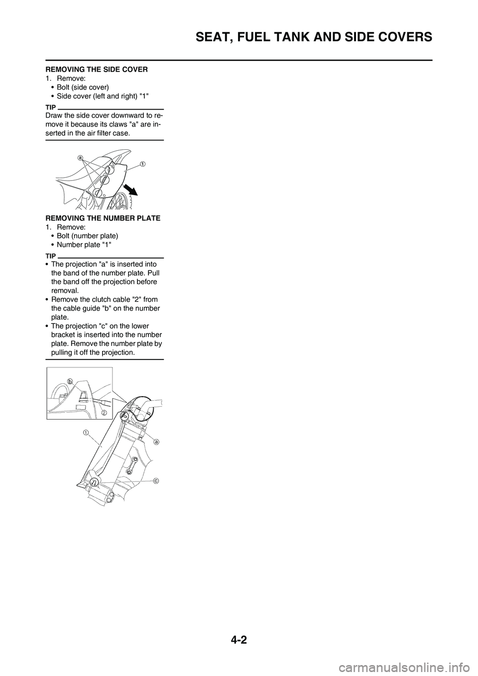
REMOVING THE SIDE COVER
1. Remove:
• Bolt (side cover)
• Side cover (left and right) "1"
Draw the side cover downward to re-
move it because its claws "a" are in-
serted in the air filter case.
REMOVING THE NUMBER PLATE
1. Remove:
• Bolt (number plate)
• Number plate "1"
• The projection "a" is inserted into
the band of the number plate. Pull
the band off the projection before
removal.
• Remove the clutch cable "2" from
the cable guide "b" on the number
plate.
• The projection "c" on the lower
bracket is inserted into the number
plate. Remove the number plate by
pulling it off the projection.
Page 69 of 166
4-9
CARBURETOR AND REED VALVE
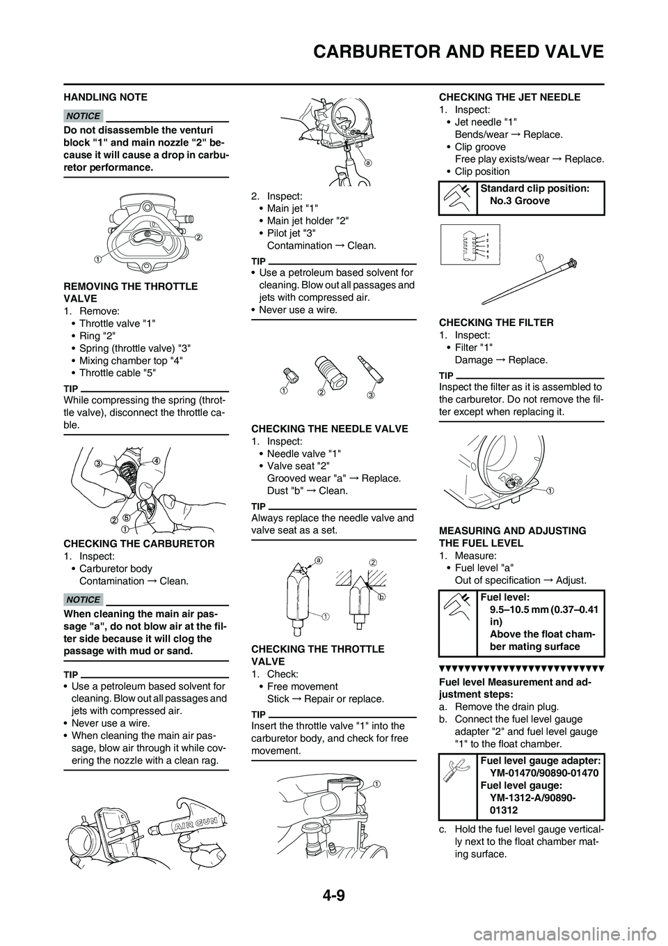
HANDLING NOTE
Do not disassemble the venturi
block "1" and main nozzle "2" be-
cause it will cause a drop in carbu-
retor performance.
REMOVING THE THROTTLE
VALVE
1. Remove:
• Throttle valve "1"
• Ring "2"
• Spring (throttle valve) "3"
• Mixing chamber top "4"
• Throttle cable "5"
While compressing the spring (throt-
tle valve), disconnect the throttle ca-
ble.
CHECKING THE CARBURETOR
1. Inspect:
• Carburetor body
Contamination→Clean.
When cleaning the main air pas-
sage "a", do not blow air at the fil-
ter side because it will clog the
passage with mud or sand.
• Use a petroleum based solvent for
cleaning. Blow out all passages and
jets with compressed air.
• Never use a wire.
• When cleaning the main air pas-
sage, blow air through it while cov-
ering the nozzle with a clean rag.
2. Inspect:
•Main jet "1"
• Main jet holder "2"
• Pilot jet "3"
Contamination→Clean.
• Use a petroleum based solvent for
cleaning. Blow out all passages and
jets with compressed air.
• Never use a wire.
CHECKING THE NEEDLE VALVE
1. Inspect:
• Needle valve "1"
• Valve seat "2"
Grooved wear "a" →Replace.
Dust "b" →Clean.
Always replace the needle valve and
valve seat as a set.
CHECKING THE THROTTLE
VALVE
1. Check:
• Free movement
Stick→Repair or replace.
Insert the throttle valve "1" into the
carburetor body, and check for free
movement.
CHECKING THE JET NEEDLE
1. Inspect:
• Jet needle "1"
Bends/wear→Replace.
• Clip groove
Free play exists/wear→Replace.
• Clip position
CHECKING THE FILTER
1. Inspect:
•Filter "1"
Damage→Replace.
Inspect the filter as it is assembled to
the carburetor. Do not remove the fil-
ter except when replacing it.
MEASURING AND ADJUSTING
THE FUEL LEVEL
1. Measure:
• Fuel level "a"
Out of specification→Adjust.
Fuel level Measurement and ad-
justment steps:
a. Remove the drain plug.
b. Connect the fuel level gauge
adapter "2" and fuel level gauge
"1" to the float chamber.
c. Hold the fuel level gauge vertical-
ly next to the float chamber mat-
ing surface.
Standard clip position:
No.3 Groove
Fuel level:
9.5–10.5 mm (0.37–0.41
in)
Above the float cham-
ber mating surface
Fuel level gauge adapter:
YM-01470/90890-01470
Fuel level gauge:
YM-1312-A/90890-
01312
Page 71 of 166
4-11
CARBURETOR AND REED VALVE
• After installing the needle valve to
the float, install them to the carbure-
tor.
• Check the float for smooth move-
ment.
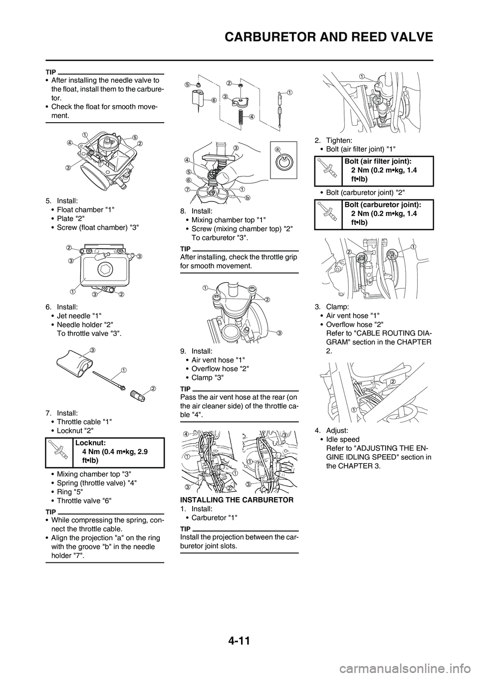
5. Install:
• Float chamber "1"
• Plate "2"
• Screw (float chamber) "3"
6. Install:
• Jet needle "1"
• Needle holder "2"
To throttle valve "3".
7. Install:
• Throttle cable "1"
• Locknut "2"
• Mixing chamber top "3"
• Spring (throttle valve) "4"
• Ring "5"
• Throttle valve "6"
• While compressing the spring, con-
nect the throttle cable.
• Align the projection "a" on the ring
with the groove "b" in the needle
holder "7".
8. Install:
• Mixing chamber top "1"
• Screw (mixing chamber top) "2"
To carburetor "3".
After installing, check the throttle grip
for smooth movement.
9. Install:
• Air vent hose "1"
• Overflow hose "2"
•Clamp "3"
Pass the air vent hose at the rear (on
the air cleaner side) of the throttle ca-
ble "4".
INSTALLING THE CARBURETOR
1. Install:
• Carburetor "1"
Install the projection between the car-
buretor joint slots.
2. Tighten:
• Bolt (air filter joint) "1"
• Bolt (carburetor joint) "2"
3. Clamp:
• Air vent hose "1"
• Overflow hose "2"
Refer to "CABLE ROUTING DIA-
GRAM" section in the CHAPTER
2.
4. Adjust:
• Idle speed
Refer to "ADJUSTING THE EN-
GINE IDLING SPEED" section in
the CHAPTER 3. Locknut:
4 Nm (0.4 m•kg, 2.9
ft•lb)
Bolt (air filter joint):
2 Nm (0.2 m•kg, 1.4
ft•lb)
Bolt (carburetor joint):
2 Nm (0.2 m•kg, 1.4
ft•lb)
Page 144 of 166
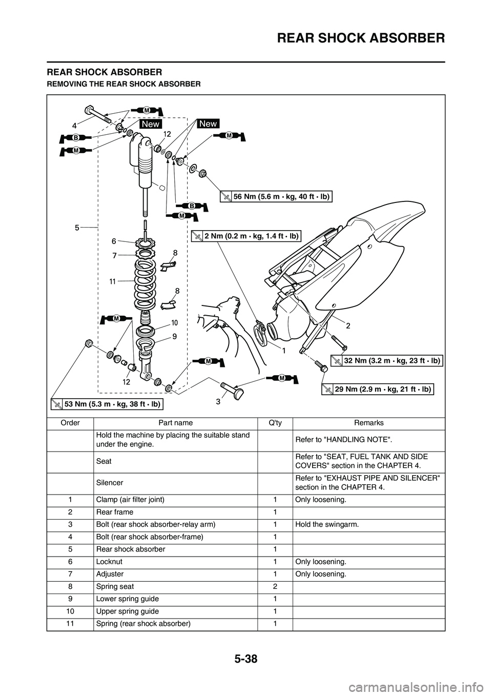
5-38
REAR SHOCK ABSORBER
REAR SHOCK ABSORBER
REMOVING THE REAR SHOCK ABSORBER
Order Part name Q'ty Remarks
Hold the machine by placing the suitable stand
under the engine.Refer to "HANDLING NOTE".
Seat Refer to "SEAT, FUEL TANK AND SIDE
COVERS" section in the CHAPTER 4.
Silencer Refer to "EXHAUST PIPE AND SILENCER"
section in the CHAPTER 4.
1 Clamp (air filter joint) 1 Only loosening.
2Rear frame 1
3 Bolt (rear shock absorber-relay arm) 1 Hold the swingarm.
4 Bolt (rear shock absorber-frame) 1
5 Rear shock absorber 1
6 Locknut 1 Only loosening.
7 Adjuster 1 Only loosening.
8 Spring seat 2
9 Lower spring guide 1
10 Upper spring guide 1
11 Spring (rear shock absorber) 1
53 Nm (5.3 m kg, 38 ft lb)
56 Nm (5.6 m kg, 40 ft lb)
2 Nm (0.2 m kg, 1.4 ft lb)
32 Nm (3.2 m kg, 23 ft lb)
29 Nm (2.9 m kg, 21 ft lb)
Page 148 of 166
![YAMAHA YZ125LC 2011 Owners Manual 5-42
REAR SHOCK ABSORBER
6. Install:
• Rear frame "1"
• Bolt [rear frame (upper)] "2"
• Bolt [rear frame (lower)] "3"
7. Tighten:
• Bolt (air filter joint) "1"Bolt [rear frame (upper)]:
32 Nm YAMAHA YZ125LC 2011 Owners Manual 5-42
REAR SHOCK ABSORBER
6. Install:
• Rear frame "1"
• Bolt [rear frame (upper)] "2"
• Bolt [rear frame (lower)] "3"
7. Tighten:
• Bolt (air filter joint) "1"Bolt [rear frame (upper)]:
32 Nm](/manual-img/51/53908/w960_53908-147.png)
5-42
REAR SHOCK ABSORBER
6. Install:
• Rear frame "1"
• Bolt [rear frame (upper)] "2"
• Bolt [rear frame (lower)] "3"
7. Tighten:
• Bolt (air filter joint) "1"Bolt [rear frame (upper)]:
32 Nm (3.2 m•kg, 23
ft•lb)
Bolt [rear frame (lower)]:
29 Nm (2.9 m•kg, 21
ft•lb)
Bolt (air filter joint):
2 Nm (0.2 m•kg, 1.4
ft•lb)
Page 157 of 166

7-4
ENGINE
ROAD CONDITION AND EXAMPLES OF CARBURETOR SETTING
A. For USA and CDN
B. Except for USA and CDN
SPECIFICATIONS OF JET NEEDLE
EXAMPLES OF CARBURETOR SETTING DEPENDING ON SYMPTOM General condition Sandy condition
Under 10°C (50°F) 15–25°C (59–
77°F) Over 30°C
(86°F) Under 10°C
(50°F) 15–25°C (59–
77°F) Over 30°C
(86°F
(Winter) (Spring, Au- tumn)(Summer) (Winter) (Spring, Au-
tumn)(Summer)
Main jet #440 #430 #420 #460 #450 #440
Jet needle 6BFY44-74-3 6BFY43-74-3 6BFY44- 74-2 6BFY43-74-4 6BFY44-74-3 6BFY43-74-3
Pilot jet A #42.5 #40 #40 #42.5 #40 #40 B #47.5 #45 #42.5 #47.5 #45 #42.5
Pilot air screw 2-1/4 2-1/4 2-1/4 2-1/4 2-1/4 2-1/4
Diameter of straight portion
ø2.72 mm
(0.1071 in) ø2.73 mm
(0.1075 in) ø2.74 mm
(0.1079 in) ø2.75 mm
(0.1083 in) ø2.76 mm
(0.1087 in)
Rich 1 richer 6BFY43-72-4 6BFY43-73-4 6BFY43-74-4 6BFY43-75-4 6BFY43-76-4
0.5 richer 6BFY44-72-3 6BFY44-73-3 6BFY44-74-3 6BFY44-75-3 6BFY44-76-3
6BFY42-72-4 6BFY42-73-4 6BFY42-74-4 6BFY42-75-4 6BFY42-76-4
STD 6BFY43-72-3 6BFY43-73-3 6BFY43-74-3 6BFY43-75-3 6BFY43-76-3
0.5 leaner 6BFY44-72-2 6BFY44-73-2 6BFY44-74-2 6BFY44-75-2 6BFY44-76-2
6BFY42-72-3 6BFY42-73-3 6BFY42-74-3 6BFY42-75-3 6BFY42-76-3
Lean 1 leaner 6BFY43-72-2 6BFY43-73-2 6BFY43-74-2 6BFY43-75-2 6BFY43-76-2
Symptom Setting Checking
At full throttle Stall at high speeds
*Hard breathing
Shearing noise
Whitish spark plug ↓
Lean mixture Increase main jet calibration no. (Gradual-
ly)
Discoloration of spark plug
→If tan color, it
is in good condition.
If cannot be corrected: Clogged float valve seat
Clogged fuel hose
Clogged fuel cock
At full throttle Stop of speed pick-up
Slow speed pick-up
Slow response
Sooty spark plug ↓
Rich mixture Decrease main jet calibration no. (Gradual-
ly)
*In case of racing slig
ht enrichment of mix-
ture reduces engine trouble. Discoloration of spark plug
→If tan color, it
is in good condition.
If not effect: Clogged air filter
Fuel overflow from carburetor
Clogged main air passage or clogged fil-
ter
Page 158 of 166

7-5
ENGINE
This should be taken simply for an example. It is necessary to set the carburetor while checking the operating conditions
of the engine and discoloration of spark plugs. Normally, carb uretor setting is made by means of the main jet, jet needle
clip position (including one with 0.5 difference), pilot jet and pilot air screw. If the result of setting is still unsatisfactory, it is
advisable to change the diameter of the straight portion the jet needle.
Lean mixture Lower jet needle clip position. (1 groove
down)
Clip position indicates the position of jet
needle groove, to which the clip is fitted.
The position is numbered from the top.
If a change in the clip position (1 groove) is
effective, try another jet needle that pro-
vides a difference of 0. 5 in the clip position.
Rich mixture Raise jet needle clip position. (1 groove up)
1/4–3/4 throttle
*Hard breathing
Lack of speed Lower jet needle clip position. (1 groove
down)
1/4–1/2 throttle Slow speed pick-up
White smoke
Poor acceleration Raise jet needle clip position. (1 groove up)
0–1/4 throttle *Hard breathing
Speed down Use jet needle having a smaller diameter. Number of turns-back
→Correct properly
Overflow from carburetor
0–1/4 throttle Poor acceleration
White smoke Use jet needle with a larger diameter.
Unstable at low speeds Pinking noise Lower jet needle clip position.
(1 groove down)
Turn in pilot air screw.
Poor response at extremely low
speed Reduce pilot jet calibration No.
Turn out pilot air screw.
If not effect, reverse the above procedures. Dragging brake
Overflow from carburetor
Poor response in the range of
low to intermediate speeds Raise jet needle clip position.
If no effect, reverse the above procedures.
Poor response when throttle is
opened quickly Check overall settings.
Use main jet having lower calibration no.
Raise jet needle clip position. (1 groove up)
If no effect, reverse the above procedures. Check air filter for fouling.
Poor engine operation Turn in pilot ai r screw. Check throttle valve operation.
* In case of hard breathing, check the air vent hose for clogging. Symptom Setting CheckingGroove 1
Groove 2
Groove 3
Groove 4
Groove 5
Clip
Jet needle
Leaner
(Standard)
Richer