Page 35 of 140
4-17
4 spring preload. With each complete turn of the
adjusting nut, distance A is changed by 1.5 mm
(0.06 in).
3. Tighten the locknut to the specified torque.
NOTICEECB00080Always tighten the locknut against the adjust-
ing nut, and then tighten it to the specifiedtorque.
Rebound damping force
Turn the adjusting screw in direction (a) to increase
the rebound damping force and thereby harden the
damping, and in direction (b) to decrease the re-
bound damping force and thereby soften the
damping. Spring preload setting:
Minimum (hard):
Distance A = 197.6 mm (7.78 in)
Standard:
Distance A = 206.0 mm (8.11 in)
Maximum (soft):
Distance A = 209.6 mm (8.25 in)
1. Distance A
1
Tightening torque:
Locknut:
42 Nm (4.2 m·kgf, 30 ft·lbf)
U33B70E0.book Page 17 Wednesday, June 11, 2008 1:38 PM
Page 39 of 140
4-21
4
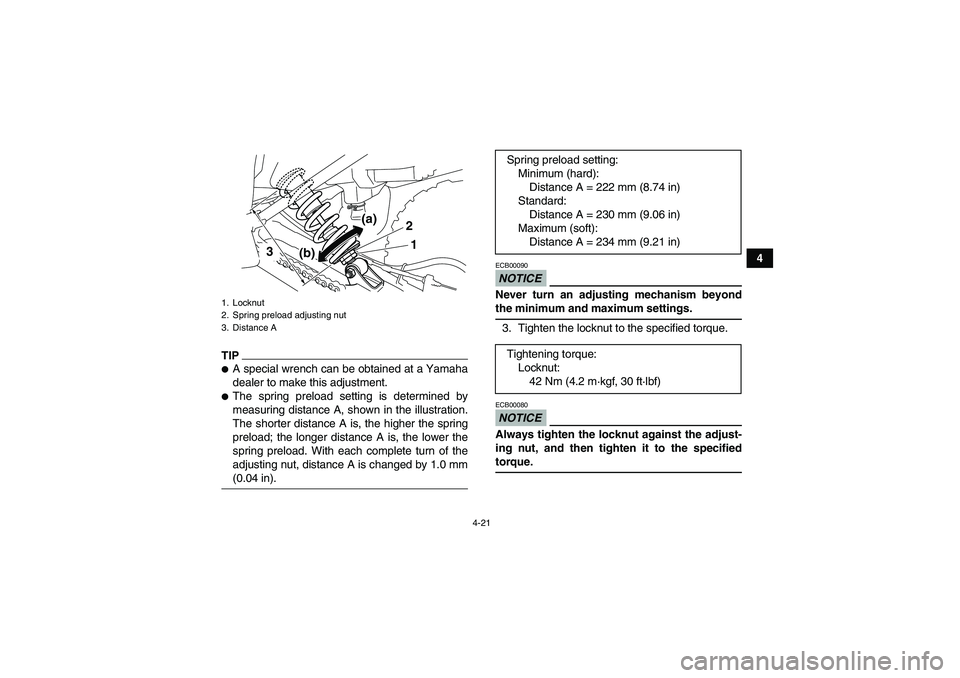
TIP�A special wrench can be obtained at a Yamaha
dealer to make this adjustment.�The spring preload setting is determined by
measuring distance A, shown in the illustration.
The shorter distance A is, the higher the spring
preload; the longer distance A is, the lower the
spring preload. With each complete turn of the
adjusting nut, distance A is changed by 1.0 mm(0.04 in).
NOTICEECB00090Never turn an adjusting mechanism beyondthe minimum and maximum settings.
3. Tighten the locknut to the specified torque.NOTICEECB00080Always tighten the locknut against the adjust-
ing nut, and then tighten it to the specifiedtorque.
1. Locknut
2. Spring preload adjusting nut
3. Distance A
2
1
(b) 3(a)
Spring preload setting:
Minimum (hard):
Distance A = 222 mm (8.74 in)
Standard:
Distance A = 230 mm (9.06 in)
Maximum (soft):
Distance A = 234 mm (9.21 in)
Tightening torque:
Locknut:
42 Nm (4.2 m·kgf, 30 ft·lbf)
U33B70E0.book Page 21 Wednesday, June 11, 2008 1:38 PM
Page 41 of 140
4-23
4 2. Turn the adjusting nut in direction (a) to in-
crease the spring preload and thereby harden
the suspension, and in direction (b) to de-
crease the spring preload and thereby soften
the suspension.
TIP�A special wrench can be obtained at a Yamaha
dealer to make this adjustment.�The spring preload setting is determined by
measuring distance A, shown in the illustration.
The shorter distance A is, the higher the spring
preload; the longer distance A is, the lower thespring preload. With each complete turn of the
adjusting nut, distance A is changed by 1.5 mm
(0.06 in).
3. Tighten the locknut to the specified torque.
1. Locknut
2. Spring preload adjusting nut
12
(a)
(b)
1. Distance ASpring preload setting:
Minimum (hard):
Distance A = 220.0 mm (8.66 in)
Standard:
Distance A = 228.0 mm (8.98 in)
Maximum (soft):
Distance A = 232.0 mm (9.13 in)
1
U33B70E0.book Page 23 Wednesday, June 11, 2008 1:38 PM
Page 42 of 140
4-24
4
NOTICEECB00080Always tighten the locknut against the adjust-
ing nut, and then tighten it to the specifiedtorque.
Rebound damping force
Turn the adjusting dial in direction (a) to increase
the rebound damping force and thereby harden the
damping, and in direction (b) to decrease the re-
bound damping force and thereby soften the
damping.Tightening torque:
Locknut:
42 Nm (4.2 m·kgf, 30 ft·lbf)
1. Rebound damping force adjusting dialRebound damping setting:
Minimum (soft):
20 click(s) in direction (b)*
Standard:
12 click(s) in direction (b)*
Maximum (hard):
3 click(s) in direction (b)*
* With the adjusting screw fully turned in direc-
tion (a)
1
(a)
(b)
U33B70E0.book Page 24 Wednesday, June 11, 2008 1:38 PM
Page 84 of 140

8-2
8The service information included in this manual
and the tools provided in the owner’s tool kit are in-
tended to assist you in the performance of preven-
tive maintenance and minor repairs. However,
additional tools such as a torque wrench may be
necessary to perform certain maintenance work
correctly.
TIPIf you do not have the tools or experience required
for a particular job, have a Yamaha dealer performit for you.
WARNING
EWB01850Never modify this ATV through improper in-
stallation or use of accessories, as it may
cause changes in handling, which in some sit-
uations could lead to an accident. All parts and
accessories added to this ATV should be gen-
uine Yamaha or equivalent components de-
signed for use on this ATV and should be
installed and used according to instructions. If
you have questions, consult an authorizedYamaha ATV dealer.
1. Low-pressure tire gauge
2. Owner’s tool kit
3. Owner’s manual
4. Manual cover123
4
43
U33B70E0.book Page 2 Wednesday, June 11, 2008 1:38 PM
Page 91 of 140

8-9
8 To install the spark plug
1. Measure the spark plug gap with a wire thick-
ness gauge and, if necessary, adjust the gap
to specification.
2. Clean the surface of the spark plug gasket
and its mating surface, and then wipe off any
grime from the spark plug threads.3. Install the spark plug with the spark plug
wrench, and then tighten it to the specified
torque.
TIPIf a torque wrench is not available when installing
a spark plug, a good estimate of the correct torque
is 1/4–1/2 turn past finger tight. However, the spark
plug should be tightened to the specified torque assoon as possible.
4. Install the spark plug cap.EBU28953Engine oil and oil filter element The engine oil level should be checked before
each ride. In addition, the oil must be changed and
the oil filter element must be replaced at the inter-
vals specified in the periodic maintenance and lu-
brication chart.
To check the engine oil level
1. Place the ATV on a level surface. Specified spark plug:
NGK/DR7EA
Spark plug gap:
0.6–0.7 mm (0.024–0.028 in)
1. Spark plug gap
Tightening torque:
Spark plug:
17.5 Nm (1.75 m·kgf, 12.7 ft·lbf)
U33B70E0.book Page 9 Wednesday, June 11, 2008 1:38 PM
Page 94 of 140

8-12
86. Install a new oil filter element.
TIPMake sure that the O-rings are properly seated.
7. Install the oil filter element cover by installing
the bolts, and then tighten them to the speci-
fied torque.
8. Install the engine oil drain bolt and tighten it to
the specified torque.9. Refill with the specified amount of the recom-
mended engine oil, and then install and tight-
en the engine oil filler cap.
TIPBe sure to wipe off spilled oil on any parts after theengine and exhaust system have cooled down.NOTICEECB00300�In order to prevent clutch slippage (since the
engine oil also lubricates the clutch), do not
mix any chemical additives. Do not use oils
with a diesel specification of “CD” or oils of
1. Oil filter element
2. O-ringTightening torque:
Oil filter element cover bolt:
10 Nm (1.0 m·kgf, 7.2 ft·lbf)
1
2
2
Tightening torque:
Engine oil drain bolt:
20 Nm (2.0 m·kgf, 14 ft·lbf)
Recommended oil:
See page 10-1.
Oil quantity:
Without oil filter element replacement:
1.25 L (1.32 US qt, 1.10 Imp.qt)
With oil filter element replacement:
1.35 L (1.43 US qt, 1.19 Imp.qt)
U33B70E0.book Page 12 Wednesday, June 11, 2008 1:38 PM
Page 100 of 140

8-18
85. Install the bolts and tighten them to the speci-
fied torque.
WARNING
EWB02340Do not start the engine when cleaning the
spark arrester, otherwise it could cause injury
to the eyes, burns, carbon monoxide poison-ing, possibly leading to death, and start a fire.
Always let the exhaust system cool prior to
touching exhaust components.EBU23940Adjusting the carburetor The carburetor should be checked and, if neces-
sary, adjusted at the intervals specified in the peri-
odic maintenance and lubrication chart. The
carburetor is an important part of the engine and
requires very sophisticated adjustment. Therefore,
most carburetor adjustments should be left to a
Yamaha dealer, who has the necessary profes-
sional knowledge and experience. The adjustment
described in the following section, however, may
be performed by the owner as part of routine main-
tenance.NOTICEECB00480The carburetor has been set and extensively
tested at the Yamaha factory. Changing these
settings without sufficient technical knowl-
edge may result in poor performance of ordamage to the engine.
1. Gasket
2. Tailpipe
3. BoltTightening torque:
Tailpipe bolt:
11 Nm (1.1 m·kgf, 8.0 ft·lbf)
1 2
33
U33B70E0.book Page 18 Wednesday, June 11, 2008 1:38 PM
.
3. Tighten the locknut to the specified torque.
NOTICEECB00080Always tighten the locknut")
 to in-
crease the spring preload and thereby harden
the suspension, and in direction (b) to de-
crease the spring preload and thereby soften
the suspe")
 to increase
the")