Page 114 of 230

5-11
CARBURETOR
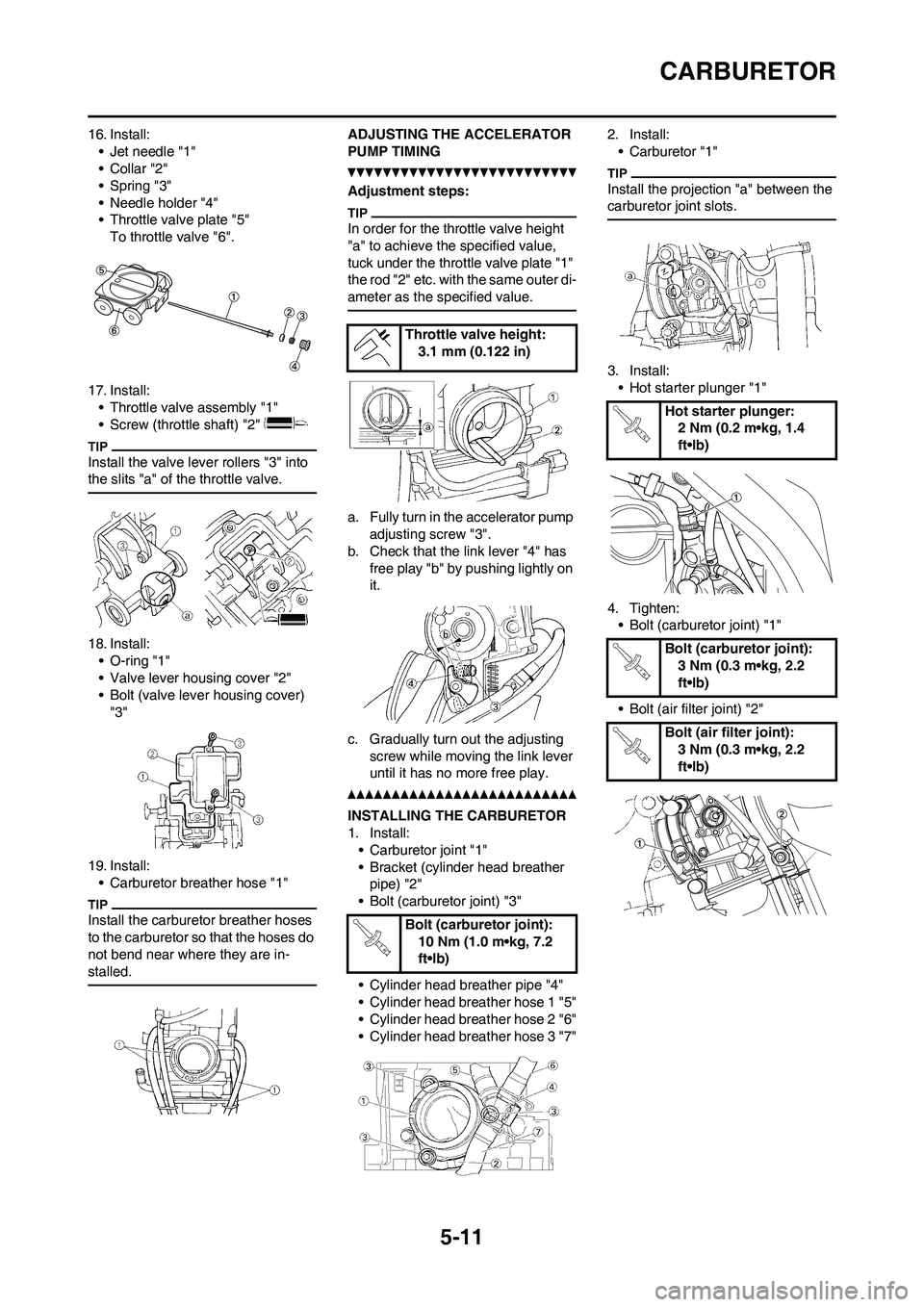
16. Install:
• Jet needle "1"
•Collar "2"
• Spring "3"
• Needle holder "4"
• Throttle valve plate "5"
To throttle valve "6".
17. Install:
• Throttle valve assembly "1"
• Screw (throttle shaft) "2"
Install the valve lever rollers "3" into
the slits "a" of the throttle valve.
18. Install:
• O-ring "1"
• Valve lever housing cover "2"
• Bolt (valve lever housing cover)
"3"
19. Install:
• Carburetor breather hose "1"
Install the carburetor breather hoses
to the carburetor so that the hoses do
not bend near where they are in-
stalled.
ADJUSTING THE ACCELERATOR
PUMP TIMING
Adjustment steps:
In order for the throttle valve height
"a" to achieve the specified value,
tuck under the throttle valve plate "1"
the rod "2" etc. with the same outer di-
ameter as the specified value.
a. Fully turn in the accelerator pump
adjusting screw "3".
b. Check that the link lever "4" has
free play "b" by pushing lightly on
it.
c. Gradually turn out the adjusting
screw while moving the link lever
until it has no more free play.
INSTALLING THE CARBURETOR
1. Install:
• Carburetor joint "1"
• Bracket (cylinder head breather
pipe) "2"
• Bolt (carburetor joint) "3"
• Cylinder head breather pipe "4"
• Cylinder head breather hose 1 "5"
• Cylinder head breather hose 2 "6"
• Cylinder head breather hose 3 "7"2. Install:
• Carburetor "1"
Install the projection "a" between the
carburetor joint slots.
3. Install:
• Hot starter plunger "1"
4. Tighten:
• Bolt (carburetor joint) "1"
• Bolt (air filter joint) "2"
Throttle valve height:
3.1 mm (0.122 in)
Bolt (carburetor joint):
10 Nm (1.0 m•kg, 7.2
ft•lb)
Hot starter plunger:
2 Nm (0.2 m•kg, 1.4
ft•lb)
Bolt (carburetor joint):
3 Nm (0.3 m•kg, 2.2
ft•lb)
Bolt (air filter joint):
3 Nm (0.3 m•kg, 2.2
ft•lb)
Page 116 of 230
5-13
AIR INDICTOIN SYSTEM
AIR INDICTOIN SYSTEM
REMOVING THE AIR INDUCTION SYSTEM
Order Part name Q'ty Remarks
1 Bracket 1
2 Air cut-off valve assembly 1
3Air induction hose (air cut-off valve - front of cyl-
inder head)1
4 Air induction pipe 1
5 Gasket 1
6Air induction hose (air cut-off valve - rear of cylin-
der head)1
7Air induction hose (air cut-off valve - air filter
case)1
Page 117 of 230

5-14
AIR INDICTOIN SYSTEM
CHECKING THE AIR INDUCTION
SYSTEM
1. Inspect:
• Air induction hose
Crack/damage→Replace.
• Air induction pipe
Crack/damage→Replace.
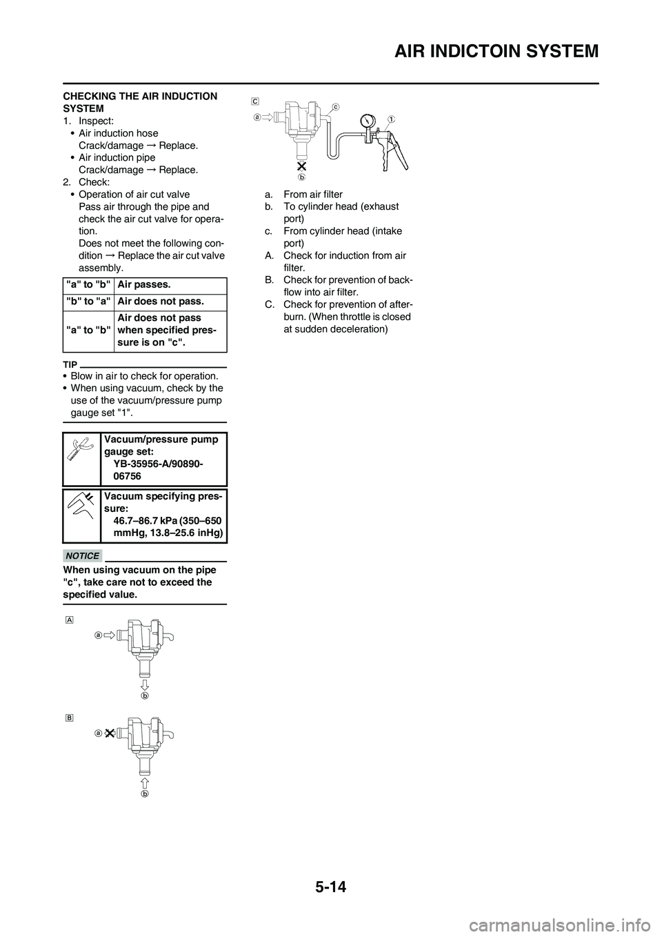
2. Check:
• Operation of air cut valve
Pass air through the pipe and
check the air cut valve for opera-
tion.
Does not meet the following con-
dition→Replace the air cut valve
assembly.
• Blow in air to check for operation.
• When using vacuum, check by the
use of the vacuum/pressure pump
gauge set "1".
When using vacuum on the pipe
"c", take care not to exceed the
specified value.
a. From air filter
b. To cylinder head (exhaust
port)
c. From cylinder head (intake
port)
A. Check for induction from air
filter.
B. Check for prevention of back-
flow into air filter.
C. Check for prevention of after-
burn. (When throttle is closed
at sudden deceleration) "a" to "b" Air passes.
"b" to "a" Air does not pass.
"a" to "b"Air does not pass
when specified pres-
sure is on "c".
Vacuum/pressure pump
gauge set:
YB-35956-A/90890-
06756
Vacuum specifying pres-
sure:
46.7–86.7 kPa (350–650
mmHg, 13.8–25.6 inHg)
Page 204 of 230
6-36
REAR SHOCK ABSORBER
REAR SHOCK ABSORBER
REMOVING THE REAR SHOCK ABSORBER
Order Part name Q'ty Remarks
Hold the machine by placing the suitable stand
under the engine.Refer to "HANDLING NOTE".
Seat and side cover Refer to "REMOVING THE SEAT, FUEL
TANK AND SIDE COVERS" section in the
CHAPTER 3.
Silencer Refer to "REMOVING THE EXHAUST PIPE
AND SILENCER" section in the CHAPTER 3.
Drain the coolant.Refer to "CHANGING THE COOLANT" sec-
tion in the CHAPTER 3.
Catch tank breather hose Disconnect at the catch tank side.
Catch tank hose Disconnect at the catch tank side.
Air induction hose (air cut-off valve-air filter case) Disconnect at the air filter case side.
Cylinder head breather hose Disconnect at the air filter case side.
BatteryRefer to "CHECKING AND CHARGING THE
BATTERY" section in the CHAPTER 3.
Disconnect the starter relay coupler.
Starter motor lead Disconnect at the starter relay side.
1 Locking tie 4
Page 205 of 230
6-37
REAR SHOCK ABSORBER
2 Taillight coupler 1
3 CDI unit coupler 3
4 Plastic band 1
5 Clamp (air filter joint) 1 Only loosening.
6Rear frame 1
7 Bolt (rear shock absorber-relay arm) 1 Hold the swingarm.
8 Bolt (rear shock absorber-frame) 1
9 Rear shock absorber 1
10 Locknut 1 Only loosening.
11 Adjuster 1 Only loosening.
12 Lower spring guide 1
13 Upper spring guide 1
14 Spring (rear shock absorber) 1
15 Bearing 2 Refer to removal section. Order Part name Q'ty Remarks
Page 208 of 230
6-40
REAR SHOCK ABSORBER
7. Tighten:
• Screw (air filter joint) "1"
8. Install:
• Plastic band
• Taillight coupler
• Locking tieScrew (air filter joint):
3 Nm (0.3 m•kg, 2.2
ft•lb)
Page:
< prev 1-8 9-16 17-24