Page 303 of 360

08 Maintenance and specifications
Hood and engine compartment
08
303 Opening and closing the hood
G031911
Pull the lever located under the left side of
the dash to release the hood lock. An infor-
mation symbol will illuminate when the
hood is open.
Lift the hood slightly. Press the release
control (located under the right front edge
of the hood) to the left, and lift the hood
WARNING
Check that the hood locks properly when
closed.
Engine compartment, overview
The appearance of the engine compartment
may vary depending on engine model.
Coolant expansion tank
Power steering fluid reservoir
Engine oil dipstick
Radiator
Filler cap for engine oil
Cover over brake fluid reservoir
Battery
Relay and fuse box
Washer fluid reservoir
Air cleaner
WARNING
The cooling fan may start or continue to
operate (for up to 6 minutes) after the engine
has been switched off.
WARNING
The ignition should always be completely
switched off before performing any opera-
tions in the engine compartment.
The distributor ignition system operates at
very high voltages. Special safety precau-
tions must be followed to prevent injury.
Always turn the ignition off when:
•Replacing distributor ignition compo-
nents e.g. plugs, coil, etc.
•Do not touch any part of the distributor
ignition system while the engine is run-
ning. This may result in unintended
movements and body injury.
Page 308 of 360

08 Maintenance and specifications
Replacing bulbs
08
308* Option/accessory, for more information, see Introduction.
Introduction
All bulb specifications are listed on page 314.
The following bulbs should only be replaced by
a trained and qualified Volvo service techni-
cian:
•Dome lighting, reading lights
•Glove compartment lighting
•Footwell lighting
•Turn signals in the door mirrors
•Approach lighting in the door mirrors
•Brake/fog/taillights
•Rear parking lights
•Active Bending Lights
•LED bulbs
NOTE
For information regarding any other bulbs
not mentioned in this section, please con-
tact your Volvo retailer or a trained and
authorized Volvo service technician.
WARNING
•Active Bending Lights* – due to the high
voltage used by these headlights, these
bulbs should only be replaced by a
trained and qualified Volvo service tech-
nician.
•Turn off the lights and remove the
remote key from the ignition before
changing any bulbs.
Headlight housing
WARNING
•The engine should not be running when
changing bulbs.
•If the engine has been running just prior
to replacing bulbs in the headlight hous-
ing, please keep in mind that compo-
nents in the engine compartment will be
hot.
The entire headlight housing must be lifted out
when replacing all front bulbs.
CAUTION
Never touch the glass of bulbs with your fin-
gers. Grease and oils from your fingers
vaporize in the heat and will leave a deposit
on the reflector, which will damage it.
Page 309 of 360

08 Maintenance and specifications
Replacing bulbs
08
��
309
NOTE
•Always switch off the ignition before
starting to replace a bulb.
•The optional Active Bending Light bulbs
contain trace amounts of mercury.
These bulbs should always be disposed
of by a trained and qualified Volvo serv-
ice technician.
Removing the headlight housing1. Switch off the ignition by briefly pressing
the START/STOP ENGINE button and
remove the remote key from the ignition
slot
1.
2. (Upper illustration under "Headlight hous-
ing")
Withdraw the headlight housing's lock-
ing pins.
Pull the headlight housing straight out.
CAUTION
When disconnecting the connector, pull on
the connector itself and not on the wiring.
3. (Lower illustration under "Headlight hous-
ing")
Unplug the wiring connector by holding
down the clip with your thumb.
Pull out the connector with the other
hand.
4. Lift out the housing and place it on a soft
surface to avoid scratching the lens.
5. Replace the defective bulb(s).
Reinserting the headlight housing
When reinserting the housing, be sure that the
long locking pin (to the left in the illustration) is
securely in place in both of its retaining clamps.
1. Plug in the connector until it clicks into
place.2. Reinstall the headlight housing and locking
pins. Check that they are correctly
inserted. The headlight housing must be
properly inserted and secured in place
before the lighting is switched on or the
remote key is inserted into the ignition slot.
3. Check that the lights function properly.
The headlight wiring must be connected and
the housing must be securely in place before
the ignition is switched on.
Removing the cover to access the
bulbs
1Does not apply to vehicles with the optional keyless drive.
Page 310 of 360

08 Maintenance and specifications
Replacing bulbs
08
310
NOTE
Before starting to replace a bulb, see
page 308.
1. Open the retaining clamps by pressing
them to the sides.
2. Pull the cover straight out.
Reinstall the cover in the reverse order.
Low beam, Halogen
1. Remove the headlight housing from the
vehicle (see page 308).
2. Remove the cover over the bulbs (see
page 309).3. Unplug the connector from the bulb.
4. Remove the bulb by pressing the holder
downward.
5. Press the new bulb into the socket until it
snaps into place. It can only be secured in
one position.
6. Put the cover back into position and rein-
stall the headlight housing.
High beam, Halogen
1. Remove the headlight housing from the
vehicle (see page 308).
2. Remove the cover over the bulbs (see
page 309).3. Remove the bulb by turning it counter-
clockwise and pulling it straight out.
4. Remove the connector from the bulb.
5. Press the new bulb into the socket and turn
it clockwise to put it in place. It can only be
secured in one position.
6. Reinsert the bulb holder into the headlight
housing.
7. Put the cover back into position and rein-
stall the headlight housing.
Extra high beam2
1. Remove the headlight housing from the
vehicle (see page 308).
2Models with optional Active Bending Lights only.
Page 311 of 360
.
3. Disconnect the wiring connector from the
bulb holder.
4. Remove the bulb holder from")
08 Maintenance and specifications
Replacing bulbs
08
��
311
2. Remove the cover over the bulbs (see
page 309).
3. Disconnect the wiring connector from the
bulb holder.
4. Remove the bulb holder from the headlight
housing by pulling it straight out.
5. Insert a new bulb in the holder until it snaps
in place. It can only be inserted in one way.
6. Press the bulb holder into position in the
headlight housing.
7. Reconnect the wiring connector to the bulb
holder.
8. Put the cover back into position and rein-
stall the headlight housing.
Turn signals
1. Remove the headlight housing from the
vehicle (see page 308).
2. Remove the bulb holder by turning it coun-
terclockwise and pulling it out of the head-
light housing.
3. Pull out the holder to access the bulb.
4. Remove the burned out bulb by pressing it
in slightly and turning it counterclockwise.
5. Press the new bulb into the holder and turn
it clockwise.
6. Reinsert the bulb holder into the headlight
housing and turn it clockwise.
7. Reinstall the headlight housing.
Side marker lights
NOTE
Before starting to replace a bulb, see
page 308.
1. Remove the headlight housing from the
vehicle (see page 308).
2. Remove the bulb holder by turning it coun-
terclockwise and pulling it out of the head-
light housing.
3. Pull out the burned out bulb and install a
new one. It can only be inserted in one
position.
4. Reinsert the bulb holder into the headlight
housing and turn it clockwise.
5. Reinstall the headlight housing.
Page 312 of 360
 can be reached from behind the
bumper
1. Remove the bulb h")
08 Maintenance and specifications
Replacing bulbs
08
312
Rear fog light
The rear fog light (located on the driver's side
of the vehicle) can be reached from behind the
bumper
1. Remove the bulb holder by turning it coun-
terclockwise.
2. Remove the burned out bulb by pressing it
in and turning it counterclockwise.
3. Insert a new bulb, press it in and turn it
clockwise.
4. Reinsert the bulb holder and turn it clock-
wise.
Location of taillight bulbs
Taillight lens, right side
Parking/side marker lights (LED)
Side reflector
Brake light
Backup light
Turn signal
Brake lights (LED)
NOTE
If an error message remains in the display
after a faulty bulb has been replaced, con-
tact an authorized Volvo workshop.
Brake lights and taillights
The brake lights and taillights are replaced from
inside the cargo area.
NOTE
Before starting to replace a bulb, see
page 308.
1. Open the panel.
2. Remove the bulb holder by turning it coun-
terclockwise.
3. Remove the burned out bulb by pressing it
in and turning it counterclockwise.
4. Insert a new bulb, press it in and turn it
clockwise.
5. Reinsert the bulb holder and turn it clock-
wise.
Page 313 of 360
08 Maintenance and specifications
Replacing bulbs
08
��
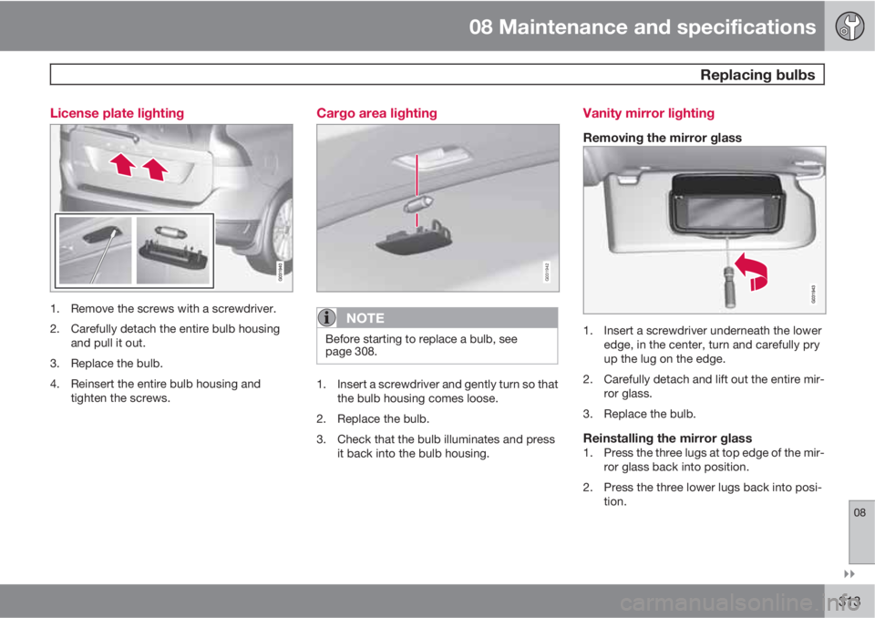
313 License plate lighting
1. Remove the screws with a screwdriver.
2. Carefully detach the entire bulb housing
and pull it out.
3. Replace the bulb.
4. Reinsert the entire bulb housing and
tighten the screws.
Cargo area lighting
G031942
NOTE
Before starting to replace a bulb, see
page 308.
1. Insert a screwdriver and gently turn so that
the bulb housing comes loose.
2. Replace the bulb.
3. Check that the bulb illuminates and press
it back into the bulb housing.
Vanity mirror lighting
Removing the mirror glass
1. Insert a screwdriver underneath the lower
edge, in the center, turn and carefully pry
up the lug on the edge.
2. Carefully detach and lift out the entire mir-
ror glass.
3. Replace the bulb.
Reinstalling the mirror glass1. Press the three lugs at top edge of the mir-
ror glass back into position.
2. Press the three lower lugs back into posi-
tion.
Page 314 of 360
08 Maintenance and specifications
Replacing bulbs
08
314
Bulb specifications
Lighting
functionWattageBulb
Active Bend-
ing Lights
(extra high
beam)65H9
Low beam
(halogen)55H7
High beam
(halogen)65H9
Front turn sig-
nals21PY21W
Cargo area
lighting,
license plate
lighting5Festoon
bulb
SV5.5
Vanity mirror1.2Festoon
bulb
SV5.5
Front side
marker lights5W3W
Glove com-
partment
lighting5Festoon
bulb
SV8.5
65H9
Low beam
(halogen)55H7
High beam
(halogen)65H9")