Page 106 of 388

03 Your driving environment
Compass*
03
106* Option/accessory, for more information, see Introduction.
Operation
Rearview mirror with compass.
The upper right-hand corner of the rearview
mirror has an integrated display that shows the
compass direction in which the front of the car
is pointing. Eight different directions are shown
with English abbreviations:
N (north), NE (north
east), E (east), SE (south east), S (south), SW(south west), W (west) and NW (north west).
The compass is activated automatically when
the car is started or in ignition position II, see
page 81. To deactivate/activate the compass -
press in the button on the underside of the mir-
ror using a paper clip for example.
CalibrationThe earth is divided into 15 magnetic zones.
The compass is set for the geographic area to
which the car was delivered. The compassshould be calibrated if the car is moved across
several magnetic zones.
1. Stop the car in a large open area free from
steel structures and high-voltage power
lines.
2. Start the car.
NOTE
For optimum calibration - switch off all elec-
trical equipment (climate control system,
wipers etc.) and make sure that all doors are
closed.
3. Hold the button on the underside of the
rearview mirror depressed
approx. 6 seconds (using a paper clip for
example) until the character
C is shown.
G030295
Magnetic zones.
4. Hold the button on the underside of the
rearview mirror depressed
approx. 3 seconds. The number of the cur-
rent magnetic zone is shown.
5. Press the button repeatedly until the
required magnetic zone (
1–15) is shown.
See the map of magnetic zones for the
compass.
6. Wait until the display resumes showing the
character
C.
7. Drive slowly in a circle at a speed of no
more than 10 km/h until a compass direc-
tion is shown in the display, indicating that
calibration is complete. Then drive a further
2 circles to fine-tune calibration.
8. Repeat the above procedure as necessary.
ProCarManuals.com
Page 186 of 388

04 Comfort and driving pleasure
City Safety™
04
186
When City Safety™ has prevented a collision
with a stationary object the car remains sta-
tionary for a maximum of 1.5 seconds. If the car
is braked for a vehicle in front that is moving,
then speed is reduced to the same speed as
that maintained by the vehicle in front.
On a car with manual gearbox the engine stops
when City Safety™ has stopped the car, unless
the driver manages to depress the clutch pedal
beforehand.
NOTE
•Keep the windscreen surface in front of
the laser sensor free from ice, snow and
dirt (see the illustration for sensor loca-
tion, page 184).
•Do not affix or mount anything on the
windscreen in front of the laser sensor
•Remove ice and snow from the bonnet
- snow and ice must not exceed a height
of 5 cm.
Fault tracing and action
If the message Windscreen Sensors
blocked is shown on the instrument panel dis-
play, it indicates that the laser sensor is
blocked and cannot detect vehicles in front of
the car. This means that City Safety™ is not
operational.The
Windscreen Sensors blocked message
is not shown for all situations in which the laser
sensor is blocked. The driver must therefore be
diligent about keeping the windscreen and
area in front of the laser sensor clean.
The following table presents possible causes
for the message being shown, along with sug-
gestions for appropriate action.
CauseAction
The windscreen sur-
face in front of the
laser sensor is dirty
or covered with ice
or snow.Clean the wind-
screen surface in
front of the sensor
from dirt, ice and
snow.
The laser sensor
field of vision is
blocked.Remove the block-
ing object.
IMPORTANT
If there are cracks, scratches or stone chips
in the windscreen in front of either of the
laser sensor's "windows" and they cover a
surface of approx. 0.5 x 3.0 mm (or larger),
then a workshop must be contacted for
repair or replacement of the windscreen
(see the illustration for sensor location, page
184) - an authorised Volvo workshop is rec-
ommended.
Failure to take action may result in reduced
performance for City Safety™.
To avoid the risk of reducing City Safety™
performance the following also applies:
•The same type or a Volvo-approved
windscreen must be fitted during
replacement
•The same type or Volvo-approved
windscreen wipers must be fitted during
replacement.
Laser sensor
The City Safety™ function includes a sensor
which transmits laser light. Contact a qualified
workshop in the event of a fault or if the laser
sensor needs servicing - an authorised Volvo
workshop is recommended.
ProCarManuals.com
Page 319 of 388
08 Maintenance and service
Wiper blades and washer fluid
08
��
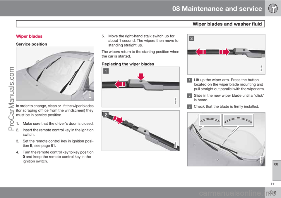
319 Wiper blades
Service position
In order to change, clean or lift the wiper blades
(for scraping off ice from the windscreen) they
must be in service position.
1. Make sure that the driver's door is closed.
2. Insert the remote control key in the ignition
switch.
3. Set the remote control key in ignition posi-
tion II, see page 81.
4. Turn the remote control key to key position
0 and keep the remote control key in the
ignition switch.5. Move the right-hand stalk switch up for
about 1 second. The wipers then move to
standing straight up.
The wipers return to the starting position when
the car is started.
Replacing the wiper blades
Lift up the wiper arm. Press the button
located on the wiper blade mounting and
pull straight out parallel with the wiper arm.
Slide in the new wiper blade until a "click"
is heard.
Check that the blade is firmly installed.
G021763
ProCarManuals.com
Page 327 of 388

08 Maintenance and service
Fuses
08
��
* Option/accessory, for more information, see Introduction.327
General fuses, engine compartmentOn the inside of the cover there are tweezers
that facilitate the procedure for the removal
and fitting of fuses.
Positions (see preceding illustration)Engine compartment, upper
Engine compartment, front
Engine compartment, lower
These fuses are all located in the engine com-
partment box. The fuses in (C) are located
under (A).
•Fuses 1-7 and 42-44 are of the "Midi Fuse"
type and must only be replaced by a work-
shop
1.
•Fuses 8-15 and 34 are of the "JCASE" type
and should be replaced by a workshop1.
•Fuses 16-33 and 35-41 are of the "Mini
Fuse" type.
FunctionA
Primary fuse for the cen-
tral electronic module
(CEM) with fuse box B
under the glovebox
A
50
Primary fuse for the cen-
tral electronic module
(CEM) with fuse box B
under the glovebox50
Primary fuse for central
electrical unit in cargo
area
A
60
Primary fuse for central
electrical unit in passenger
compartment with fuse
box A under the glove-
box
A
60
Primary fuse for central
electrical unit in passenger
compartment with fuse
box A under the glove-
box
A
60
--
FunctionA
PTC element air pre-
heater*A100
Headlamp washers*20
Windscreen wipers30
Parking heater*25
Ventilation fanA40
--
ABS pump40
ABS valves20
--
Headlamp levelling*
(Xenon, Active Xenon)10
Primary fuse for the cen-
tral electronic module
(CEM) with fuse box B
under the glovebox20
ABS5
1An authorised Volvo workshop is recommended.
ProCarManuals.com
Page 386 of 388
10 Alphabetical Index
10
386
Windscreen wipers.................................... 98
rain sensor............................................ 98
Winter driving........................................... 267
Winter tyres.............................................. 290
Wiper blades............................................ 319
changing............................................. 319
cleaning.............................................. 320
service position................................... 319
Wipers and washing.................................. 98
ProCarManuals.com