2011 VOLKSWAGEN TRANSPORTER information
[x] Cancel search: informationPage 198 of 486
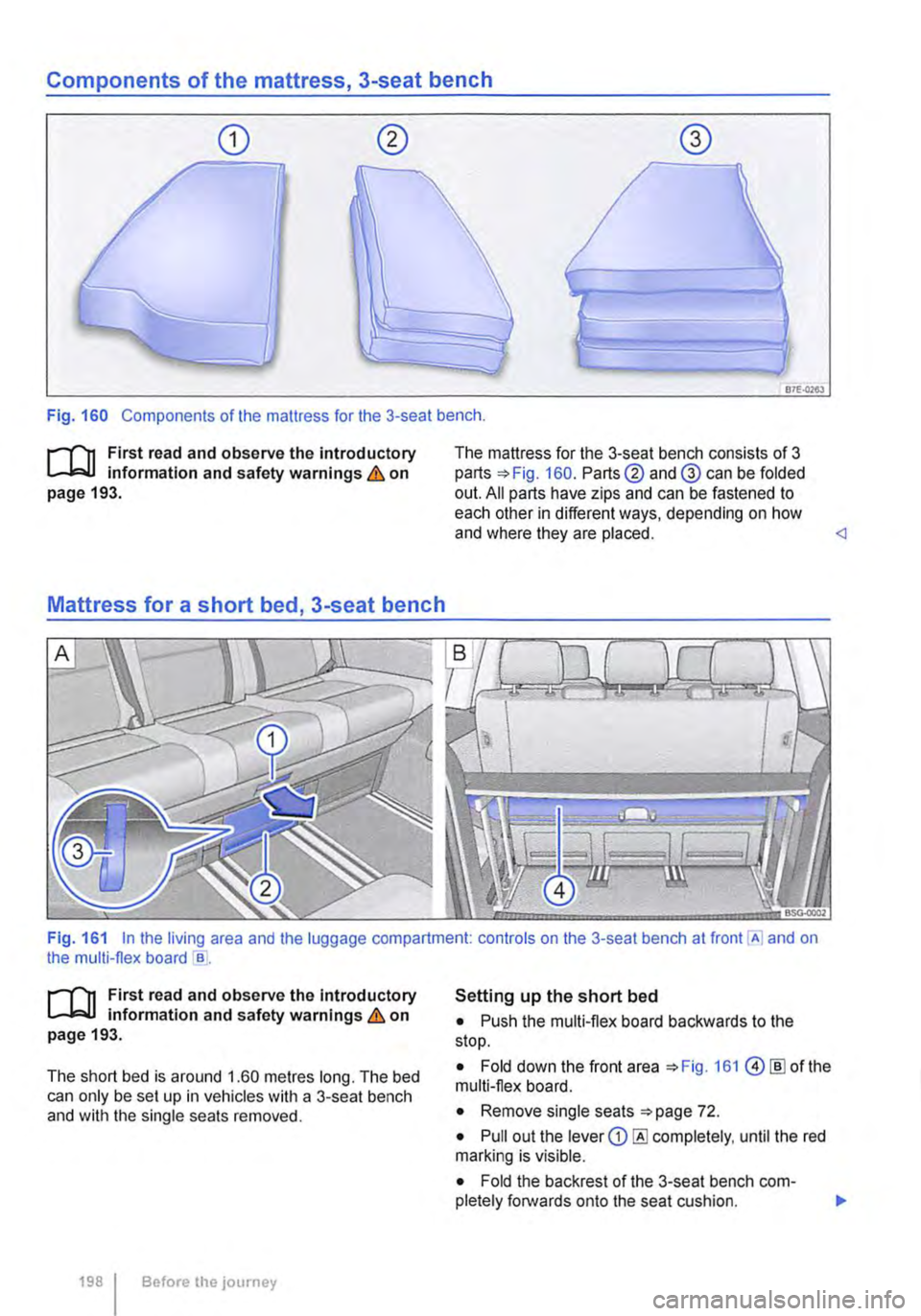
Components of the mattress, 3-seat bench
87E-0263
Fig. 160 Components of the mattress for the 3-seat bench .
.--m First read and observe the introductory l.-l=.U information and safety warnings & on page 193.
Mattress for a short bed, 3-seat bench
The mattress for the 3-seat bench consists of 3 parts 160. Parts@ and@ can be folded out. All parts have zips and can be fastened to each other in different ways, depending on how and where they are placed.
.--m First read and observe the Introductory l.-l=.U information and safety warnings & on page 193.
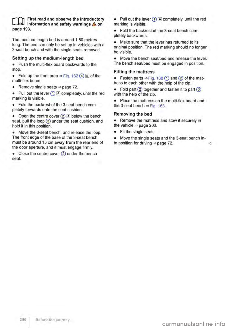
The short bed is around 1.60 metres long. The bed can only be set up in vehicles with a 3-seat bench and with the single seats removed.
198 I Before the journey
Setting up the short bed
• Push the multi-flex board backwards to the stop.
• Fold down the front area 161 @[ID of the multi-flex board.
• Remove single seats 72.
• Pull out the lever CD completely, until the red marking is visible.
• Fold the backrest of the 3-seat bench com-pletely forwards onto the seat cushion. 11>
Page 200 of 486
,...-m First read and observe the Introductory L--W.I Information and safety warnings & on page 193.
The medium-length bed is around 1.80 metres long. The bed can only be set up In vehicles with a 3-seat bench and with the single seats removed.
Setting up the medium-length bed
• Push the multi-flex board backwards to the stop.
• Fold up the front area 162 @!ID of the multi-flex board.
• Remove single seats 72.
• Pull out the lever completely, until the red marking is visible.
• Fold the backrest of the 3-seat bench com-pletely forwards onto the seat cushion.
• Open the centre below the bench seat, pull the loop @ under the seat cushion, and hold it in this position.
• Move the 3-seat bench, and release the loop. The front edge of the base of the 3-seat bench must be around 15 cm away from the rear end of the door aperture, and it must engage firmly.
• Close the centre cover® under the bench seat.
200 Before tho JOurney
• Pull out the lever completely, until the red marking is visible.
• Fold the backrest of the 3-seat bench com-pletely backwards.
• Make sure that the lever has returned to its original position. The red marking should no longer be visible.
• Move the bench seaUbed and release the lever. The bench seaUbed must be engaged in position.
Fitting the mattress
• Fasten parts 160 CD and® of the mat-tress to each other with the help of the zip.
• Fold part® together and fasten it to part@ with the help of the zip.
• Place the mattress on the multi-flex board and the 3-seat bench 163.
Removing the bed
• Remove the mattress and stow it securely in the vehicle 203.
• Fit the single seats.
• Move the single seats and the 3-seat bench in-to position for driving 72.
Page 201 of 486
Mattress for a long bed, 3-seat bench
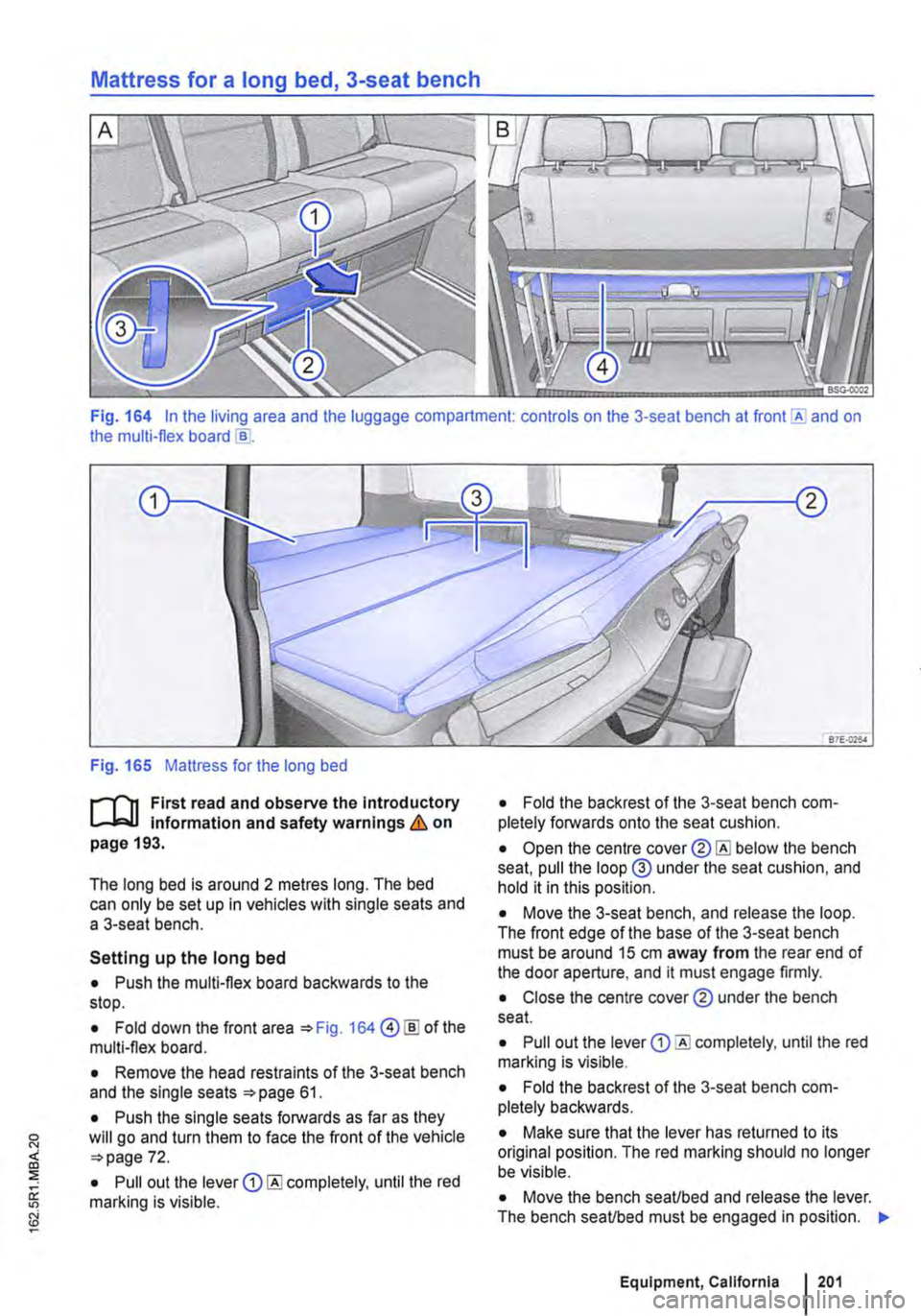
Fig. 164 In the living area and the luggage compartment: controls on the 3-seat bench at and on the multi-flex board
Fig. 165 Mattress for the long bed
r-1'lt First read and observe the Introductory L-J,:::..U Information and safety warnings & on page 193.
The long bed is around 2 metres long. The bed can only be set up in vehicles with single seats and a 3-seat bench.
Setting up the long bed
• Push the multi-flex board backwards to the stop.
• Fold down the front area 164@ [ID of the multi-flex board.
• Remove the head restraints of the 3-seat bench and the single seats 61.
• Push the single seats forwards as far as they will go and turn them to face the front of the vehicle 72.
• Pull out the lever completely, until the red marking is visible.
• Fold the backrest of the 3-seat bench com-pletely forwards onto the seat cushion.
• Open the centre below the bench seat, pull the loop@ under the seat cushion, and hold it in this position.
• Move the 3-seat bench, and release the loop. The front edge of the base of the 3-seat bench must be around 15 cm away from the rear end of the door aperture, and it must engage firmly.
• Close the centre cover® under the bench seat.
• Pull out the lever completely, until the red marking is visible.
• Fold the backrest of the 3-seat bench com-pletely backwards.
• Make sure that the lever has returned to its original position. The red marking should no longer be visible.
• Move the bench seaUbed and release the lever. The bench seaUbed must be engaged in position. "'
Equipment, California 201
Page 203 of 486
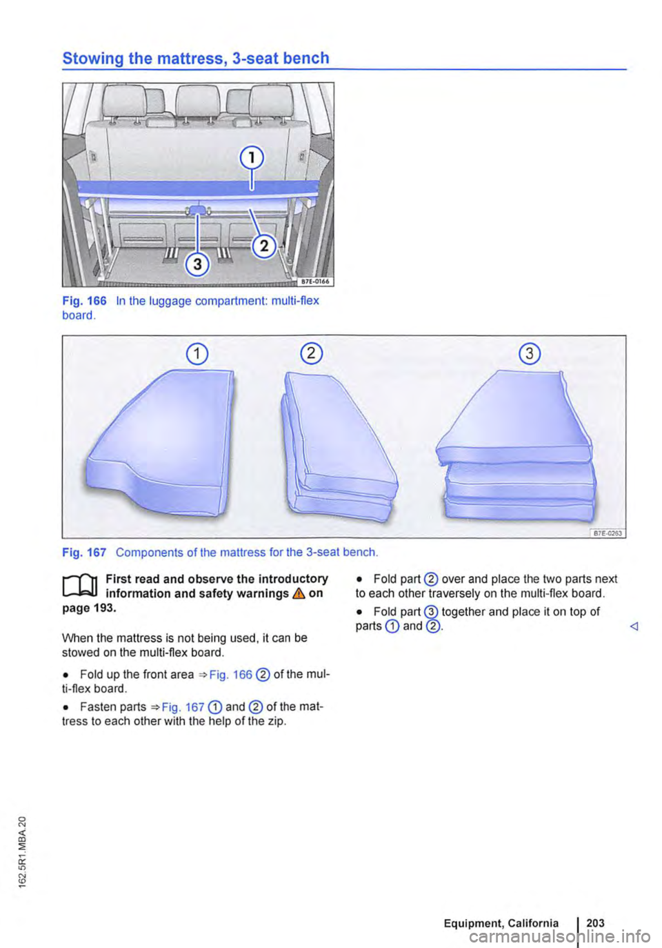
Fig. 166 In the luggage compartment: multi-flex board.
Fig. 167 Components of the mattress for the 3-seat bench.
r--f"'n First read and observe the introductory L-W.I information and safety warnings & on page 193.
When the mattress is not being used, it can be stowed on the multi-flex board.
• Fold up the front area 166 @of the mul-ti-flex board.
• Fasten parts 167 CD and@ of the mat-tress to each other with the help of the zip.
• Fold part@ over and place the two parts next to each other traversely on the multi-flex board.
• Fold part@ together and place it on top of parts CD and @.
Page 204 of 486
Central control panel, California
COl Introduction
This chapter contains information on the following subjects:
Controls . . . . . . . . . . . . . . . . . . . . . . . . . . . . . . . 204
Display . . . . . . . . . . . . . . . . . . . . • . . . . 205
Menu structure . . . . . . . . . . . . . . . . . . . . . . . . . . 206 Programming the wake up time . . . . . . . • . . . . 207
Programming the countdown timer . . . . . . . . . 207
The central control panel is the "control and infor-mation centre" for the camping equipment. The central control panel can be used to open and con-trol the following displays and functions:
• Opening and closing the electric pop-up roof 221
• Displays showing the ambient temperature, clock and charging status of the additional batter-ies 205
Controls
• Switching the refrigerator box on and off or set-ting the temperature =>page 241
• Status display and control of supplementary heater 251
• Programming countdown timer 207
• Programming the wake up time 207
• Setting the clock
Additional information:
• Cleaning the central control panel 254
• Rectifying faults on the camping equipment 254
q Donnerstag g
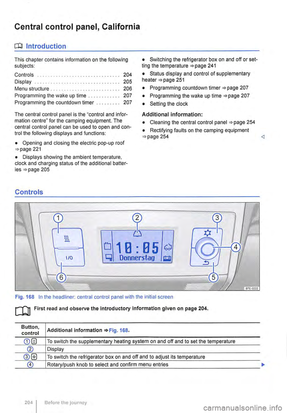
Fig. 168 In the headliner: central control panel with the initial screen
ro First read and observe the Introductory Information given on page 204.
Button, control
204 I
Additional Information 168.
To switch the supplementary heating system on and off and to set the temperature
Display
To switch the refrigerator box on and off and to adjust its temperature
Rotary/push knob to select and confirm menu entries
Before the journey
Page 205 of 486
Button, control
Display
®
Additional information =>Fig. 168.
To return to initial screen or cancel a setting without saving it
To completely switch off all functions which were activated using the central control panel, e.g. supplementary heating system, refrigerator box, and wake-up time <1
1 9.5 ° c
Fr f."l11 :28
0
Pj
3
0 117H-01S9
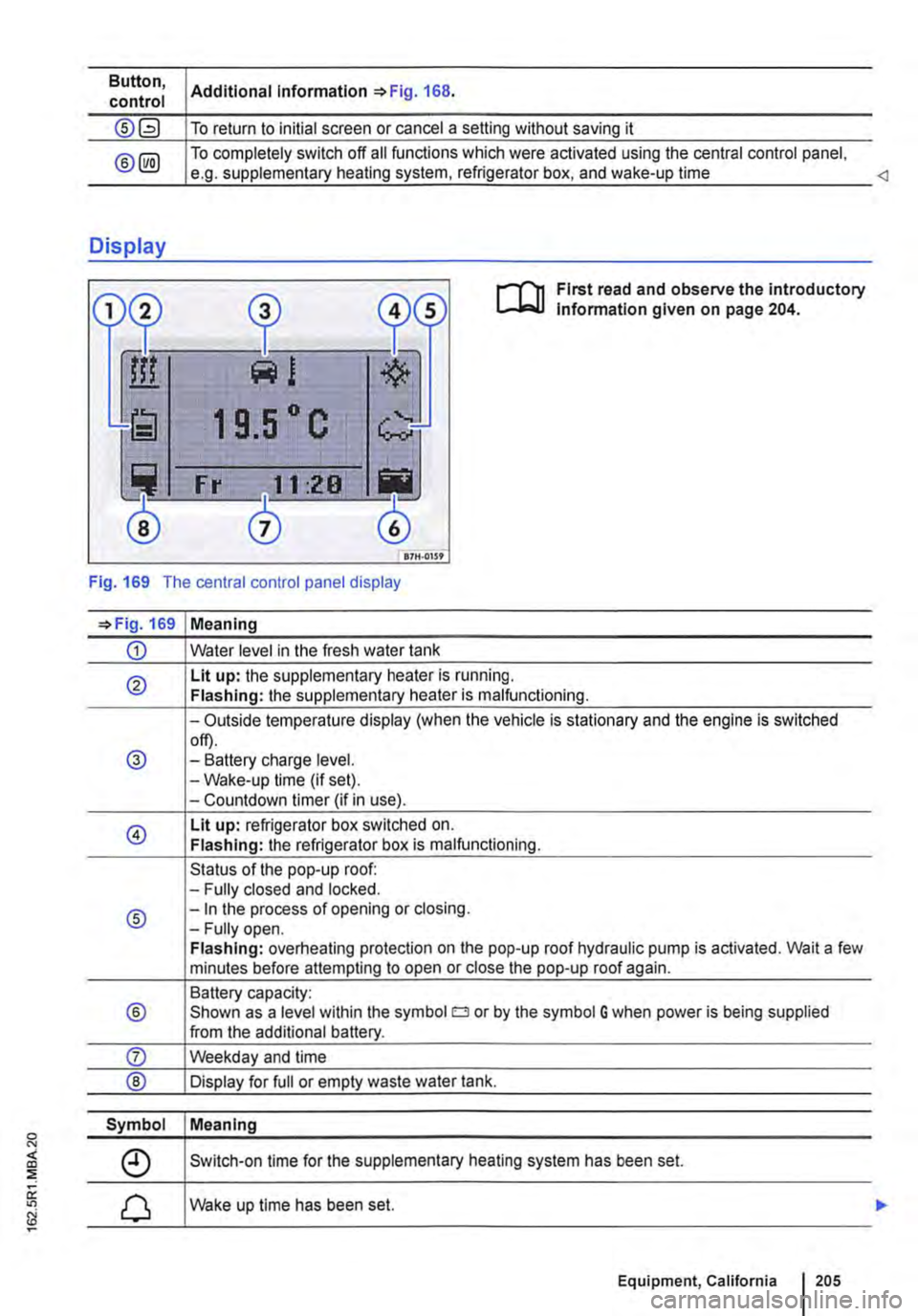
First read and observe the introductory lnfonmation given on page 204.
Fig. 169 The central control panel display
=>Fig. 169 Meaning
CD Water level in the fresh water tank
® Lit up: the supplementary heater is running. Flashing: the supplementary heater is malfunctioning.
-Outside temperature display (when the vehicle is stationary and the engine is switched
@ off). -Battery charge level. -Wake-up time (if set). -Countdown timer (if in use).
@ Lit up: refrigerator box switched on. Flashing: the refrigerator box is malfunctioning.
Status of the pop-up roof: -Fully closed and locked.
® -In the process of opening or closing. -Fully open. Flashing: overheating protection on the pop-up roof hydraulic pump is activated. Wait a few minutes before attempting to open or close the pop-up roof again.
Battery capacity:
® Shown as a level within the symbol o or by the symbol G when power is being supplied from the additional battery.
Symbol Meaning
Switch-on time for the supplementary heating system has been set.
Wake up time has been set.
Equipment, California 1205
Page 206 of 486
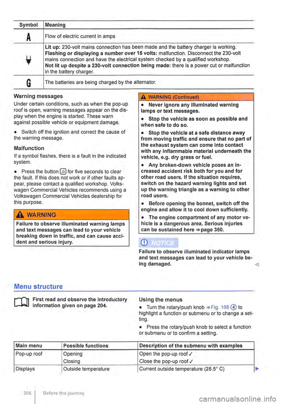
Symbol Meaning
A Flow of electric current in amps
Lit up: 230-volt mains connection has been made and the battery charger is working. Flashing or displaying a number over 15 volts: malfunction. Disconnect the 230-volt mains connection and have the electrical system checked by a qualified workshop. Not lit up despite a 230-volt connection being made: there is a power cut or malfunction in the battery charger.
G The batteries are being charged by the alternator.
Warning messages
Under certain conditions, such as when the pop-up roof is open, warning messages appear on the dis-play when the engine is started. These warn against possible vehicle or equipment damage.
• Switch off the ignition and correct the cause of the warning message.
Malfunction
If a symbol flashes, there is a fault in the indicated system.
• Press the button G?) for five seconds to clear the fault. If this does not work or if other faults ap-pear, please contact a qualified workshop. Volks-wagen Commercial Vehicles recommends using a Volkswagen Commercial Vehicles dealership for this purpose.
A WARNING
Failure to observe illuminated warning lamps and text messages can lead to your vehicle breaking down in traffic, and can cause acci-dent and serious injury.
A WARNING (Continued)
• Never Ignore any Illuminated warning lamps or text messages.
• Stop the vehicle as soon as possible and when safe to do so.
• Stop the vehicle at a safe distance away from moving traffic and ensure that no part of the exhaust system can come Into contact with any Inflammable material underneath the vehicle, e.g. dry grass or fuel.
• Any broken-down vehicle poses an In-creased accident risk both for you and for other road users. If the situation requires, switch on the hazard warning lights and set up the warning triangle as a warning to other road users.
• Before opening the bonnet, switch off the engine and allow it to cool down sufficiently.
• The engine compartment of any motor ve-hicle is a dangerous area. Serious injuries can be sustained here 350.
CD
Failure to observe illuminated indicator lamps and text messages can lead to your vehicle be-ing damaged.
J'"'""'('n First read and observe the introductory L-J,:.IJ information given on page 204.
Main menu Possible functions
Pop-up roof Opening
Closing
Displays Outside temperature
206 Before the journey
Using the menus
• Turn the rotary/push knob 168@ to highlight a function or submenu or to change a set-ting.
• Press the rotary/push knob to select a function or submenu or to confirm a setting.
Description of the submenu with examples
Open the pop-up roof .,1
Close the pop-up roof .,t
Current outside temperature (28.SO C) ...
Page 207 of 486
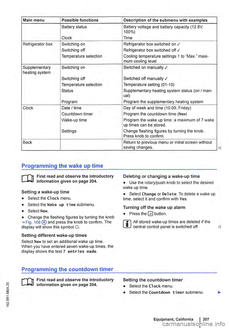
Main menu Possible functions
Battery status
Clock
Refrigerator box Switching on
Switching off
Temperature selection
Supplementary Switching on heating system
Switching off
Temperature selection
Status
Program
Clock Date I time
Countdown timer
Wake-up time
Settings
Back
Programming the wake up time
r--f"'n First read and observe the introductory L-lo::.U information given on page 204.
Setting a wake-up time
• Select the Clock menu.
• Select the Wake up time submenu.
• Select New.
• Change the flashing figures by turning the knob 168@ and press the knob to confirm. The display will show this symbol 0.
Setting different wake-up times
Select New to set an additional wake up time. When you have entered seven wake-up times, the display shows the text 7 entries made.
Programming the countdown timer
r--f"'n First read and observe the introductory L-lo::.U information given on page 204.
Description of the submenu with examples
Battery voltage and battery capacity (12.8V, 100%)
Time
Refrigerator box switched on .t
Refrigerator box switched off ./
Cooling temperature settings 1 to "Max." maxi-mum cooling level
Switched on manually .;
Switched off manually .;
Temperature setting (01-10)
Supplementary heating system status (on I man-ual)
Program the supplementary heating system
Day of week and time (10:09. Friday)
Program the countdown time (New)
Program the wake up time: a maximum of 7 wake up times can be stored.
Change flashing figures by turning the knob. Press knob to confirm.
Return to previous menu or initial screen without saving changes.
Deleting or changing a wake-up time
• Use the rotary/push knob to select the desired wake up time.
• Select Change or Del et e. To delete a wake up time, select it and confirm with Yes.
Turning off the wake up alarm
• Press button.
r::l All stored wake-up times are deleted if the L!J central control panel is switched off.
Setting the countdown timer
• Select the Clock menu.
• Select the Countdown timer submenu.
Equipment, California I 207