2011 VOLKSWAGEN TRANSPORTER coolant
[x] Cancel search: coolantPage 333 of 486
Controls
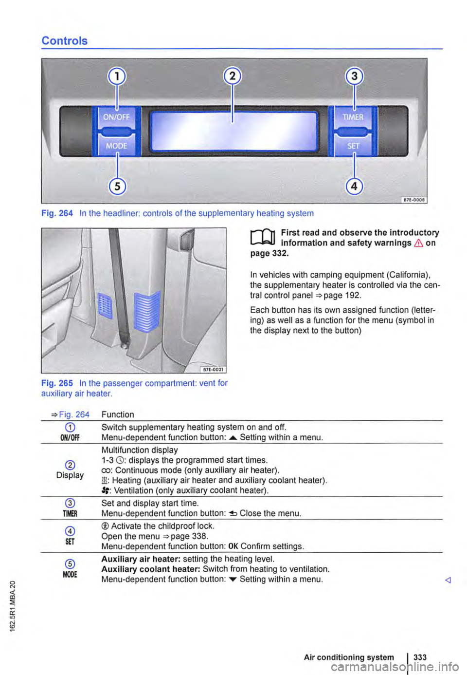
Fig. 264 In the headliner: controls of the supplementary heating system
I""""T'n First read and observe the introductory l.-..1=.1.1 infonmatlon and safety warnings & on page 332.
In vehicles with camping equipment (California), the supplementary heater is controlled via the cen-tral control panel 192.
Each button has its own assigned function (letter-ing) as well as a function for the menu (symbol in the display next to the button)
Fig. 265 In the passenger compartment: vent for auxiliary air heater.
264
G) ON/Off
® Display
@ TMR
@ S£T
® MODE
Function
Switch supplementary heating system on and off. Menu-dependent function button: ......_ Setting within a menu.
Multifunction display 1-3 (3): displays the programmed start times. ro: Continuous mode (only auxiliary air heater). Jli: Heating (auxiliary air heater and auxiliary coolant heater). Ventilation (only auxiliary coolant heater).
Set and display start time. Menu-dependent function button: Close the menu.
®Activate the child proof lock. Open the menu 338. Menu-dependent function button: OK Confirm settings.
Auxiliary air heater: setting the heating level. Auxiliary coolant heater: Switch from heating to ventilation. Menu-dependent function button: ...,. Setting within a menu.
Air conditioning system I 333
Page 334 of 486
Switching the supplementary heating system on and off
r-Y'n First read and observe the introductory L-J.:.I.I information and safety warnings & on page 332.
In vehicles with camping equipment (California), the supplementary heater is controlled via the cen-tral control panel =>page 192.
Switching on the supplementary heating sys-tem:
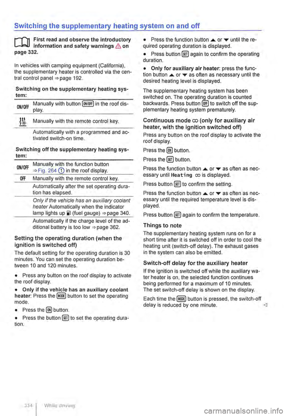
Manually with button [011/0IF) in the roof dis-ON/OFF play.
l/i Manually with the remote control key.
Automatically with a programmed and ac-tivated switch-on time.
Switching off the supplementary heating sys-tem:
ON/OFF Manually with the function button =>Fig. 264 CD in the roof display.
Off Manually with the remote control key.
Automatically after the set operating dura-tion has elapsed.
Only if the vehicle has an auxiliary coolant heater Automatically when the indicator lamp lights (fuel gauge) =>page 340.
Automatically if the charge level of the ad-ditional battery is too low =>page 362.
Setting the operating duration (when the ignition is switched off)
The default setting for the operating duration is 30 minutes. You can set the operating duration be-tween 10 and 120 minutes.
• Press any button on the roof display to activate the roof display.
• Only if the vehicle has an auxiliary coolant heater: Press the button to set the operating mode.
• Press the@ button.
• Press the button@) to set the operating dura-tion.
334 I While driv1ng
• Press the function button ....,. or T until the re-quired operating duration is displayed.
• Press button@) again to confirm the operating duration.
• Only for auxiliary air heater: press the func-tion button ....,. or ... as often as necessary until the desired heating level is displayed.
The supplementary heating system has been switched on. The operatin_lLduration is counted backwards. Press to switch off the sup-plementary heating system prematurely.
Continuous mode eo (only for auxiliary air heater, with the ignition switched off)
Press any button on the roof display to activate the roof display.
Press the@) button.
Press the @) button.
Press the function button ....,. or ... as often as nec-essary until Heating eo is displayed.
Press button @)to confirm the setting.
Press the function button ....,. or T as often as nec-essary until the required temperature level is dis-played.
Press button @)again to confirm the temperature.
Things to note
The supplementary heating system runs on for a short time after it is switched off in order to cool the heating unit (switch-off delay). The exhaust gases in the system can also be emitted.
Switch-off delay for the auxiliary heater
If the ignition is switched off while the auxiliary wa-ter heater is on, the selected function continues being performed for a maximum of 10 minutes. The set switch-off delay is shown on the display.
Each time button is pressed, the switch-off delay is reduced by one minute.
Page 335 of 486
Remote control
B
BSG·OOS3
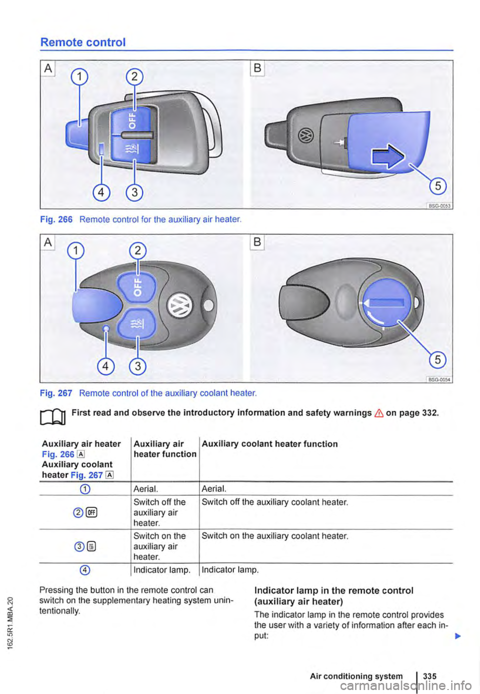
Fig. 266 Remote control for the auxiliary air heater.
A
BSG-0054
Fig. 267 Remote control of the auxiliary coolant heater.
ru First read and observe the introductory Information and safety warnings & on page 332.
Auxiliary air heater Auxiliary air Auxiliary coolant heater function Fig. heater function Auxiliary coolant heater Fig. 267
CD Aerial. Aerial.
Switch off the Switch off the auxiliary coolant heater.
0@) auxiliary air heater.
Switch on the Switch on the auxiliary coolant heater.
0@ auxiliary air heater.
@) Indicator lamp. Indicator lamp.
Pressing the button in the remote control can switch on the supplementary heating system unin-tentionally.
Indicator lamp in the remote control (auxiliary air heater)
The indicator lamp in the remote control provides the user with a variety of information after each in-put: 1>-
Air conditioning system 335
Page 336 of 486
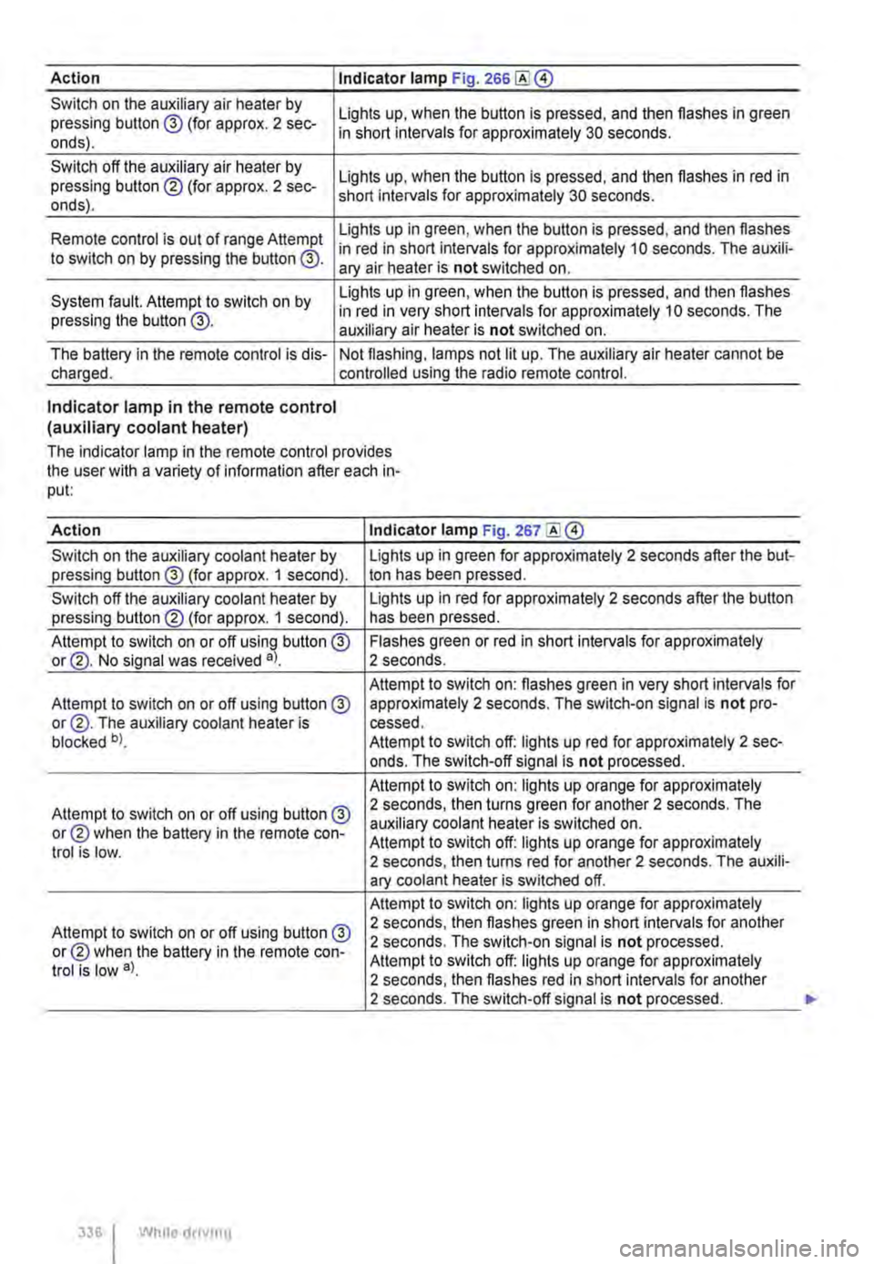
Action I Indicator lamp Fig. 266
Switch on the auxiliary air heater by pressing button @ (for approx. 2 sec-onds).
Switch off the auxiliary air heater by pressing button ® (for approx. 2 sec-onds).
Lights up, when the button is pressed, and then flashes in green in short intervals for approximately 30 seconds.
Lights up, when the button is pressed, and then flashes in red in short intervals for approximately 30 seconds.
Lights up in green, when the button is pressed, and then flashes Remote control is out of range Attempt in red in short intervals for approximately 10 seconds. The auxili-to switch on by pressing the button @. ary air heater is not switched on.
System fault. Attempt to switch on by pressing the button @.
Lights up in green, when the button is pressed, and then flashes in red in very short intervals for approximately 10 seconds. The auxiliary air heater is not switched on.
The battery in the remote control is dis-charged. Not flashing, lamps not lit up. The auxiliary air heater cannot be controlled using the radio remote control.
Indicator lamp in the remote control (auxiliary coolant heater)
The indicator lamp in the remote control provides the user with a variety of information after each in-put:
Action Indicator lamp Fig. 267
Switch on the auxiliary coolant heater by Lights up in green for approximately 2 seconds after the but-pressing button@ (for approx. 1 second). ton has been pressed.
Switch off the auxiliary coolant heater by Lights up in red for approximately 2 seconds after the button pressing button® (for approx. 1 second). has been pressed.
Attempt to switch on or off using button @ Flashes green or red in short intervals for approximately or@. No signal was received a). 2 seconds.
Attempt to switch on: flashes green in very short intervals for Attempt to switch on or off using button@ approximately 2 seconds. The switch-on signal is not pro-or@. The auxiliary coolant heater is cessed. blocked b). Attempt to switch off: lights up red for approximately 2 sec-onds. The switch-off signal is not processed.
Attempt to switch on: lights up orange for approximately
Attempt to switch on or off using button@ 2 seconds, then turns green for another 2 seconds. The
or® when the battery in the remote con-auxiliary coolant heater is switched on. Attempt to switch off: lights up orange for approximately trot is low. 2 seconds, then turns red for another 2 seconds. The auxili-ary coolant heater is switched off.
Attempt to switch on: lights up orange for approximately
Attempt to switch on or off using button @ 2 seconds, then flashes green in short intervals for another
or® when the battery in the remote con-2 seconds. The switch-on signal is not processed.
trot is low a). Attempt to switch off: lights up orange for approximately 2 seconds, then flashes red in short intervals for another 2 seconds. The switch-off signal is not processed.
336 I While droving
Page 337 of 486
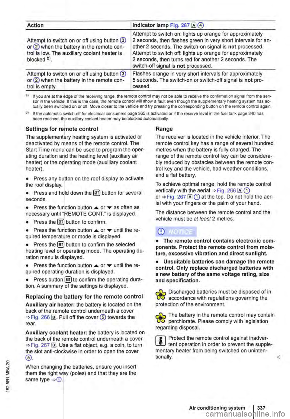
Action Indicator lamp Fig. 267
Attempt to switch on: lights up orange for approximately Attempt to switch on or off using button @ or@ when the battery in the remote con-trol is low. The auxiliary coolant heater is blocked bl.
2 seconds, then flashes green in very short intervals for an-other 2 seconds. The switch-on signal is not processed. Attempt to switch off: lights up orange for approximately 2 seconds, then turns red for another 2 seconds. The switch-off signal is not processed.
Attempt to switch on or off using button @ or@ when the battery in the remote con-trol is empty.
Flashes orange in very short intervals for approximately 5 seconds. The switch-on or switch-off signal is not pro-cessed.
•> If you are at the edge of the receiving range, the remote control may not be able to receive the confirmation signal from the sen-sor in the vehicle. If this is the case, the remote control will show a fault even though the supplementary heating system has ac-tually been switched on or off. Move closer to the vehicle and try pressing the corresponding button on the remote control again.
b) If the automatic switch-off for electrical consumers page 365 is activated or if the reserve level in lhe fuel tank page 340 has been reached, the auxiliary coolant heater may be blocked automatically.
Settings for remote control
The supplementary heating system is activated or deactivated by means of the remote control. The Start Time menu can be used to program the oper-ating duration and the heating level (auxiliary air heater) or the operating mode (auxiliary coolant heater).
• Press any button on the roof display to activate the roof display.
• Press and hold down the (ill) button for several seconds.
• Press the function button ...... or ,... as often as necessary until "REMOTE CONT." is displayed.
• Press the (ill) button to confirm.
• Press the function button ...... or ,... until the re-quired temperature or mode is displayed.
• Press the (ill) button to confirm the selected heating level or operating mode. The operating du-ration menu is displayed.
• Press the function button ...... or ,... until the re-quired operating duration is displayed.
• Press button @)to confirm the operating dura-tion. A summary of the settings is displayed.
Replacing the battery for the remote control
Auxiliary air heater: the battery is located on the back of the remote control underneath a cover 266 [ID. Pull off the cover® towards the rear.
Auxiliary coolant heater: the battery is located on the back of the remote control underneath a cover 267 [ID. Use a flat object, e.g. a coin, to turn the slot anti-clockwise in order to open the cover
®-
When changing the batteries, ensure you insert them the right way (poles) and that they are the same type
Range
The receiver is located in the vehicle interior. The remote control key has a range of several hundred metres when the battery is fully charged. The range of the remote control key can be considera-bly reduced by obstacles between the remote con-trol key and the vehicle, bad weather conditions, and a flat battery.
To achieve optimal range, hold the remote control vertically with the aerial 266 or 267 at the top. Do not hold the aer-ial with your fingers or the palm of your hand.
The distance between the remote control and the vehicle must be at least 2 metres.
CD
• The remote control contains electronic com-ponents. Protect the remote control from mois-ture, excessive vibration and direct sunlight.
• Unsuitable batteries can damage the remote control. Only replace discharged batteries with a new battery of the same voltage rating, size and specification.
Discharged batteries must be disposed of in W accordance with regulations governing the protection of the environment.
The battery in the remote control may contain W perchlorate. Please comply with legislation regarding disposal.
m Protect the remote control against inadver-L!.J tent operation in order to prevent the supple-mentary heater from being switched on uninten-
Air conditioning system I 337
Page 343 of 486
Capacities
r--('n First read and observe the introductory L-W.I information and safety warnings & on page 340.
Checks when filling the tank
r--r'n First read and observe the introductory L-W.I information and safety warnings & on page 340.
Checklist
Never carry out any work on the engine or in the engine compartment if you are not familiar with the necessary procedures and the general safety re-quirements or if the correct operating equipment, fluids and unsuitable tools are not available 350, Preparation for working in the engine compartment! The work should be carried out by a qualified workshop if you are uncertain. Please en-sure that the following are checked regular1y, pref-erably every time you fill the tank:
..( Windscreen washer fluid level 116
..( Engine oil level 353
Fuel
c:QJ Introduction
This chapter contains information on the following subjects:
Petrol
Diesel ...
344 345
Different engines require different fuels. The facto-ry-fitted sticker on the inside of the tank flap indi-cates the fuel type that is required for your particu-lar vehicle.
Volkswagen Commercial Vehicles recommends us-ing fuels with a low sulphur content or which are sulphur-free in order to reduce fuel consumption and prevent damage to the engine.
If the engine is not running smoothly or begins to judder, this can indicate poor or inadequate fuel quality, e.g. water in the fuel. If these symptoms appear, reduce the vehicle speed immediately and drive to the nearest qualified workshop at medium engine speeds, avoiding high engine loading. If these symptoms occur immediately after the vehi-
Fuel tank capacity
Approx. 80.0 I,
..( Engine coolant level 358
..( Brake fluid level 269
..( Tyre pressure 367
..( Vehicle lighting necessary for traffic safety:
-Turn signals
-Side lights, dipped beam headlights and main beam headlights
-Tail light cluster
-Brake lights
-Rear fog light 1 08
Information on changing bulbs 432.
cle has been refuelled, switch the engine off as soon as it is safe to do so and seek expert assis-tance. This can help to prevent further damage.
Additional information and warnings:
• Filling the tank 340
• Engine management system and exhaust puri-fication system 407
• Service schedule
A WARNING
Incorrect handling of fuel can cause explo-sions, fire, serious burns and other injuries.
• Fuel is highly explosive and inflammable.
• Never handle fuel near open flames, sparks or glowing matter (e.g. cigarettes).
• Keep naked flames, hot parts and sparks at a safe distance.
At the filling station 1343
Page 350 of 486
Cleaning and maintenance
In the engine compartment
Preparation for working in the engine compartment
ClJ Introduction
This chapter contains information on the following subjects:
Preparing the vehicle for working in the engine compartment . . . . . . . . . . . . . . . . . 352 Opening and closing the bonnet 352
Always park the vehicle on a level and stable sur-face before carrying out any work in the engine compartment.
The engine compartment of a motor vehicle is a hazardous area. Never carry out any work on the engine or in the engine compartment if you are not familiar with the requisite procedures and general safety requirements, or if you only have access to incorrect operating equipment, service fluids, and unsuitable tools &. The work should be carried out by a qualified workshop if you are uncertain. Serious injuries can be caused if work is carried out incorrectly.
Additional information and warnings:
• Exterior views 5
• Wipers/washer 116
• Starting and stopping the engine 257
• Brake fluid 269
• Pull-away assist systems (starUstop system) 282
• Checks when filling the tank 340
• Engine oil 353
• Engine coolant 358
• Battery page 362
• Accessories, modifications, repairs and renewal of parts 394
A wARNING
Unintentional vehicle movements during service work can cause serious injury.
• Never work underneath a vehicle if it is not secured against rolling away. If you are working underneath the vehicle while the wheels are on the ground, the vehicle must
350 I Cleanmg and maintenance
A WARNING (Continued)
be on a level, the wheels must be blocked and the vehicle key must be removed from the ignition lock.
• If you have to work underneath the vehi-cle, use suitable stands to provide extra sup-port for the vehicle. The vehicle jack is not sufficient for this task and can fail, which can lead to serious injuries.
• The start/stop system must have been de-activated.
A WARNING
The engine compartment of any motor vehi-cle is a dangerous area. Serious injuries can be sustained here.
• The utmost care and attention must be paid when carrying out any work and you must follow the general safety rules. Never take any risks.
• Never do any work on the engine or in the engine compartment unless you know exact-ly how to carry it out. If you are uncertain of what to do, the work should be carried out by a qualified workshop. Serious Injuries can re-sult from work that has not been carried out properly.
• Never open the bonnet if you see steam or coolant escaping from the engine compart-ment. Hot steam or coolant can cause seri-ous burns. Always wait until you can no lon-ger see or hear steam or coolant coming from the engine compartment.
• Always allow the engine to cool down be-fore opening the bonnet.
• Hot parts of the engine or exhaust system can burn the skin.
• The following points should be noted be-fore opening the bonnet once it has cooled down.
-Apply the handbrake fully and move the selector lever to position P or move the manual gear lever to the neutral position. .,..
Page 351 of 486
A WARNING (Continued)
-Remove the vehicle key from the igni-tion lock.
-Always keep children away from the en-gine compartment and never leave the ve-hicle unattended.
• The engine cooling system Is under pres-sure when the engine Is hot. Never open the cap of the coolant expansion tank when the engine Is hot. Coolant may spray out and cause serious burns and other Injuries.
-Turn the cap slowly and very carefully anti-clockwise while exerting gentle down-ward pressure on the cap.
-Always protect the face, hands and arms from hot coolant or steam with a large, thick cloth.
• When refilling, do not spill any service flu-ids on engine components or on the exhaust system. The spilt service fluids can start a fire.
A WARNING
High voltages in the electrical system can cause electric shocks, burns, serious injuries and death!
• Never short circuit the electric system. The vehicle battery could explode.
• Please note the following guidelines to help reduce the risk of an electric shock and serious Injuries while the engine is running or being started:
-Never touch the electrical wiring of the Ignition system.
A WARNING
There are rotating components in the engine compartment that can cause serious injury.
• Never place your hand near these compo-nents or In the radiator fan. Touching the ro-tary blades can result in serious injuries. The fan Is temperature-controlled and can start automatically, even if the engine has been switched off and the vehicle key has been re-moved from the ignition lock.
• If any work has to be performed when the engine Is started or with the engine running, there is an additional, potentially fatal, safety risk from the rotating parts, such as the drive belts, alternator, radiator fan, etc., and from the high-voltage ignition system. Always be particularly careful.
A WARNING (Continued)
-Always ensure that no body parts, jew-ellery, ties, loose items of clothing or long hair can be caught up in rotating engine components. Before starting work, re-move any jewellery and ties, tie up long hair and pull clothes In tightly to avoid them getting caught In the engine com-partment.
-Always depress the accelerator careful-ly and never without due consideration. The vehicle can start to move even if the handbrake is applied.
• Always ensure that you have not left any objects, such as cleaning cloths and tools, in the engine compartment. Any forgotten items can cause malfunctions, engine damage and fires.
A WARNING
Additional insulating materials such as cov-ers in the engine compartment could disrupt the operation of the engine, cause damage and lead to severe Injuries.
• Never cover the engine with any Insulating materials.
A WARNING
Service fluids and some materials In the en-glne compartment are highly flammable and can cause fires and serious Injuries!
• Never smoke while working on the vehl-cl e.
• Never work near naked flames or sparks .
• Never spill fluids onto the engine. They could Ignite on hot engine components and hence cause injuries.
• Please note the following when carrying out any work on the fuel system or the elec-trlcal system:
-Always disconnect the vehicle battery. Ensure that the vehicle Is unlocked when the vehicle battery Is disconnected as oth-erwlse the anti-theft alarm will be activa-ted.
-Never work in the direct proximity of heating systems, water heaters or any oth-er open flames.
• Always have a fully functional and tested fire extinguisher to hand.
In the engine compartment I 351
...