2011 VOLKSWAGEN TRANSPORTER charging
[x] Cancel search: chargingPage 204 of 486
Central control panel, California
COl Introduction
This chapter contains information on the following subjects:
Controls . . . . . . . . . . . . . . . . . . . . . . . . . . . . . . . 204
Display . . . . . . . . . . . . . . . . . . . . • . . . . 205
Menu structure . . . . . . . . . . . . . . . . . . . . . . . . . . 206 Programming the wake up time . . . . . . . • . . . . 207
Programming the countdown timer . . . . . . . . . 207
The central control panel is the "control and infor-mation centre" for the camping equipment. The central control panel can be used to open and con-trol the following displays and functions:
• Opening and closing the electric pop-up roof 221
• Displays showing the ambient temperature, clock and charging status of the additional batter-ies 205
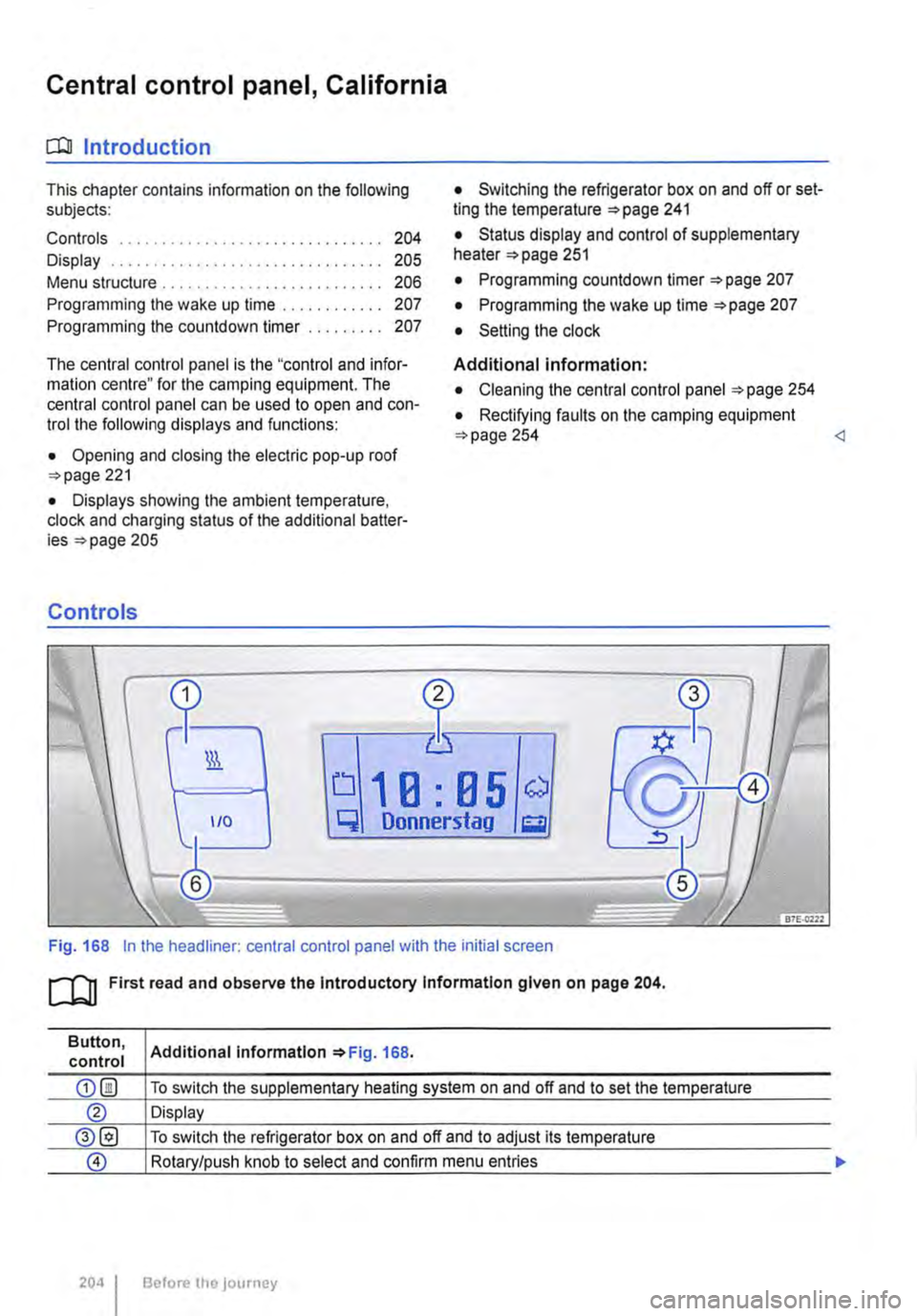
Controls
• Switching the refrigerator box on and off or set-ting the temperature =>page 241
• Status display and control of supplementary heater 251
• Programming countdown timer 207
• Programming the wake up time 207
• Setting the clock
Additional information:
• Cleaning the central control panel 254
• Rectifying faults on the camping equipment 254
q Donnerstag g
Fig. 168 In the headliner: central control panel with the initial screen
ro First read and observe the Introductory Information given on page 204.
Button, control
204 I
Additional Information 168.
To switch the supplementary heating system on and off and to set the temperature
Display
To switch the refrigerator box on and off and to adjust its temperature
Rotary/push knob to select and confirm menu entries
Before the journey
Page 243 of 486
• Pump for fresh water
• Auxiliary heater
230-volt grounded safety socket
The 230-volt grounded safety socket is supplied with 230 V alternating current via electrical feed from the external socket 242.
The following electrical consumers are supplied from the 230-volt power supply via the external socket:
• Battery charger
• Depending on the vehicle equipment, the 230-volt grounded safety socket is located in the side trim panel behind the left front seat or on the side of the kitchen unit 246.
230-volt Euro socket
The 230-volt Euro socket is supplied via additional batteries or via an inverter and is located in the side trim panel behind the left front seat 245.
Additional information:
• Electrical sockets page 163
• Battery 362
• Cigarette lighter 161
• Accessories, modifications, repairs and renewal of parts 394
• Fuses 429
• Consumer information 404
• Rectifying faults on the camping equipment 254
High voltage in the electrical system!
• Never pour any liquid over the socket.
• Do not plug any adapters or extension ca-bles into the 230-volt Euro socket. Otherwise the built-in child lock will disengage and pow-er will be supplied to the socket.
• Do not insert any items which will conduct electricity, such as knitting needles, into the contacts of the 230-volt Euro socket.
A WARNING
Improper use of the sockets and electrical ac-cessories can cause fires and severe Injuries.
• Never leave children in the vehicle unat-tended. Sockets and the devices connected to them can be used when the ignition is switched on.
A WARNING (Continued)
• If the electrical device gets too hot, switch off the device Immediately and disconnect it from the socket.
CD
• Observe the operating instructions for any device that you plug into the socket.
• Never exceed the maximum power rating as this could damage the whole vehicle electrical system.
• Only use accessories that have been ap-proved in accordance with valid guidelines concerning electromagnetic compatibility.
• Never feed electricity into the socket.
• Do not plug any heavy devices or connec-tions, such as mains adapters, directly Into the socket.
• Only connect devices to the socket with a voltage that matches the voltage of the socket.
CD
• In order to prevent damage to the electrical system, never connect equipment that gener-ates electricity, such as solar panels or battery chargers for charging the vehicle battery, to the 12-volt socket.
• Only use accessories that have been ap-proved in accordance with current guidelines concerning electromagnetic compatibility.
• In order to avoid damage due to voltage fluctuation, always switch any electrical con-sumers connected to the 12-volt sockets off be-fore switching the ignition or the engine on or off. When the start/stop system automatically switches off and restarts the engine, it is not necessary to switch off any connected electri-cal consumers.
• Never connect electrical devices requiring more electrical power to a 12-volt socket. The vehicle's electrical system can be damaged if the maximum power output is exceeded.
CD
• Observe the operating instructions for any device that you plug Into the socket.
• 230-volt Euro socket:
-Do not plug any heavy devices or connec-tions, such as mains adapters, directly into the socket. .,..
Equipment, California I 243
Page 245 of 486
230-volt power supply
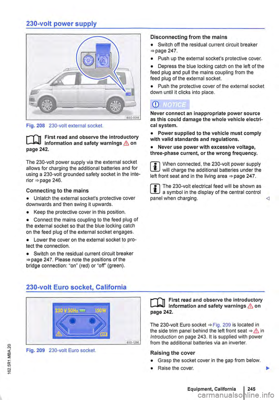
Fig. 208 230-volt external socket.
r-'('n First read and observe the introductory l.-Jo:-11 Information and safety warnings & on page 242.
The 230-volt power supply via the external socket allows for charging the additional batteries and for using a 230-volt grounded safety socket in the inte-rior 246.
Connecting to the mains
• Unlatch the external socket's protective cover downwards and then swing it upwards.
• Keep the protective cover in this position.
• Connect the mains coupling to the feed plug of the external socket so that the blue locking catch on the feed plug of the external socket engages.
• Lower the cover on the external socket to pro-tect the connection.
• Switch on the residual current circuit breaker 247. Please note the positions of the bridge connection: "on" (red) or "off' (green).
230-volt Euro socket, California
Disconnecting from the mains
• Switch off the residual current circuit breaker 247.
• Push up the external socket's protective cover.
• Depress the blue locking catch on the left of the feed plug and pull the mains coupling from the feed plug of the external socket.
• Push the protective cover of the external socket down until it clicks into place.
CD
Never connect an inappropriate power source as this could damage the whole vehicle electri-cal system.
• Power supplied to the vehicle must comply with valid standards and regulations.
• Never use power with excessive voltage, three-phase current, or the wrong frequency.
m When connected, the 230-volt power supply l!J will charge the additional batteries under the left front seat and in the living area 247.
m The 230-volt electrical feed will be shown as l!J a symbol in the display of the central control panel when charging.
The 230-volt Euro socket 209 is located in the side trim panel behind the left front seat & in Introduction on page 243. it is supplied with power L..---------------"'"30::c·.::."='" from the additional batteries via an inverter.
Fig. 209 230-volt Euro socket. Raising the cover
• Grasp the socket cover in the gap from below.
• Raise the cover. .,.
Equipment, California 245
Page 248 of 486
The batteries will become depleted if electrical consumers such as the auxiliary heater, refrigera-tor box or interior lights are used while the vehicle is stationary for long periods of time without re-charging the batteries. If the battery voltage falls below 11.5 volts, the auxiliary heater cannot be switched on.
The battery compartment and the battery charger are designed specifically for the factory-fitted AGM (absorbed glass mat) batteries &.
Additional batteries
r--f'n First read and observe the introductory information and safety warnings & on page 242.
The factory-fitted AGM batteries are located under the left front seat and in the wardrobe. They have deep discharge protection.
Should the additional batteries be subjected to deep discharge over a long period of time, they could be destroyed.
You can prevent deep discharge by:
• switching off the central control panel after charging,
• removing the fuses for the fresh water pump and the pop-up roof as necessary 249.
AGM batteries are maintenance free. do not leak their electrolyte, are robust and have extremely low gas emissions.
When should the additional battery be charged?
• If the additional battery is not charged by the al-ternator while the engine is running, the additional battery must be charged on the battery charger at regular intervals -every 4 weeks at the latest-for at least 12 hours.
• The additional battery must be recharged for at least 12 hours before the start of a journey if the battery has not been used for an extended period (e.g. seasonal use).
248 I Before the JOurney
A WARNING
If a conventional battery Is charged it will give off a highly explosive mixture of gases.
• Use only AGM batteries of the same type (batteries with the electrolyte absorbed Into a special fibreglass matting) and with the same specifications as the factory-fitted batteries.
• Never use conventional batteries (wet cells with liquid electrolyte).
If a conventional battery Is charged it will give off a highly explosive mixture of gases.
• Use only AGM batteries of the same type (batteries with the electrolyte absorbed into a special fibreglass matting) and with the same specifications as the factory-fitted batteries.
• Never use conventional batteries (wet cells with liquid electrolyte).
Page 254 of 486
Cleaning the cooker and sink
Clean the surfaces of the gas cooker and sink with commercially available non-abrasive cleaning Remove the pan supports from atop the burners to clean the surface of the gas cooker.
When cleaning the gas cooker, make sure that you do not damage or bend the heat sensors on the burners.
The gas burners should be cleaned with a brush at regular intervals.
CD
Abrasive sponges and cleaning agents can scratch and otherwise damage surfaces.
CD
Cleaning products that contain solvents, e.g. acetone, paint thinner, attack the material and can cause damage. <1
Cleaning the display of the central control panel
CD r-l'n First read and observe the Introductory L-l.::JJ information given on page 252. Do not use solvents such as turpentine or pet-
When cleaning the display, use an anti-static cloth or anti-static agent in order to prevent the build up of static charge on the display, which could render the display symbols unrecognizable
rol to clean the display, as these will damage lt.
[]J First read and observe the introductory information given on page 252.
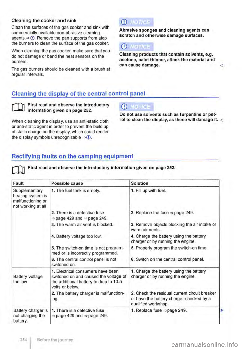
Fault Possible cause Solution
Supplementary 1. The fuel tank is empty. 1. Fill up with fuel. heating system is malfunctioning or not working at all
2. There is a defective fuse 2. Replace the fuse 249. 429 and 249.
3. The warm air vent is blocked. 3. Remove objects blocking the air intake or warm air vents.
4. Battery voltage too low. 4. Charge the battery using the battery charger or by running the engine.
5. The switch-on time is not program-5. Properly program the switch-on time. med or is incorrectly programmed.
6. The central control panel is not 6. Switch on the central control panel. switched on.
1. Electrical consumers have been 1. Charge the battery using the battery Battery voltage switched on and caused the voltage of charger or by running the engine. too low the additional battery to drop to 10.5 volts or below.
2. The battery charger is malfunction-2. Check the residual current circuit breaker ing. or have the battery charger checked by a qualified workshop.
Battery charger is 1. There is a defective fuse 1. Replace fuse =>page 249. not charging the 429 and 249. battery.
254 Before the journey
Page 283 of 486

A WARNING
Failure to observe illuminated warning lamps and text messages can lead to your vehicle breaking down in traffic, and can cause acci-dent and serious injury.
• Never ignore any illuminated warning lamps or text messages.
Start/stop system
Fig. 227 In the centre console: button for the start/stop system.
r--flt First read and observe the introductory l-J,::JJ information and safety warnings & on page 282.
When the start/stop mode is active, the
engine is switched off automatically
whenever the vehicle is stationary. When
required, the engine restarts automati-
cally.
The start/stop mode is activated automatically each time the ignition is switched on. The instru-ment cluster display will show information about the current status.
Always switch off the start/stop system manually when driving through water.
Start/stop mode on vehicles with a manual gearbox
• When the vehicle is stationary, disengage the gear and release the clutch pedal. The engine is stopped.
• Depress the clutch pedal to restart the engine.
A WARNING (Continued)
• Stop the vehicle as soon as possible and when safe to do so.
CD
Failure to observe illuminated indicator lamps and text messages can lead to your vehicle be-ing damaged.
• When the vehicle is stationary, press and hold the brake pedal. The engine is stopped.
• To restart the engine, remove your foot from the brake pedal or depress the accelerator in selector lever position P.
Important preconditions for automatic engine switch-off
• The driver is wearing their seat belt.
• All vehicle doors have been closed.
• The bonnet is closed.
• A minimum engine temperature has been reached and the internal engine conditions allow switch off.
• The vehicle has been moved since the engine was last switched off.
• The temperature set in the interior deviates too greatly from the ambient temperature.
• On vehicles with Climatronic: The temperature control is set to around +22oC (+ 72°F).
• The defrost function of the air conditioning sys-tem is not switched on.
• The charging state of the vehicle battery is suf-ficient.
• The temperature of the vehicle battery is not too low or too high.
• The vehicle is not on a steep incline.
• The steering is not turned greatly.
• Reverse gear is not engaged.
Conditions for an automatic restart
The engine can start automatically under the fol-lowing conditions: IIJ>
Driver assist systems 283
Page 340 of 486
At the filling station
Filling the tank
o:n Introduction
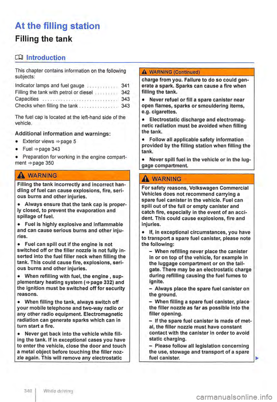
This chapter contains information on the following subjects:
Indicator lamps and fuel gauge . . . . . . . . . . . . 341
Filling the tank with petrol or diesel . . . . . . . . . 342
Capacities . . . . . . . . . . . 343
Checks when filling the tank . . . . . . . . . . . . . . . 343
The fuel cap is located at the left-hand side of the vehicle.
Additional information and warnings:
• Exterior views 5
• Fuel 343
• Preparation for working in the engine ccmpart-ment page 350
A WARNING
Filling the tank incorrectly and incorrect han-dling of fuel can cause explosions, fire, seri-ous burns and other injuries.
• Always ensure that the tank cap is proper-ly closed, to prevent the evaporation and spillage of fuel.
• Fuel is highly explosive and inflammable and can cause serious burns and other inju-ries.
• Fuel can spill out if the engine is not switched off or the filler nozzle is not fully in-serted into the fuel filler neck when filling the tank. This could cause fire, explosions, seri-ous burns and other Injuries.
• When refilling with fuel, the engine , sup-plementary heating system(=> page 332) and the ignition must be switched off for security reasons.
• When filling the tank, always switch off your mobile telephone and two-way radio or any other radio equipment. Electromagnetic radiation can generate sparks which can in turn start a fire.
• Never get back into the vehicle while fill-ing the tank. If in exceptional cases you have to enter the vehicle, close the door and touch a metal object before touching the filler noz-zle again. This will remove any electrostatic
340 I While driving
A WARNING (Continued)
charge from you. Failure to do so could gen-erate a spark. Sparks can cause a fire when filling the tank.
• Never refuel or fill a spare canister near open flames, sparks or smouldering Items, e.g. cigarettes.
• Electrostatic discharge and electromag-netic radiation must be avoided when filling the tank.
• Follow all applicable safety information provided by the filling station when filling the tank.
• Never spill fuel in the vehicle or In the lug-gage compartment
A WARNING
For safety reasons, Volkswagen Commercial Vehicles does not recommend carrying a spare fuel canister In the vehicle. Fuel can spill out of the full or empty canister and catch fire, especially In the event of an acci-dent. This could cause explosions, fire and injuries.
• If, In exceptional circumstances, you have to transport a spare fuel canister, please note the following:
-When refilling never place the canister In or on top of the vehicle, for example In the luggage compartment or on the tall-gate. There may be an electrostatic charge during refilling causing the fuel fumes to Ignite.
-Always place the spare fuel canister on the ground.
-When filling a spare fuel canister, place the filler nozzle as far as possible Into the filler opening.
-If the spare fuel canister Is made of met-al, the filler nozzle must have constant contact with the canister In order to avoid static charging.
-Please follow all legislation concerning the use, stowage and transport of a spare fuel canister.
Page 362 of 486
A WARNING (Continued)
-Always keep children away from the en-gine compartment and never leave the ve-hicle unattended.
• The engine cooling system is under pres-sure when the engine is hot. Never open the cap of the coolant expansion tank when the engine is hot. Coolant may spray out and cause serious burns and other injuries.
-Turn the cap slowly and very carefully anti-clockwise while exerting gentle down-ward pressure on the cap.
-Always protect the face, hands and arms from hot coolant or steam with a large, thick cloth.
• When refilling, do not spill any service flu-ids on engine components or on the exhaust system. The spilt service fluids can start a fire. In certain circumstances, the ethylene glycol in the engine can catch fire.
CD
• Refill only with distilled water. All other types of water can cause corrosion in the en-gine due to the chemical components con-
Vehicle battery
CQJ Introduction
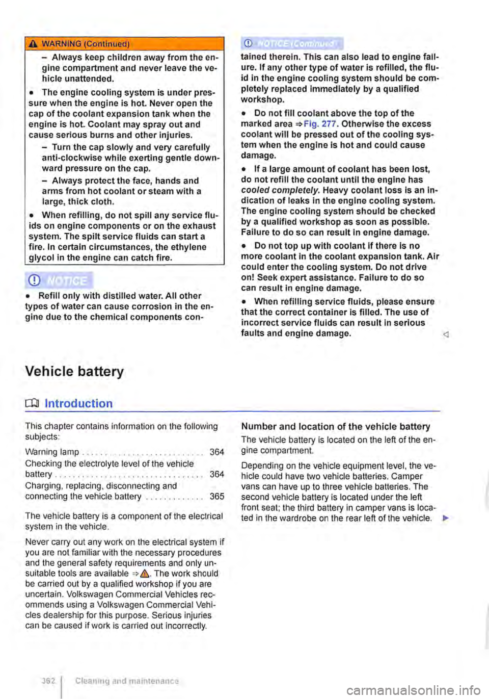
This chapter conlains information on the following subjects:
Warning lamp . . . . . . . . . . . . . . . . . . . . . . . . . . . 364
Checking the electrolyte level of the vehicle battery ................................. 364 Charging, replacing, disconnecling and connecting the vehicle battery . . . . . . . . . . . . . 365
The vehicle battery is a component of the electrical system in the vehicle.
Never carry out any work on the electrical system if you are not familiar with the necessary procedures and the general safety requirements and only un-suitable tools are available => &. The work should be carried out by a qualified workshop if you are uncertain. Volkswagen Commercial Vehicles rec-ommends using a Volkswagen Commercial Vehi-cles dealership for this purpose. Serious injuries can be caused if work is carried out incorrectly.
3621 Cleaning and maintenance
(j)
tained therein. This can also lead to engine fail-ure. If any other type of water is refilled, the flu-id in the engine cooling system should be com-pletely replaced immediately by a qualified workshop.
• Do not fill coolant above the top of the marked area =>Fig. 277. Otherwise the excess coolant will be pressed out of the cooling sys-tem when the engine is hot and could cause damage.
• If a large amount of coolant has been lost, do not refill the coolant until the engine has cooled completely. Heavy coolant loss is an in-dication of leaks in the engine cooling system. The engine cooling system should be checked by a qualified workshop as soon as possible. Failure to do so can result in engine damage.
• Do not top up with coolant if there is no more coolant in the coolant expansion tank. Air could enter the cooling system. Do not drive on! Seek expert assistance. Failure to do so can result in engine damage.
• When refilling service fluids, please ensure that the correct container is filled. The use of incorrect service fluids can result In serious faults and engine damage.
The vehicle battery is located on the left of the en-gine compartment.
Depending on the vehicle equipment level, the ve-hicle could have two vehicle batteries. Camper vans can have up to three vehicle batteries. The second vehicle battery is located under the left front seat: the third battery in camper vans is loca-ted in the wardrobe on the rear left of the vehicle. •