Page 195 of 406

183
3-2. Using the audio system
3
Interior features
n
If the satellite radio does not operate normally
If a problem occurs with the XM
® tuner, a message will appear on the dis-
play. Refer to the table below to identify the problem, and take the suggested
corrective action.
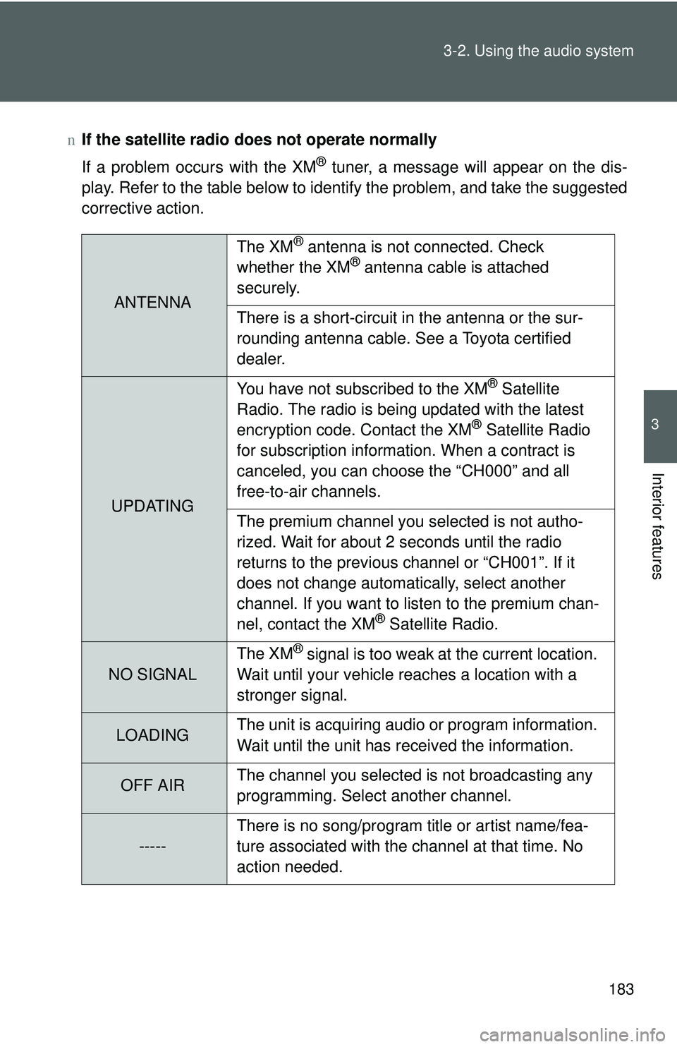
ANTENNA The XM
® antenna is not connected. Check
whether the XM® antenna cable is attached
securely.
There is a short-circuit in the antenna or the sur-
rounding antenna cable. See a Toyota certified
dealer.
UPDATING You have not subscribed to the XM
® Satellite
Radio. The radio is being updated with the latest
encryption code. Contact the XM
® Satellite Radio
for subscription information. When a contract is
canceled, you can choose the “CH000” and all
free-to-air channels.
The premium channel you selected is not autho-
rized. Wait for about 2 seconds until the radio
returns to the previous channel or “CH001”. If it
does not change automatically, select another
channel. If you want to listen to the premium chan-
nel, contact the XM
® Satellite Radio.
NO SIGNAL The XM
® signal is too weak at the current location.
Wait until your vehicle reaches a location with a
stronger signal.
LOADING The unit is acquiring audio or program information.
Wait until the unit has received the information.
OFF AIRThe channel you selected is not broadcasting any
programming. Select another channel.
-----There is no song/program title or artist name/fea-
ture associated with the channel at that time. No
action needed.
Page 229 of 406

217
3-5. Other interior features
3
Interior features
Floor mat
CAUTION
Observe the following precautions.
Failure to do so may cause the driver’s floor mat to slip, possibly interfering
with the pedals while driving. An unexpectedly high speed may result or it may
become difficult to stop the vehicle, leading to a serious accident.
nWhen installing the driver’s floor mat
lDo not use floor mats designed for other models or different model year
vehicles, even if they are Toyota Genuine floor mats.
l Only use floor mats designed for the driver’s seat.
l Always install the floor mat securely using the retaining hooks (clips) pro-
vided.
l Do not use two or more floor mats on top of each other.
l Do not place the floor mat bottom-side up or upside-down.
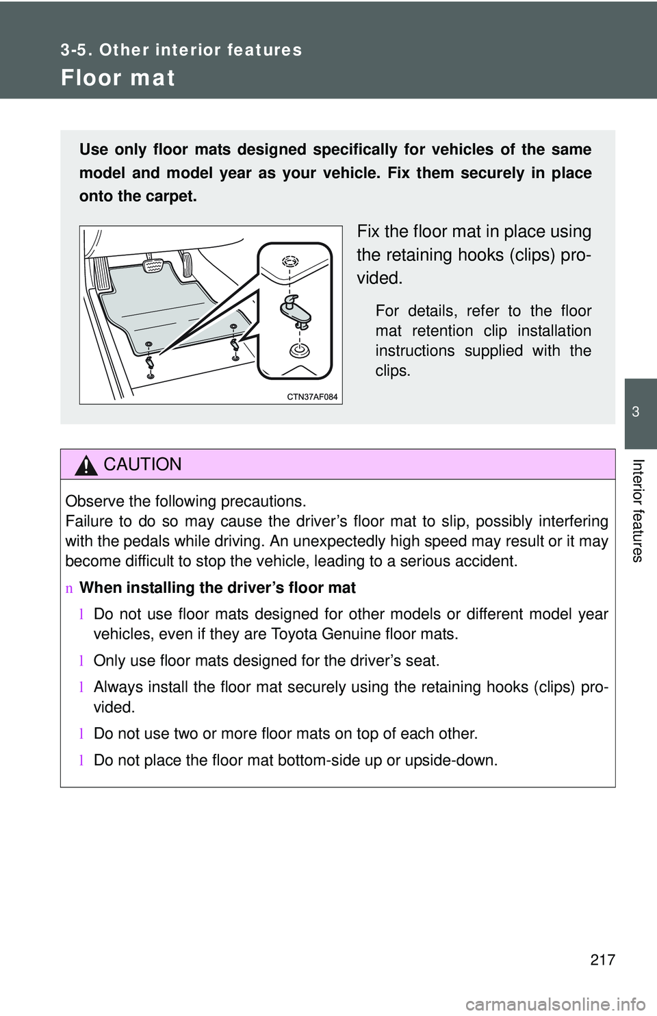
Use only floor mats designed specifically for vehicles of the same
model and model year as your vehic le. Fix them securely in place
onto the carpet.
Fix the floor mat in place using
the retaining hooks (clips) pro-
vided.
For details, refer to the floor
mat retention clip installation
instructions supplied with the
clips.
Page 230 of 406
218 3-5. Other interior features
CAUTION
nBefore driving
lCheck that the floor mat is securely
fixed in the right place with all the pro-
vided retaining hooks (clips). Be espe-
cially careful to perform this check after
cleaning the floor.
l With the engine stopped and the shift
lever in P (automatic transmission) or N
(manual transmission), fully depress
each pedal to the floor to make sure it
does not interfere with the floor mat.
Page 239 of 406
228 4-2. Maintenance
Vehicle interior
ItemsCheck points
Accelerator pedal • Moves smoothly (without uneven
pedal effort or catching)?
Automatic transmission “Park”
mechanism • Can the vehicle be hold securely
on an incline with the shift lever in
P?
Brake pedal • Moves smoothly?
• Does it have appropriate clear-
ance and correct amount of free
play?
Brakes • Not pull to one side when
applied?
• Loss of brake effectiveness?
• Spongy feeling brake pedal?
• Pedal almost touches floor?
Clutch pedal • Moves smoothly?
• Does it have correct amount of
free play?
Head restraints • Move smoothly and lock
securely?
Indicators/buzzers • Function properly?
Lights • Do all the lights come on?
• Headlights aimed correctly?
Parking brake • Moves smoothly?
• Can hold the vehicle securely on
an incline?
Seat belts • Does the seat belt system oper-
ate smoothly?
• Are the belts undamaged?
Seats • Do the seat controls operate
properly?
Page 282 of 406
271
4-3. Do-it-yourself maintenance
4
Maintenance and care
Fuse layout and amperage ratings
■ Engine compartment (type A)
FuseAmpereCircuit
1 ALT 120 A Charging system, HTR SUB2,
EPS, ABS1/VSC1, HTR, ABS2/
VSC2, HTR SUB1, RDI, DEF, FR
FOG, OBD2, D/L, POWER, RR
DOOR, RL DOOR, STOP and AM1
2 MAIN 60 A EFI, HORN, AM2, ALT-S, DOME,
ST, ECU-B, ETCS, HAZ, H-LP LH/
H-LP LO LH and H-LP RH/H-LP
LO RH fuses
Page 284 of 406

273
4-3. Do-it-yourself maintenance
4
Maintenance and care
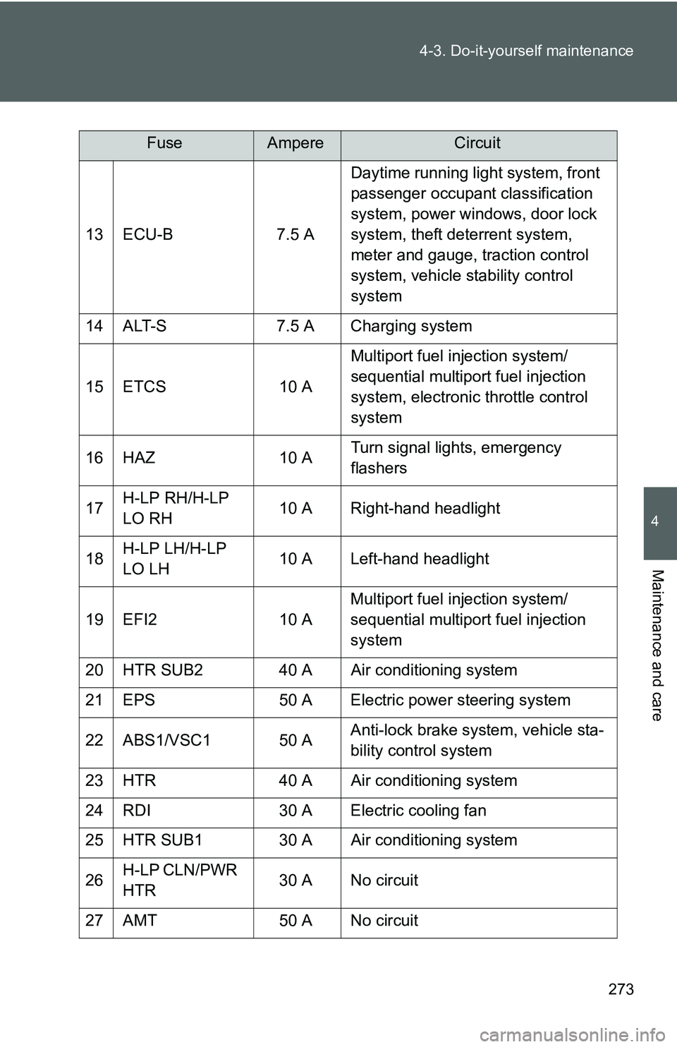
13 ECU-B
7.5 ADaytime running light system, front
passenger occupant classification
system, power windows, door lock
system, theft deterrent system,
meter and gauge, traction control
system, vehicle stability control
system
14 ALT-S 7.5 A Charging system
15 ETCS 10 AMultiport fuel injection system/
sequential multiport fuel injection
system, electronic throttle control
system
16 HAZ 10 ATurn signal lights, emergency
flashers
17 H-LP RH/H-LP
LO RH 10 A Right-hand headlight
18 H-LP LH/H-LP
LO LH 10 A Left-hand headlight
19 EFI2 10 AMultiport fuel injection system/
sequential multiport fuel injection
system
20 HTR SUB2 40 A Air conditioning system
21 EPS 50 A Electric power steering system
22 ABS1/VSC1 50 A Anti-lock brake system, vehicle sta-
bility control system
23 HTR 40 A Air conditioning system
24 RDI 30 A Electric cooling fan
25 HTR SUB1 30 A Air conditioning system
26 H-LP CLN/PWR
HTR 30 A No circuit
27 AMT 50 A No circuit
FuseAmpereCircuit
Page 287 of 406

276 4-3. Do-it-yourself maintenance
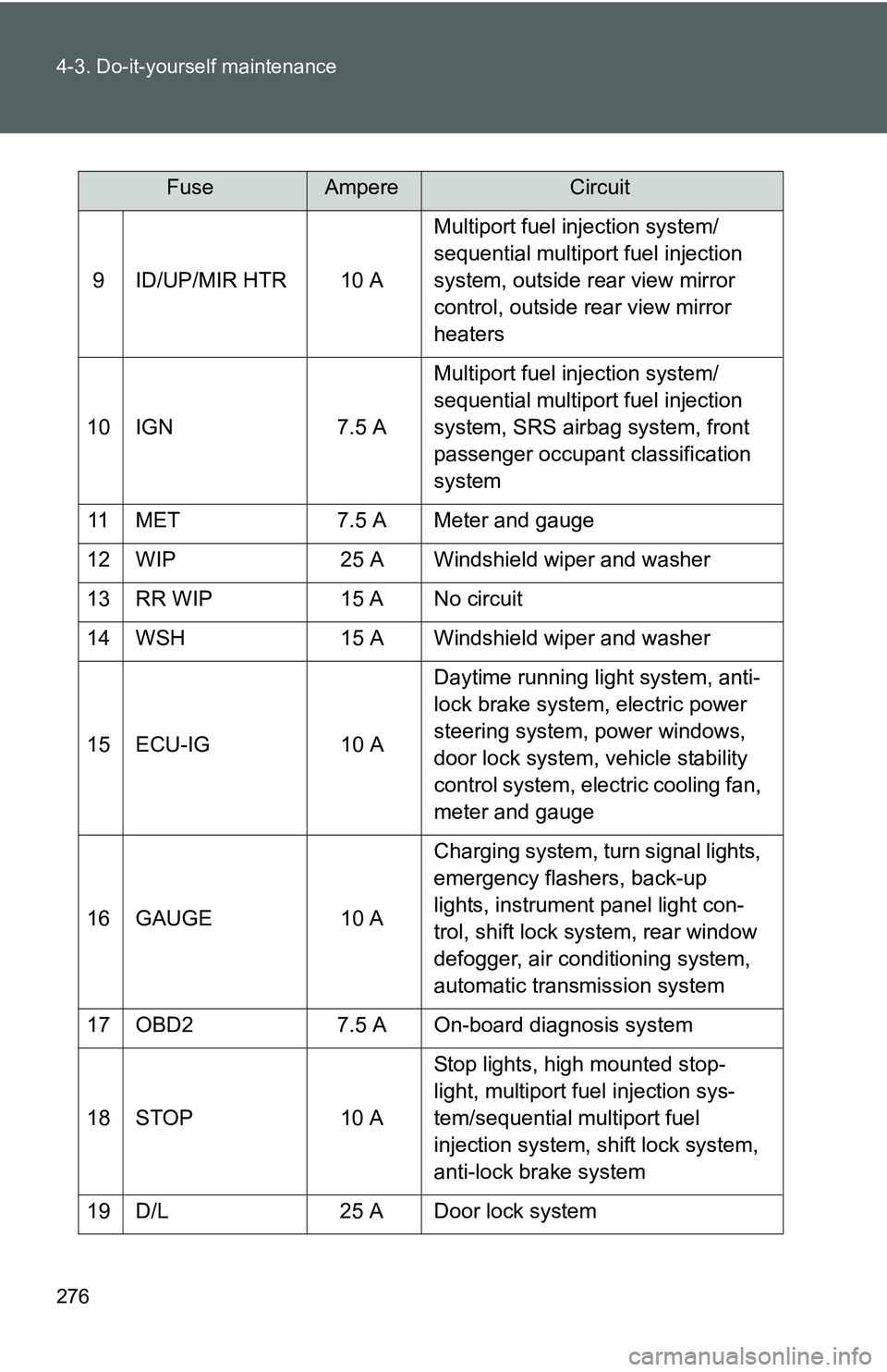
9 ID/UP/MIR HTR 10 AMultiport fuel injection system/
sequential multiport fuel injection
system, outside rear view mirror
control, outside rear view mirror
heaters
10 IGN 7.5 A Multiport fuel injection system/
sequential multiport fuel injection
system, SRS airbag system, front
passenger occupant classification
system
11 MET 7.5 A Meter and gauge
12 WIP 25 A Windshield wiper and washer
13 RR WIP 15 A No circuit
14 WSH 15 A Windshield wiper and washer
15 ECU-IG 10 A Daytime running light system, anti-
lock brake system, electric power
steering system, power windows,
door lock system, vehicle stability
control system, electric cooling fan,
meter and gauge
16 GAUGE 10 A Charging system, turn signal lights,
emergency flashers, back-up
lights, instrument panel light con-
trol, shift lock system, rear window
defogger, air conditioning system,
automatic transmission system
17 OBD2 7.5 A On-board diagnosis system
18 STOP 10 A Stop lights, high mounted stop-
light, multiport fuel injection sys-
tem/sequential multiport fuel
injection system, shift lock system,
anti-lock brake system
19 D/L 25 A Door lock system
FuseAmpereCircuit
Page 298 of 406
287
4-3. Do-it-yourself maintenance
4
Maintenance and care
■
Installing the clips
CAUTION
■Replacing light bulbs
Turn off the headlights. Do not attempt to replace the bulb immediately after
turning off the headlights.
The bulbs become very hot and may cause burns.
■ To prevent damage or fire
Make sure bulbs are fully seated and locked.
NOTICE
●Halogen bulbs have pressurized gas inside and require special handling. \
Do
not touch the glass portion of the light bulb with bare hands. Hold the bulb by
the plastic or metal portion.
If the bulb is scratched or dropped it may blow out or crack.
● Fully install light bulbs and any parts used to secure them. Failing to do so
may result in heat damage, fire, or water entering the headlight unit. This
may damage the headlights or cause condensation to build up on the lens.
Insert the clips.