2011 SUBARU TRIBECA battery
[x] Cancel search: batteryPage 219 of 422
6-2Interior equipment
Interior light
When leaving your vehicle, make sure the
lights are turned off to avoid batterydischarge. &Dome light
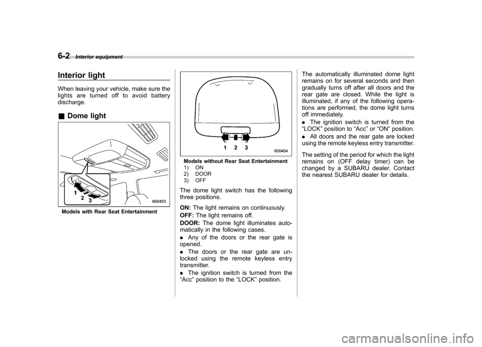
Models with Rear Seat Entertainment
Models without Rear Seat Entertainment
1) ON
2) DOOR
3) OFF
The dome light switch has the following
three positions. ON: The light remains on continuously.
OFF: The light remains off.
DOOR: The dome light illuminates auto-
matically in the following cases. . Any of the doors or the rear gate is
opened.. The doors or the rear gate are un-
locked using the remote keyless entry
transmitter. . The ignition switch is turned from the
“ Acc ”position to the “LOCK ”position. The automatically illuminated dome light
remains on for several seconds and then
gradually turns off after all doors and the
rear gate are closed. While the light is
illuminated, if any of the following opera-
tions are performed, the dome light turns
off immediately. .
The ignition switch is turned from the
“ LOCK ”position to “Acc ”or “ON ”position.
. All doors and the rear gate are locked
using the remote keyless entry transmitter.
The setting of the period for which the light
remains on (OFF delay timer) can be
changed by a SUBARU dealer. Contact
the nearest SUBARU dealer for details.
Page 220 of 422
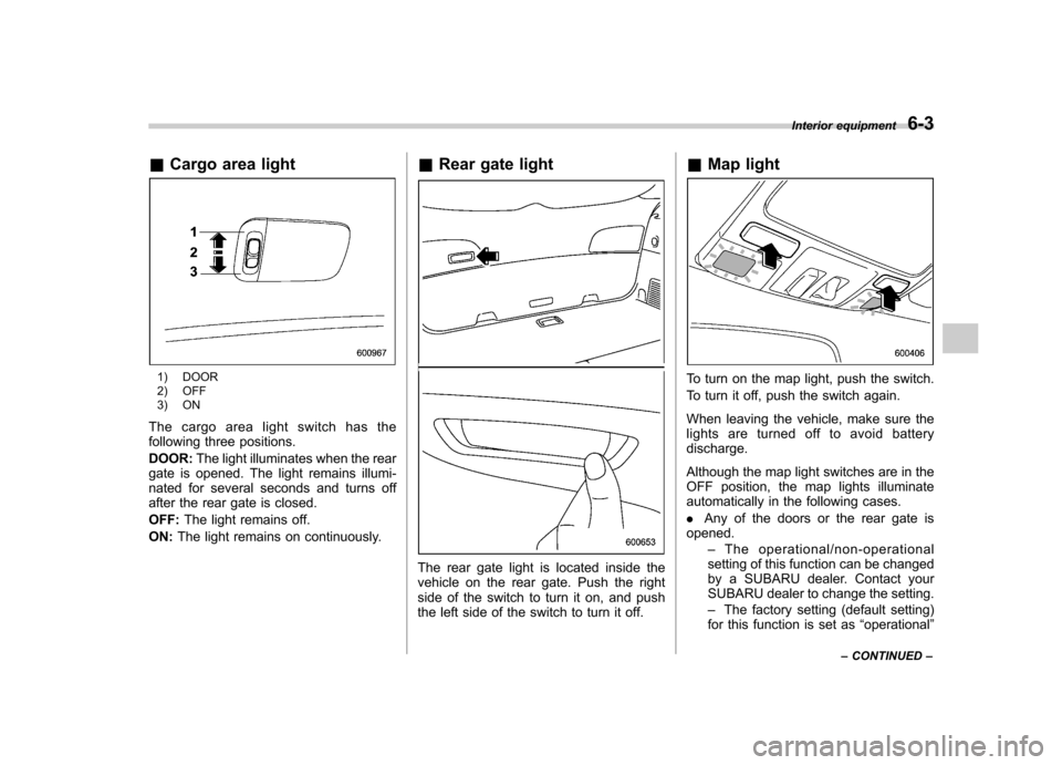
&Cargo area light
1) DOOR
2) OFF
3) ON
The cargo area light switch has the
following three positions. DOOR: The light illuminates when the rear
gate is opened. The light remains illumi-
nated for several seconds and turns off
after the rear gate is closed. OFF: The light remains off.
ON: The light remains on continuously. &
Rear gate light
The rear gate light is located inside the
vehicle on the rear gate. Push the right
side of the switch to turn it on, and push
the left side of the switch to turn it off. &
Map light
To turn on the map light, push the switch.
To turn it off, push the switch again.
When leaving the vehicle, make sure the
lights are turned off to avoid batterydischarge.
Although the map light switches are in the
OFF position, the map lights illuminate
automatically in the following cases. .Any of the doors or the rear gate is
opened.
–The operational/non-operational
setting of this function can be changed
by a SUBARU dealer. Contact your
SUBARU dealer to change the setting. – The factory setting (default setting)
for this function is set as “operational ”
Interior equipment
6-3
– CONTINUED –
Page 221 of 422
6-4Interior equipment
(automatic illumination - ON).
. The doors are unlocked using the
remote keyless entry transmitter. . The ignition switch is turned from the
“ Acc ”position to the “LOCK ”position.
The automatically illuminated map lights
remain illuminated for several seconds
and then gradually turn off after all doors
are closed.
While the lights are illuminated, if any of
the following operations are performed,
the map lights turn off immediately. . The ignition switch is turned from the
“ LOCK ”position to the “Acc ”or “ON ”
position.. All doors and the rear gate are locked
using the remote keyless entry transmitter.
The setting of the period for which the light
remains illuminated (OFF delay timer) can
be changed by a SUBARU dealer. Con-
tact your SUBARU dealer for details.
NOTE
If any of the doors or the rear gate is
not completely closed, the map lights
will remain illuminated as a result.
However, the map lights are automati-
cally turned off by the battery drainage
prevention functi on to prevent the
battery from discharging. For details, refer to
“Battery drainage prevention
function ”F 2-6.
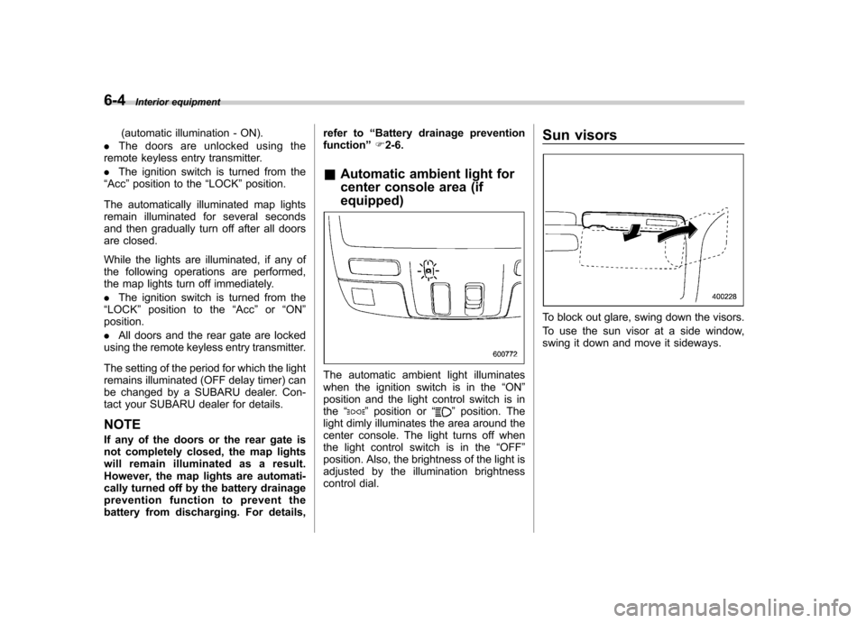
& Automatic ambient light for
center console area (if equipped)
The automatic ambient light illuminates
when the ignition switch is in the “ON ”
position and the light control switch is inthe “
”position or “”position. The
light dimly illuminates the area around the
center console. The light turns off when
the light control switch is in the “OFF ”
position. Also, the brightness of the light is
adjusted by the illumination brightness
control dial. Sun visors
To block out glare, swing down the visors.
To use the sun visor at a side window,
swing it down and move it sideways.
Page 222 of 422
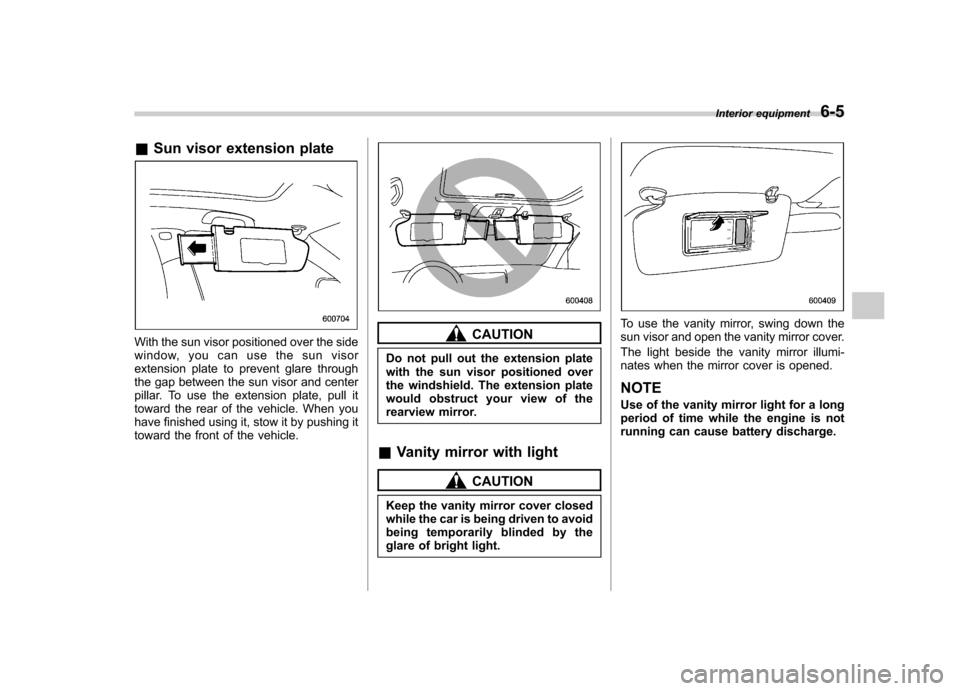
&Sun visor extension plate
With the sun visor positioned over the side
window, you can use the sun visor
extension plate to prevent glare through
the gap between the sun visor and center
pillar. To use the extension plate, pull it
toward the rear of the vehicle. When you
have finished using it, stow it by pushing it
toward the front of the vehicle.CAUTION
Do not pull out the extension plate
with the sun visor positioned over
the windshield. The extension plate
would obstruct your view of the
rearview mirror.
& Vanity mirror with light
CAUTION
Keep the vanity mirror cover closed
while the car is being driven to avoid
being temporarily blinded by the
glare of bright light.
To use the vanity mirror, swing down the
sun visor and open the vanity mirror cover.
The light beside the vanity mirror illumi-
nates when the mirror cover is opened. NOTE
Use of the vanity mirror light for a long
period of time while the engine is not
running can cause battery discharge. Interior equipment
6-5
Page 227 of 422
6-10Interior equipment
trim can be used to hold beverage bottles
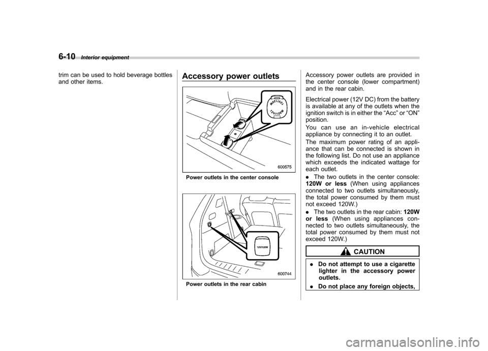
and other items. Accessory power outlets
Power outlets in the center console
Power outlets in the rear cabinAccessory power outlets are provided in
the center console (lower compartment)
and in the rear cabin.
Electrical power (12V DC) from the battery
is available at any of the outlets when the
ignition switch is in either the
“Acc ”or “ON ”
position.
You can use an in-vehicle electrical
appliance by connecting it to an outlet.
The maximum power rating of an appli-
ance that can be connected is shown in
the following list. Do not use an appliance
which exceeds the indicated wattage for
each outlet. . The two outlets in the center console:
120W or less (When using appliances
connected to two outlets simultaneously,
the total power consumed by them must
not exceed 120W.) . The two outlets in the rear cabin: 120W
or less (When using appliances con-
nected to two outlets simultaneously, the
total power consumed by them must not
exceed 120W.)
CAUTION
. Do not attempt to use a cigarette
lighter in the accessory power outlets.
. Do not place any foreign objects,
Page 228 of 422
especially metal ones such as
coins or aluminum foil, into the
accessory power outlet. That
could cause a short circuit. Al-
ways put the cap on the acces-
sory power outlet when it is not
in use.
. Use only electrical appliances
which are designed for 12V DC.
The maximum power rating of an
appliance that can be connected
is shown in the following list. Do
not use an appliance which ex-
ceeds the indicated wattage for
each outlet. – The two outlets in the center
console: 120W or less (When
using appliances connected
to two outlets simultaneously,
the total power consumed by
them must not exceed 120W.)
– The two outlets in the rear
cabin: 120W or less (When
using appliances connected
to two outlets simultaneously,
the total power consumed by
them must not exceed 120W.)
Overloading the accessory
power outlet can cause a short
circuit. Do not use dual adapters
or more than one electrical appli- ance.
. If the plug on your electric appli-
ance is either too loose or too
tight for the accessory power
outlet, this can result in a poor
contact or cause the plug to get
stuck. Only use plugs that fit
properly.
. Use of an electric appliance in the
accessory power outlet for a long
period of time while the engine is
not running can cause batterydischarge.
. Before driving your vehicle, make
sure that the plug and the cord
on your electrical appliance will
not interfere with your shifting
gears and operating the accel-
erator and brake pedals. If they
do, do not use the electrical
appliance while driving.
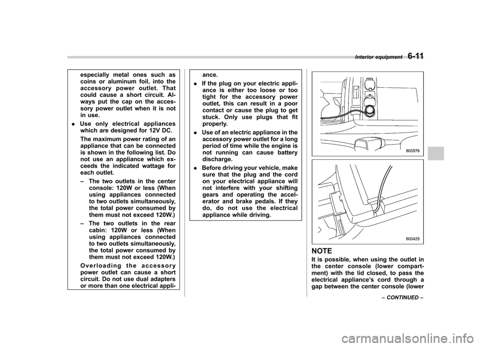
NOTE
It is possible, when using the outlet in
the center console (lower compart-
ment) with the lid closed, to pass the
electrical appliance ’s cord through a
gap between the center console (lower Interior equipment
6-11
– CONTINUED –
Page 235 of 422
6-18Interior equipment
NOTE . After programming your HomeLink
®
Wireless Control System for the de-
sired devices, retain the hand-held
transmitters for further programming
or device testing in the event of aproblem..It is recommended that you insert a
new battery in the hand-held transmit-
ter of a device to ensure correctprogramming. & Garage door opener pro-
gramming in the U.S.A.
NOTE
When programming the HomeLink
®
Wireless Control System for a garage
door opener, it is suggested that you
park the vehicle outside the garage.
1. Unplug the motor of the garage door
opener from the outlet. NOTE
If any of the HomeLink
®buttons are
already programmed for other devices,
skip step 2 because it clears the
memory of all the three buttons.
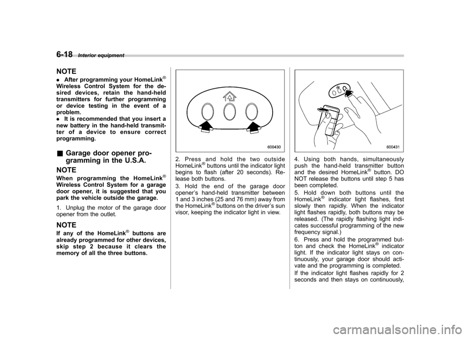
2. Press and hold the two outside HomeLink®buttons until the indicator light
begins to flash (after 20 seconds). Re-
lease both buttons.
3. Hold the end of the garage door opener ’s hand-held transmitter between
1 and 3 inches (25 and 76 mm) away from
the HomeLink
®buttons on the driver ’s sun
visor, keeping the indicator light in view.
4. Using both hands, simultaneously
push the hand-held transmitter button
and the desired HomeLink
®button. DO
NOT release the buttons until step 5 has
been completed.
5. Hold down both buttons until the
HomeLink
®indicator light flashes, first
slowly then rapidly. When the indicator
light flashes rapidly, both buttons may be
released. (The rapidly flashing light indi-
cates successful programming of the new
frequency signal.)
6. Press and hold the programmed but-
ton and check the HomeLink
®indicator
light. If the indicator light stays on con-
tinuously, your garage door should acti-
vate and the programming is completed.
If the indicator light flashes rapidly for 2
seconds and then stays on continuously,
Page 239 of 422
6-22Interior equipment
the surrounding area with your
eyes and mirrors, and move
backward at a slow speed. Mov-
ing backward only by checking
the rear view image from the
camera could cause an accident.
. Do not disassemble or modify the
camera, switch or wiring. If
smoke comes out or you smell
a strange odor, stop using the
rear view camera immediately.
Contact your SUBARU dealer
for an inspection. Continued use
may result in accident, fire or
electric shock.
CAUTION
. If your vehicle is washed with a
high-pressure washer, do not
allow water to contact the camera
directly. Entry of water in the
camera lens may result in con-
densation, malfunction, fire or
electric shock.
. Since the camera is a precision
device, do not subject it to strong
impacts. Otherwise, malfunction,
fire or electric shock may occur.
. If mud or snow sticks to or is
frozen on the camera, you must be very careful removing it.
Otherwise, damage done to the
camera may cause a fire or
electric shock. Pour water or
lukewarm water over the camera
to remove mud and ice, and wipe
it with a soft, dry cloth.
. Do not put a flame close to the
camera or wiring. Otherwise, da-
mage or fire may occur.
. When replacing the fuse, be sure
to use a fuse with the specified
rating. Use of a fuse with a
different rating may result in amalfunction.
. If the rear view camera is used for
a long time while the engine is
not operated, the battery may
become completely discharged.
NOTE . Do not wipe the camera with alcohol,
benzine or paint thinner. Otherwise,
discoloration may occur. To remove
contamination, wipe the camera with a
cloth moistened with a diluted neutral
detergent and then wipe it with a soft,
dry cloth.. When waxing the vehicle, be careful
not to apply the wax to the camera. If it
comes in contact with the camera, moisten a clean cloth with a diluted
neutral detergent to remove the wax..
The camera lens has hard coating to
help prevent scratches. However, when
washing the vehicle or cleaning the
camera lens, be careful not to scratch
the camera lens. Do not use a washing
brush directly on the camera lens. The
monitor screen may be adversely af-fected.. Strong light shined on the camera
lens may develop white light stripes
around the light source. This is not amalfunction.. Under the fluorescent light, the dis-
play may flicker. However, this is not a malfunction. . The image of the rear view camera
may be slightly different from the
actual color of the objects. & How to use the rear view camera
When the select lever is set to “R ”, the rear
view camera automatically displays the
rear view image from the vehicle. When
the lever is set to other positions, the
image before setting to “R ”is displayed.
1. Set the ignition switch to “ON ”.
2. Set the select lever to “R ”.