2011 SUBARU TRIBECA fog light
[x] Cancel search: fog lightPage 181 of 422
4-8Climate control
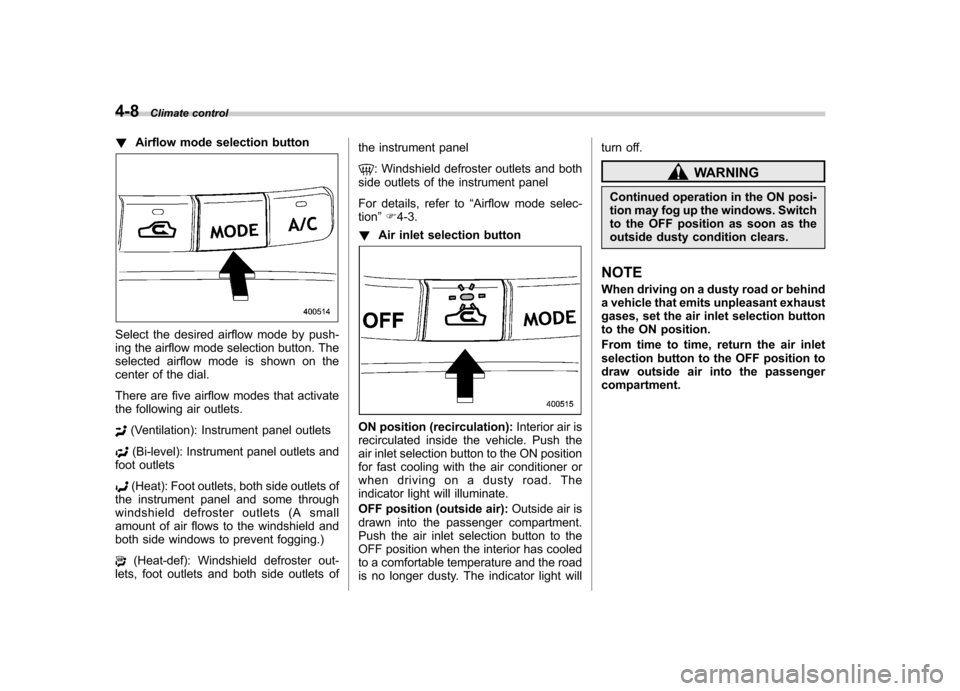
!Airflow mode selection button
Select the desired airflow mode by push-
ing the airflow mode selection button. The
selected airflow mode is shown on the
center of the dial.
There are five airflow modes that activate
the following air outlets.
(Ventilation): Instrument panel outlets
(Bi-level): Instrument panel outlets and
foot outlets
(Heat): Foot outlets, both side outlets of
the instrument panel and some through
windshield defroster outlets (A small
amount of air flows to the windshield and
both side windows to prevent fogging.)
(Heat-def): Windshield defroster out-
lets, foot outlets and both side outlets of the instrument panel
: Windshield defroster outlets and both
side outlets of the instrument panel
For details, refer to “Airflow mode selec-
tion ”F 4-3.
! Air inlet selection button
ON position (recirculation): Interior air is
recirculated inside the vehicle. Push the
air inlet selection button to the ON position
for fast cooling with the air conditioner or
when driving on a dusty road. The
indicator light will illuminate.
OFF position (outside air): Outside air is
drawn into the passenger compartment.
Push the air inlet selection button to the
OFF position when the interior has cooled
to a comfortable temperature and the road
is no longer dusty. The indicator light will turn off.
WARNING
Continued operation in the ON posi-
tion may fog up the windows. Switch
to the OFF position as soon as the
outside dusty condition clears.
NOTE
When driving on a dusty road or behind
a vehicle that emits unpleasant exhaust
gases, set the air inlet selection button
to the ON position.
From time to time, return the air inlet
selection button to the OFF position to
draw outside air into the passengercompartment.
Page 333 of 422
Maintenance and serviceRear window wiper blade rubber ....................... 11-32
Battery. .............................................................. 11-34
Fuses ................................................................ 11-35
Main fuse .......................................................... 11-36
Installation of accessories ............................... 11-37
Replacing bulbs ............................................... 11-37
Headlights (models with HID headlights) ........... 11-37
Headlights (models without HID headlights) .. .... 11-37
Parking light (right-hand side) ........................... 11-39
Front turn signal light (right-hand side) ............. 11-40Front fog light
.................................................. 11-40
Rear combination lights ................................... 11-40
Back-up light/Tail light ..................................... 11-41
Rear gate light ................................................. 11-42
License plate light ........................................... 11-42
Dome light ....................................................... 11-43
Map light ......................................................... 11-44
Vanity mirror light ............................................ 11-44
Door step light ................................................. 11-44
Cargo area light ............................................... 11-45
Page 368 of 422
Installation of accessories
Always consult your SUBARU dealer
before installing fog lights or any other
electrical equipment in your vehicle. Such
accessories may cause the electronic
system to malfunction if they are incor-
rectly installed or if they are not suited for
the vehicle.Replacing bulbs
WARNING
Bulbs may become very hot while
illuminated. Before replacing bulbs,
turn off the bulbs and wait until the
bulbs cool down. Otherwise, there is
a risk of sustaining a burn injury.
CAUTION
Replace any bulb only with a new
bulb of the specified wattage. Using
a bulb of different wattage could
result in a fire. For the specified
wattage of each bulb, refer to “Bulb
chart ”F 12-13.
& Headlights (models with HID headlights)
WARNING
High-intensity-discharge (HID) bulbs
are used for the low beams of the
headlights. These HID bulbs use an
extremely high voltage. To avoid the
risk of an electric shock that could
result in serious injury, observe the following precautions. .
Do not replace any headlight
bulbs (both low beam and high
beam) by yourself.
. Do not remove/restore the head-
light assemblies by yourself.
. Do not remove any headlight-
assembly components by your-self.
For replacement, contact your
SUBARU dealer.
& Headlights (models without
HID headlights)
CAUTION
Halogen headlight bulbs become
very hot while in use. If you touch
the bulb surface with bare hands or
greasy gloves, fingerprints or
grease on the bulb surface will
develop into hot spots, causing the
bulb to break. If there are finger
prints or grease on the bulb surface,
wipe them away with a soft cloth
moistened with alcohol. Maintenance and service
11-37
– CONTINUED –
Page 371 of 422
11-40Maintenance and service
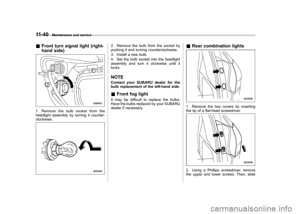
& Front turn signal light (right-
hand side)
1. Remove the bulb socket from the
headlight assembly by turning it counter-clockwise.
2. Remove the bulb from the socket by
pushing it and turning counterclockwise.
3. Install a new bulb.
4. Set the bulb socket into the headlight
assembly and turn it clockwise until itlocks. NOTE
Contact your SUBARU dealer for the
bulb replacement of the left-hand side. &Front fog light
It may be difficult to replace the bulbs.
Have the bulbs replaced by your SUBARU
dealer if necessary. &
Rear combination lights
1. Remove the two covers by inserting
the tip of a flat-head screwdriver.
2. Using a Phillips screwdriver, remove
the upper and lower screws. Then, slide
Page 388 of 422
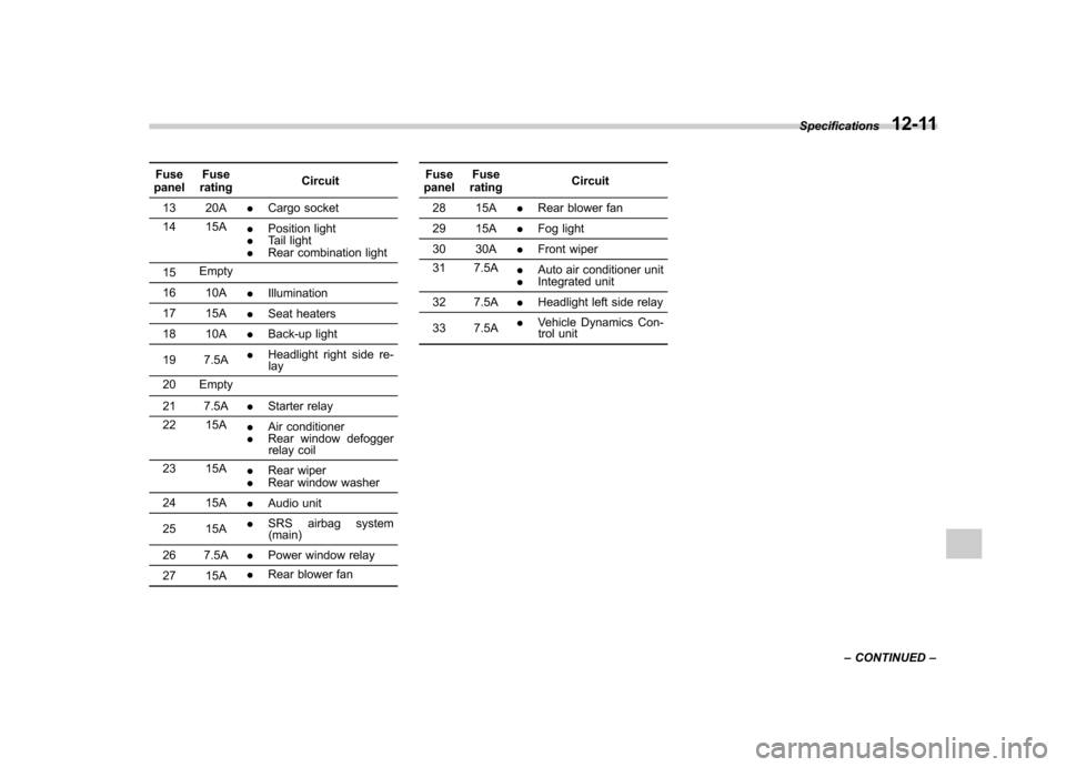
Fuse
panel Fuse
rating Circuit
13 20A .Cargo socket
14 15A .Position light
. Tail light
. Rear combination light
15 Empty
16 10A .Illumination
17 15A .Seat heaters
18 10A .Back-up light
19 7.5A .
Headlight right side re-
lay
20 Empty
21 7.5A .Starter relay
22 15A .Air conditioner
. Rear window defogger
relay coil
23 15A .Rear wiper
. Rear window washer
24 15A .Audio unit
25 15A .
SRS airbag system
(main)
26 7.5A .Power window relay
27 15A .
Rear blower fan Fuse
panel Fuse
rating Circuit
28 15A .Rear blower fan
29 15A .Fog light
30 30A .Front wiper
31 7.5A .Auto air conditioner unit
. Integrated unit
32 7.5A .Headlight left side relay
33 7.5A .
Vehicle Dynamics Con-
trol unit Specifications
12-11
– CONTINUED –
Page 389 of 422
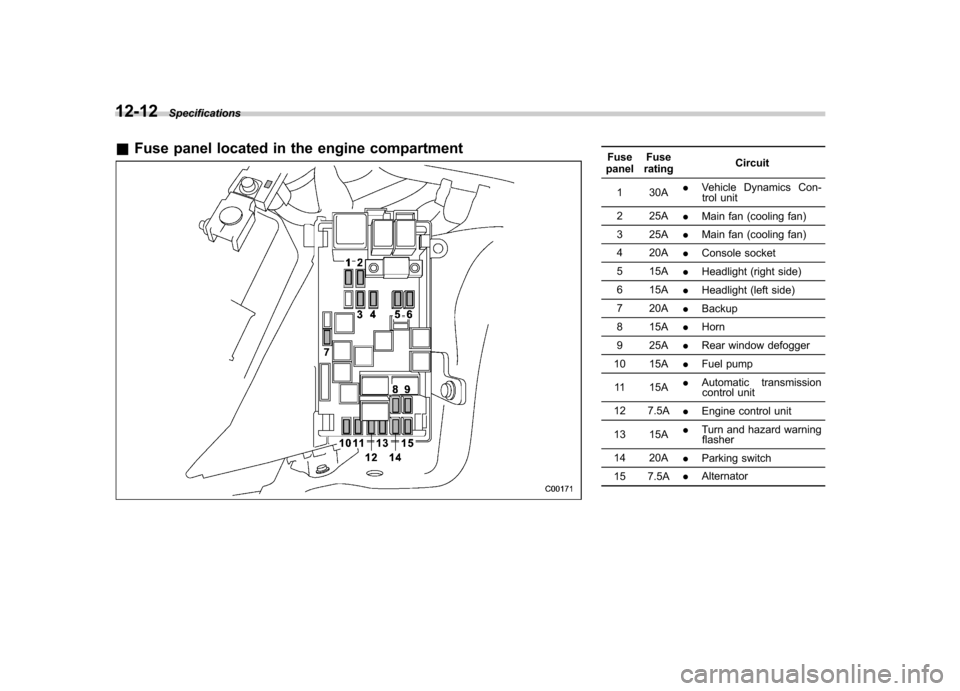
12-12Specifications
&Fuse panel located in the engine compartmentFuse
panel Fuse
rating Circuit
1 30A .
Vehicle Dynamics Con-
trol unit
2 25A .Main fan (cooling fan)
3 25A .Main fan (cooling fan)
4 20A .Console socket
5 15A .Headlight (right side)
6 15A .Headlight (left side)
7 20A .Backup
8 15A .Horn
9 25A .Rear window defogger
10 15A .Fuel pump
11 15A .
Automatic transmission
control unit
12 7.5A .Engine control unit
13 15A .
Turn and hazard warning
flasher
14 20A .Parking switch
15 7.5A .
Alternator
Page 391 of 422
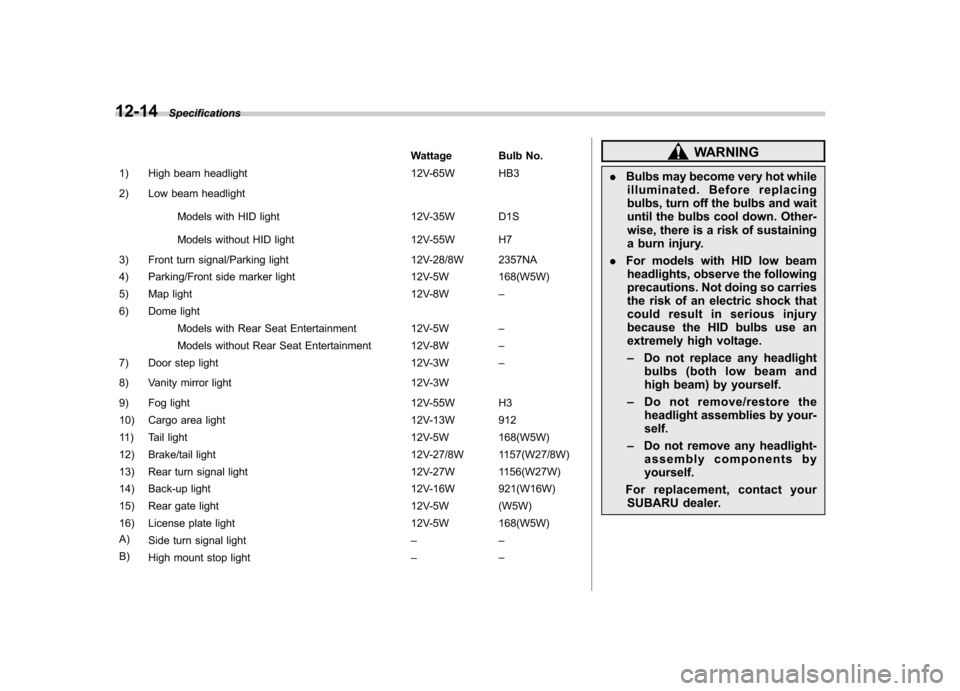
12-14Specifications
Wattage Bulb No.
1) High beam headlight 12V-65W HB3
2) Low beam headlight
Models with HID light 12V-35W D1S
Models without HID light 12V-55W H7
3) Front turn signal/Parking light 12V-28/8W 2357NA
4) Parking/Front side marker light 12V-5W 168(W5W)
5) Map light 12V-8W–
6) Dome light
Models with Rear Seat Entertainment 12V-5W –
Models without Rear Seat Entertainment 12V-8W –
7) Door step light 12V-3W–
8) Vanity mirror light 12V-3W
9) Fog light 12V-55W H3
10) Cargo area light 12V-13W 912
11) Tail light 12V-5W 168(W5W)
12) Brake/tail light 12V-27/8W 1157(W27/8W)
13) Rear turn signal light 12V-27W 1156(W27W)
14) Back-up light 12V-16W 921(W16W)
15) Rear gate light 12V-5W (W5W)
16) License plate light 12V-5W 168(W5W)
A) Side turn signal light ––
B) High mount stop light ––WARNING
. Bulbs may become very hot while
illuminated. Before replacing
bulbs, turn off the bulbs and wait
until the bulbs cool down. Other-
wise, there is a risk of sustaining
a burn injury.
. For models with HID low beam
headlights, observe the following
precautions. Not doing so carries
the risk of an electric shock that
could result in serious injury
because the HID bulbs use an
extremely high voltage. – Do not replace any headlight
bulbs (both low beam and
high beam) by yourself.
– Do not remove/restore the
headlight assemblies by your-self.
– Do not remove any headlight-
assembly components byyourself.
For replacement, contact your SUBARU dealer.
Page 413 of 422
14-4Index
D
Daytime running light system ....................................... 3-27
Differential gear oil
Front ........................................................... 11-16, 12-6
Rear ............................................................ 11-17, 12-6
Dimensions ............................................................... 12-2
Disarming the alarm system ........................................ 2-18
Disc brake pad wear warning indicators ........................ 7-20
Dome light ........................................................ 6-2, 11-43
Door Locks ..................................................................... 2-5
Open warning light ................................................. 3-17
Step light ............................................................. 11-44
Drive belts. ............................................................... 11-14
Driving All-Wheel Drive warning light ................................... 3-18
AWD vehicles .......................................................... 8-4
Car phone/cell phone .................................................. 8
Drinking ..................................................................... 7
Drugs ........................................................................ 7
Foreign countries ..................................................... 8-4
Pets .......................................................................... 8
Snowy and icy roads ................................................ 8-9
Tips.................................................................. 8-2, 8-4
Tired or sleepy. ........................................................... 7
Winter .................................................................... 8-7
E
Electrical system ........................................................ 12-7
Electronic Brake Force Distribution (EBD) system ........................................................... 3-17, 7-22 Emergency Locking Retractor (ELR)
............................. 1-18
Engine Compartment overview ............................................ 11-6
Coolant ....................................................... 11-10, 12-7
Exhaust gas (carbon monoxide) ............................. 6, 8-2
Hood .................................................................... 11-4
Oil ................................................................ 11-7, 12-4Overheating ........................................................... 9-14
Starting .................................................................. 7-7
Stopping ................................................................. 7-8
Exterior care .............................................................. 10-2
F
Flat tires ..................................................................... 9-6
Floor mat ................................................................... 6-13
Fluid level Automatic transmission ......................................... 11-15
Brake .................................................................. 11-18
Power steering ..................................................... 11-17
Fog light
Bulb .................................................................... 11-40
Indicator light ......................................................... 3-21
Switch ................................................................... 3-31
Folding mirror switch ................................................... 3-42
Front Differential gear oil ........................................ 11-16, 12-6
Fog light ...................................................... 3-31, 11-40
Fog light indicator light ............................................ 3-21
Seatbelt pretensioners ............................................ 1-28
Turn signal light .................................................... 11-40
Front seats ................................................................. 1-2