2011 SUBARU TRIBECA headlights
[x] Cancel search: headlightsPage 166 of 422
NOTE
The outside mirror defogger also oper-
ates while the rear window defogger isoperating.Mirrors
Always check that the inside and outside
mirrors are properly adjusted before you
start driving. &
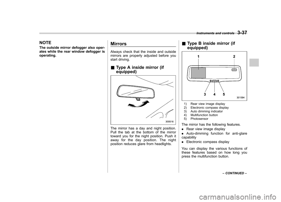
Type A inside mirror (if equipped)
The mirror has a day and night position.
Pull the tab at the bottom of the mirror
toward you for the night position. Push it
away for the day position. The night
position reduces glare from headlights. &
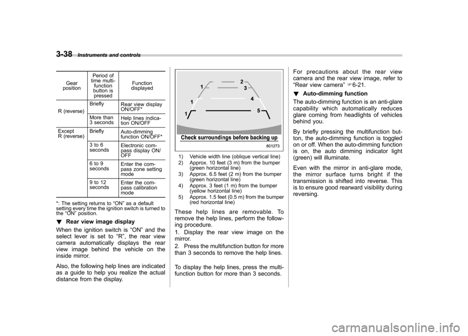
Type B inside mirror (if equipped)
1) Rear view image display
2) Electronic compass display
3) Auto dimming indicator
4) Multifunction button
5) Photosensor
The mirror has the following features. . Rear view image display
. Auto-dimming function for anti-glare
capability. Electronic compass display
You can display the various functions of
these features based on how long you
press the multifunction button. Instruments and controls
3-37
– CONTINUED –
Page 167 of 422
3-38Instruments and controls
Gear
position Period of
time multi-
function
button is pressed Function
displayed
R (reverse) Briefly
Rear view display ON/OFF*
More than
3 seconds Help lines indica-
tion ON/OFF
Except
R (reverse) Briefly
Auto-dimming
function ON/OFF*
3to6 seconds Electronic com-
pass display ON/ OFF
6to9seconds Enter the com-
pass zone setting mode
9to12 seconds Enter the com-
pass calibration mode
*: The setting returns to “ON ”as a default
setting every time the ignition switch is turned tothe “ON ”position.
! Rear view image display
When the ignition switch is “ON ”and the
select lever is set to “R ”, the rear view
camera automatically displays the rear
view image behind the vehicle on the
inside mirror.
Also, the following help lines are indicated
as a guide to help you realize the actual
distance from the display.
1) Vehicle width line (oblique vertical line)
2) Approx. 10 feet (3 m) from the bumper (green horizontal line)
3) Approx. 6.5 feet (2 m) from the bumper (green horizontal line)
4) Approx. 3 feet (1 m) from the bumper (yellow horizontal line)
5) Approx. 1.5 feet (0.5 m) from the bumper (red horizontal line)
These help lines are removable. To
remove the help lines, perform the follow-
ing procedure.
1. Display the rear view image on the
mirror.
2. Press the multifunction button for more
than 3 seconds to remove the help lines.
To display the help lines, press the multi-
function button for more than 3 seconds. For precautions about the rear view
camera and the rear view image, refer to“
Rear view camera ”F 6-21.
! Auto-dimming function
The auto-dimming function is an anti-glare
capability which automatically reduces
glare coming from headlights of vehicles
behind you.
By briefly pressing the multifunction but-
ton, the auto-dimming function is toggled
on or off. When the auto-dimming function
is on, the auto dimming indicator light
(green) will illuminate.
Even with the mirror in anti-glare mode,
the mirror surface turns bright if the
transmission is shifted into reverse. This
is to ensure good rearward visibility duringreversing.
Page 169 of 422

3-40Instruments and controls
& Type C inside mirror (if equipped)
1) Left button
2) Auto dimming indicator
3) Photosensor
4) Right button
This mirror has an anti-glare feature which
automatically reduces glare coming from
headlights of vehicles behind you. It also
contains a built-in compass. . By pressing and releasing the left
button, the automatic dimming function is
toggled on or off. When the automatic
dimming function is on, the auto dimming
indicator light (green) located to the right
of the button will illuminate. . By pressing and releasing the right
button, the compass display is toggled on or off. When the compass is on, an
illuminated compass reading will appear
in the lower part of the mirror.
Even with the mirror in anti-glare mode,
the mirror surface turns bright if the
transmission is shifted into reverse. This
is to ensure good rearward visibility duringreversing. !
Photosensors
The mirror has a photosensor attached on
both the front and back sides. If the glare
from the headlights of vehicles behind you
strikes the mirror, these sensors detect it
and make the reflection surface of the
mirror dimmer to help prevent you from
being blinded. For this reason, use care
not to cover the sensors with stickers, or
other similar items. Periodically wipe the sensors clean using a piece of dry soft
cotton cloth or an applicator. !
Compass calibration
1. For optimum calibration, switch off all
nonessential electrical accessories (rear
window defogger, heater/air conditioning
system, spotlight, etc.) and ensure all
doors are shut.
2. Drive to an open, level area away from
large metallic objects or structures and
make certain the ignition switch is in the“ ON ”position.
3. Press and hold the left button for 3
seconds then release, and the compass
will enter the calibration mode. “CAL ”and
direction will be displayed.
4. Drive slowly in a circle until “CAL ”
disappears from the display (approxi-
mately two or three circles). The compass
is now calibrated.
5. Further calibration may be necessary
should outside influences cause the mirror
to read inaccurately. You will know that
this has occurred if your compass begins
to read in only limited directions. Should
you encounter this situation, return to step
one of the above procedure and recali-
brate the mirror.
Page 333 of 422
Maintenance and serviceRear window wiper blade rubber ....................... 11-32
Battery. .............................................................. 11-34
Fuses ................................................................ 11-35
Main fuse .......................................................... 11-36
Installation of accessories ............................... 11-37
Replacing bulbs ............................................... 11-37
Headlights (models with HID headlights) ........... 11-37
Headlights (models without HID headlights) .. .... 11-37
Parking light (right-hand side) ........................... 11-39
Front turn signal light (right-hand side) ............. 11-40Front fog light
.................................................. 11-40
Rear combination lights ................................... 11-40
Back-up light/Tail light ..................................... 11-41
Rear gate light ................................................. 11-42
License plate light ........................................... 11-42
Dome light ....................................................... 11-43
Map light ......................................................... 11-44
Vanity mirror light ............................................ 11-44
Door step light ................................................. 11-44
Cargo area light ............................................... 11-45
Page 368 of 422
Installation of accessories
Always consult your SUBARU dealer
before installing fog lights or any other
electrical equipment in your vehicle. Such
accessories may cause the electronic
system to malfunction if they are incor-
rectly installed or if they are not suited for
the vehicle.Replacing bulbs
WARNING
Bulbs may become very hot while
illuminated. Before replacing bulbs,
turn off the bulbs and wait until the
bulbs cool down. Otherwise, there is
a risk of sustaining a burn injury.
CAUTION
Replace any bulb only with a new
bulb of the specified wattage. Using
a bulb of different wattage could
result in a fire. For the specified
wattage of each bulb, refer to “Bulb
chart ”F 12-13.
& Headlights (models with HID headlights)
WARNING
High-intensity-discharge (HID) bulbs
are used for the low beams of the
headlights. These HID bulbs use an
extremely high voltage. To avoid the
risk of an electric shock that could
result in serious injury, observe the following precautions. .
Do not replace any headlight
bulbs (both low beam and high
beam) by yourself.
. Do not remove/restore the head-
light assemblies by yourself.
. Do not remove any headlight-
assembly components by your-self.
For replacement, contact your
SUBARU dealer.
& Headlights (models without
HID headlights)
CAUTION
Halogen headlight bulbs become
very hot while in use. If you touch
the bulb surface with bare hands or
greasy gloves, fingerprints or
grease on the bulb surface will
develop into hot spots, causing the
bulb to break. If there are finger
prints or grease on the bulb surface,
wipe them away with a soft cloth
moistened with alcohol. Maintenance and service
11-37
– CONTINUED –
Page 391 of 422
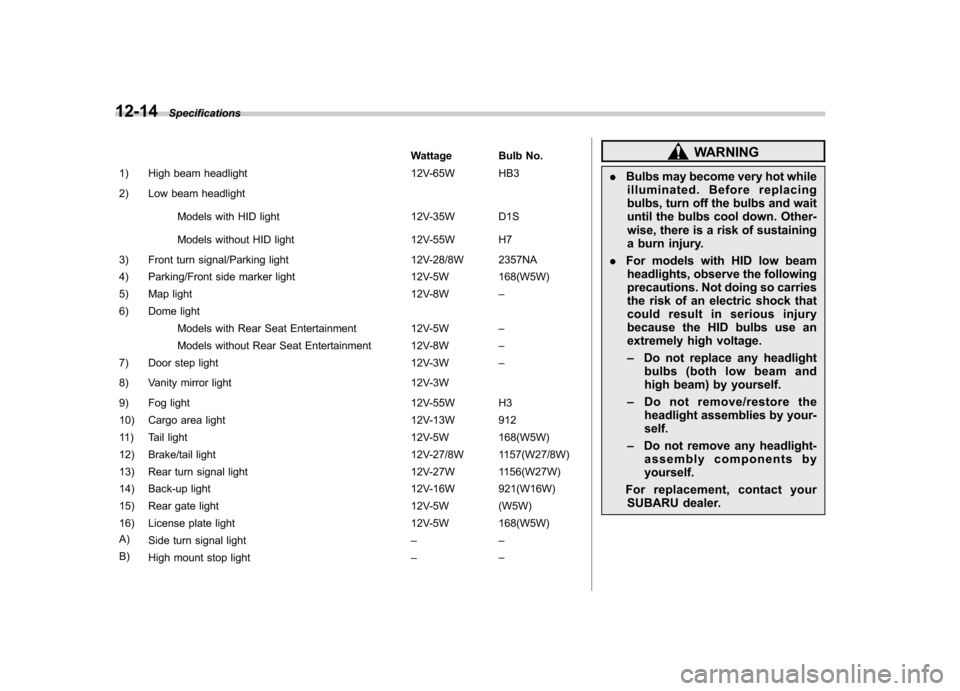
12-14Specifications
Wattage Bulb No.
1) High beam headlight 12V-65W HB3
2) Low beam headlight
Models with HID light 12V-35W D1S
Models without HID light 12V-55W H7
3) Front turn signal/Parking light 12V-28/8W 2357NA
4) Parking/Front side marker light 12V-5W 168(W5W)
5) Map light 12V-8W–
6) Dome light
Models with Rear Seat Entertainment 12V-5W –
Models without Rear Seat Entertainment 12V-8W –
7) Door step light 12V-3W–
8) Vanity mirror light 12V-3W
9) Fog light 12V-55W H3
10) Cargo area light 12V-13W 912
11) Tail light 12V-5W 168(W5W)
12) Brake/tail light 12V-27/8W 1157(W27/8W)
13) Rear turn signal light 12V-27W 1156(W27W)
14) Back-up light 12V-16W 921(W16W)
15) Rear gate light 12V-5W (W5W)
16) License plate light 12V-5W 168(W5W)
A) Side turn signal light ––
B) High mount stop light ––WARNING
. Bulbs may become very hot while
illuminated. Before replacing
bulbs, turn off the bulbs and wait
until the bulbs cool down. Other-
wise, there is a risk of sustaining
a burn injury.
. For models with HID low beam
headlights, observe the following
precautions. Not doing so carries
the risk of an electric shock that
could result in serious injury
because the HID bulbs use an
extremely high voltage. – Do not replace any headlight
bulbs (both low beam and
high beam) by yourself.
– Do not remove/restore the
headlight assemblies by your-self.
– Do not remove any headlight-
assembly components byyourself.
For replacement, contact your SUBARU dealer.