2011 SUBARU IMPREZA WRX door lock
[x] Cancel search: door lockPage 252 of 458
&Map lights
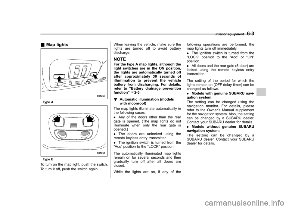
Type A
Type B
To turn on the map light, push the switch.
To turn it off, push the switch again. When leaving the vehicle, make sure the
lights are turned off to avoid batterydischarge.
NOTE
For the type A map lights, although the
light switches are in the ON position,
the lights are automatically turned off
after approximately 30 seconds of
illumination to prevent the vehicle
battery from discharging. For details,
refer to “Battery drainage prevention
function ”F 2-5.
! Automatic illumination (models
with moonroof)
The map lights illuminate automatically in
the following cases. . Any of the doors other than the rear
gate is opened. (The map lights do not
illuminate when only the rear gate isopened.) . The doors are unlocked using the
remote keyless entry transmitter.. The ignition switch is turned from the
“ Acc ”position to the “LOCK ”position.
The automatically illuminated map lights
remain on for several seconds and then
gradually turn off after all doors areclosed.
While the lights are on, if any of the following operations are performed, the
map lights turn off immediately. .
The ignition switch is turned from the
“ LOCK ”position to the “Acc ”or “ON ”
position.. All doors and the rear gate (5-door) are
locked using the remote keyless entry
transmitter.
The setting of the period for which the
lights remain on (OFF delay timer) can be
changed as follows. . Models with genuine SUBARU navi-
gation system:
The setting can be changed using the
navigation monitor. For details, please
refer to the Owner ’s Manual supplement
for the navigation system. Also, the setting
can be changed by a SUBARU dealer.
Contact your SUBARU dealer for details. . Models without genuine SUBARU
navigation system:
The setting can be changed by a
SUBARU dealer. Contact your SUBARU
dealer for details. Interior equipment
6-3
Page 268 of 458
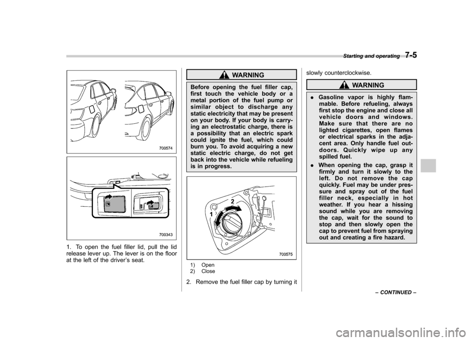
1. To open the fuel filler lid, pull the lid
release lever up. The lever is on the floor
at the left of the driver’s seat.
WARNING
Before opening the fuel filler cap,
first touch the vehicle body or a
metal portion of the fuel pump or
similar object to discharge any
static electricity that may be present
on your body. If your body is carry-
ing an electrostatic charge, there is
a possibility that an electric spark
could ignite the fuel, which could
burn you. To avoid acquiring a new
static electric charge, do not get
back into the vehicle while refueling
is in progress.
1) Open
2) Close
2. Remove the fuel filler cap by turning it slowly counterclockwise.
WARNING
. Gasoline vapor is highly flam-
mable. Before refueling, always
first stop the engine and close all
vehicle doors and windows.
Make sure that there are no
lighted cigarettes, open flames
or electrical sparks in the adja-
cent area. Only handle fuel out-
doors. Quickly wipe up any
spilled fuel.
. When opening the cap, grasp it
firmly and turn it slowly to the
left. Do not remove the cap
quickly. Fuel may be under pres-
sure and spray out of the fuel
filler neck, especially in hot
weather. If you hear a hissing
sound while you are removing
the cap, wait for the sound to
stop and then slowly open the
cap to prevent fuel from spraying
out and creating a fire hazard. Starting and operating
7-5
– CONTINUED –
Page 269 of 458
7-6Starting and operating
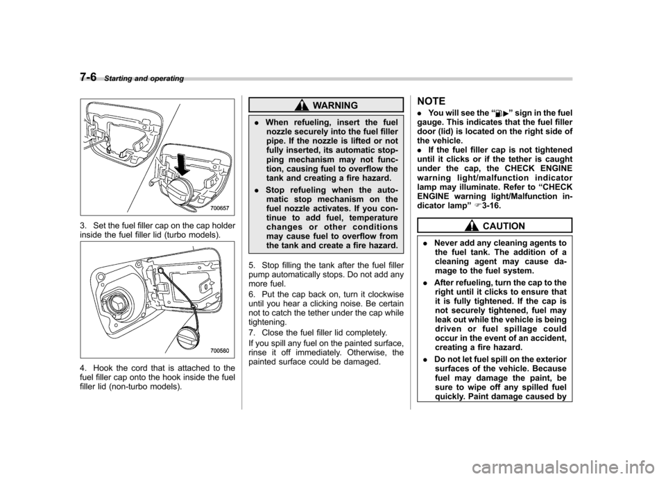
3. Set the fuel filler cap on the cap holder
inside the fuel filler lid (turbo models).
4. Hook the cord that is attached to the
fuel filler cap onto the hook inside the fuel
filler lid (non-turbo models).
WARNING
. When refueling, insert the fuel
nozzle securely into the fuel filler
pipe. If the nozzle is lifted or not
fully inserted, its automatic stop-
ping mechanism may not func-
tion, causing fuel to overflow the
tank and creating a fire hazard.
. Stop refueling when the auto-
matic stop mechanism on the
fuel nozzle activates. If you con-
tinue to add fuel, temperature
changes or other conditions
may cause fuel to overflow from
the tank and create a fire hazard.
5. Stop filling the tank after the fuel filler
pump automatically stops. Do not add any
more fuel.
6. Put the cap back on, turn it clockwise
until you hear a clicking noise. Be certain
not to catch the tether under the cap whiletightening.
7. Close the fuel filler lid completely.
If you spill any fuel on the painted surface,
rinse it off immediately. Otherwise, the
painted surface could be damaged. NOTE .
You will see the “”sign in the fuel
gauge. This indicates that the fuel filler
door (lid) is located on the right side of
the vehicle.. If the fuel filler cap is not tightened
until it clicks or if the tether is caught
under the cap, the CHECK ENGINE
warning light/malfunction indicator
lamp may illuminate. Refer to “CHECK
ENGINE warning light/Malfunction in-
dicator lamp ”F 3-16.
CAUTION
. Never add any cleaning agents to
the fuel tank. The addition of a
cleaning agent may cause da-
mage to the fuel system.
. After refueling, turn the cap to the
right until it clicks to ensure that
it is fully tightened. If the cap is
not securely tightened, fuel may
leak out while the vehicle is being
driven or fuel spillage could
occur in the event of an accident,
creating a fire hazard.
. Do not let fuel spill on the exterior
surfaces of the vehicle. Because
fuel may damage the paint, be
sure to wipe off any spilled fuel
quickly. Paint damage caused by
Page 275 of 458
7-12Starting and operating
& Entering the vehicle while it
is running via remote start
1. Unlock the vehicle doors using the
remote keyless entry system. If the vehi-cle ’s doors are unlocked manually using
the key, the vehicle ’s alarm system will
trigger and the remote engine start system
will turn off. Inserting the key into the
ignition switch and turning it to the “ON ”
position or pressing the unlock button “
”
on the remote keyless entry transmitter
will disarm the alarm system. Refer to“ Alarm system ”F 2-16.
2. Enter the vehicle. Do not depress the
brake pedal.
3. Insert the key into the ignition switch
and turn to the “ON ”position. If the ignition
switch is accidentally turned to the“ START ”position, the system ’s “starter
anti-grind ”feature will prevent the starter
from re-cranking.
4. Depress the brake pedal. The remote
starter disengages, the vehicle ’s power
window features are re-enabled and the
vehicle will operate normally.
& Entering the vehicle follow-
ing remote engine start shut-down
An alarm trigger may occur if the vehicle is
opened by the remote keyless entry transmitter within a few seconds immedi-
ately following remote engine start shut-down.
& Pre-heating or pre-cooling
the interior of the vehicle
Before exiting the vehicle, set the tem-
perature controls to the desired setting
and operation. After the system starts the
vehicle, the heater or air-conditioning will
activate and heat or cool the interior to
your setting. & Service mode
In service mode, the remote start function
is temporarily disabled to prevent the
system from unexpectedly starting the
engine while being serviced. ! To engage the service mode
Turn the ignition switch to the “ON ”
position, depress and hold the brake
pedal, then press and release the “
”
button on the remote engine start trans-
mitter three times. The system will pause
for 1 second and then flash the turn signal
lights and honk the horn three times
indicating that the system is in service
mode. When attempting to activate the
remote start system while in service
mode, the turn signal lights will flash and
the horn will honk two times and will not start. !
To disengage the service mode
Turntheignitionswitchtothe “ON ”
position, depress and hold the brake
pedal, then press and release the “
”
button on the remote engine start trans-
mitter three times. The system will pause
for 1 second and flash the turn signal
lights once indicating that the system has
exited service mode.
NOTE
When taking your vehicle in for service,
it is recommended that you inform the
service personnel that your vehicle is
equipped with a remote engine startsystem. & Remote engine start trans-
mitter programming and pro-
grammable feature option
New transmitters can be programmed to
the remote engine start system in the
event that remote engine start transmitters
are lost, stolen or damaged. The remote
engine start system also has one pro-
grammable feature that can be adjusted
for user preference.
The remote engine start system can be
programmed to either make an audible
horn chirp upon remote start activation or
Page 276 of 458

not. Remote engine start transmitter pro-
gramming and feature programming can
be adjusted using the following procedure.
1. Open the driver’s door (the driver ’s
door must remain opened throughout the
entire process).
2. Insert the key into the vehicle ’s ignition
switch and turn to the “ON ”position.
3. Locate the small black programming
button behind the fuse box cover, on the
driver ’s side left under the dashboard
panel.
4. Press and hold the black programming
button for 10 to 15 seconds. The horn will
honk and the turn signal lights will flash
three times to indicate that the system has
entered programming mode. At this point
you can proceed to either step 5 or step 6.
5. To program a remote engine start
transmitter: press and release the “
”
button on each transmitter. The horn will
honk and the turn signal lights will flash
one time to indicate a successful trans-
mitter learn each time the “
”button is
pressed. You can program up to eight transmitters.
6. To toggle the Horn Confirmation chirps
ON/OFF: depress and release the brake
pedal to toggle the feature. The horn will
chirp and the turn signal lights will flash
one time to indicate Confirmation Horn
Chirps are “OFF ”. The horn will honk and the turn signal lights will flash 2 times to
indicate Confirmation Horn Chirps are“
ON ”. Depressing the brake pedal repeat-
edly will toggle the feature ON or OFF
each time.
7. To exit the remote engine start trans-
mitter and feature programming mode,
turn the ignition switch to the “LOCK ”
position, remove the key from the ignition
switch and test operation of the remote
engine start transmitter(s) and horn con-
firmation feature.
& System maintenance
! Changing the batteries
CAUTION
. Do not let dust, oil or water get on
or in the remote engine start
transmitter when replacing the
battery.
. Be careful not to damage the
printed circuit board in the re-
mote engine start transmitter
when replacing the battery.
. Be careful not to allow children to
touch the battery and any re-
moved parts; children could
swallow them.
. There is a danger of explosion if an incorrect replacement battery
is used. Replace only with the
same or equivalent type of bat-
tery.
. Batteries should not be exposed
to excessive heat such as sun-
shine, fire or the like.
The two 3-volt lithium batteries (modelCR-1220 ) supplied in your remote engine
start transmitter should last approximately
3 years, depending on usage. When the
batteries begin to weaken, you will notice
a decrease in range (distance from the
vehicle that your remote engine start
system operates). Follow the instructions
below to change the remote engine start
transmitter batteries.
Starting and operating 7-13
– CONTINUED –
Page 319 of 458

8-8Driving tips
Winter driving
&Operation during cold weather
Carry some emergency equipment, such
as a window scraper, a bag of sand,
flares, a small shovel and jumper cables.
Check the battery and cables. Cold
temperatures reduce battery capacity.
The battery must be in good condition to
provide enough power for cold winterstarts.
It normally takes longer to start the engine
in very cold weather conditions. Use an
engine oil of a proper grade and viscosity
for cold weather. Using heavy summer oil
will make it harder to start the engine.
Keep the door locks from freezing by squirting them with deicer or glycerin.
Forcing a frozen door open may damage
or separate the rubber weather strips
around the door. If the door is frozen,
use hot water to melt the ice, and after-
wards thoroughly wipe the water away.
Use a windshield washer fluid that con-
tains an antifreeze solution. Do not use
engine antifreeze or other substitutes
because they may damage the paint of
the vehicle.
SUBARU Windshield Washer Fluid con-
tains 58.5% methyl alcohol and 41.5%
surfactant, by volume. Its freezing tem-
perature varies according to how much it
is diluted, as indicated in the followingtable.
Washer Fluid Con- centration Freezing Temperature
30% 10.4 8F( �12 8C)
50% �48F( �20 8C)
100% �
49 8F( �45 8C)
In order to prevent freezing of washer
fluid, check the freezing temperatures in
the table above when adjusting the fluid
concentration to the outside temperature.
If you fill the reservoir tank with a fluid with
a different concentration from the one used previously, purge the old fluid from
the piping between the reservoir tank and
washer nozzles by operating the washer
for a certain period of time. Otherwise, if
the concentration of the fluid remaining in
the piping is too low for the outside
temperature, it may freeze and block thenozzles.
CAUTION
. Adjust the washer fluid concen-
tration appropriately for the out-
side temperature. If the concen-
tration is inappropriate, sprayed
washer fluid may freeze on the
windshield and obstruct your
view, and the fluid may freeze in
the reservoir tank.
. State or local regulations on
volatile organic compounds may
restrict the use of methanol, a
common windshield washer anti-
freeze additive. Washer fluids
containing non-methanol anti-
freeze agents should be used
only if they provide cold weather
protection without damaging
your vehicle ’s paint, wiper blades
or washer system.
Page 333 of 458
9-6In case of emergency
B) Except models with 16-inch wheel tires
The jack handle is stored under the floor of
the trunk (4-door) or the cargo area (5-
door). The jack and towing hook are
stored in the tool bucket that is located in
the recess of the spare tire wheel.
Also, the tools in the tool bag can be
stored in the tool bucket as illustrated.
For how to use the jack, refer to “Flat tires ”
F 9-6. Flat tires
If you have a flat tire while driving, never
brake suddenly; keep driving straight
ahead while gradually reducing speed.
Then slowly pull off the road to a safeplace. &
Changing a flat tire
WARNING
. Do not jack up the vehicle on an
incline or a loose road surface.
The jack can come out of the
jacking point or sink into the
ground and this can result in a
severe accident.
. Use only the jack provided with
your vehicle. The jack supplied
with the vehicle is designed only
for changing a tire. Never get
under the vehicle while support-
ing the vehicle with this jack. .
Always turn off the engine before
raising the flat tire off the ground
using the jack. Never swing or
push the vehicle supported with
the jack. The jack can come out
of the jacking point due to a jolt
and this can result in a severeaccident.
1. Park on a hard, level surface, when-
ever possible, then stop the engine.
2. Set the parking brake securely and
shift the shift lever in reverse (MT models)
or the select lever to the “P ” (Park)
position (AT models).
3. Turn on the hazard warning flasher
and have everyone get out of the vehicle.
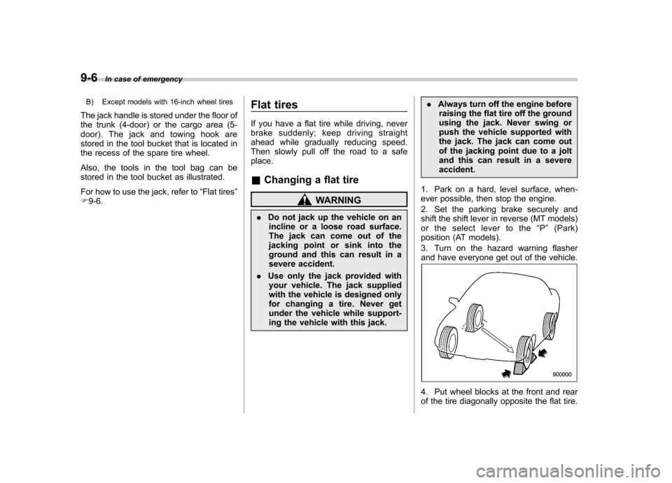
4. Put wheel blocks at the front and rear
of the tire diagonally opposite the flat tire.
Page 334 of 458
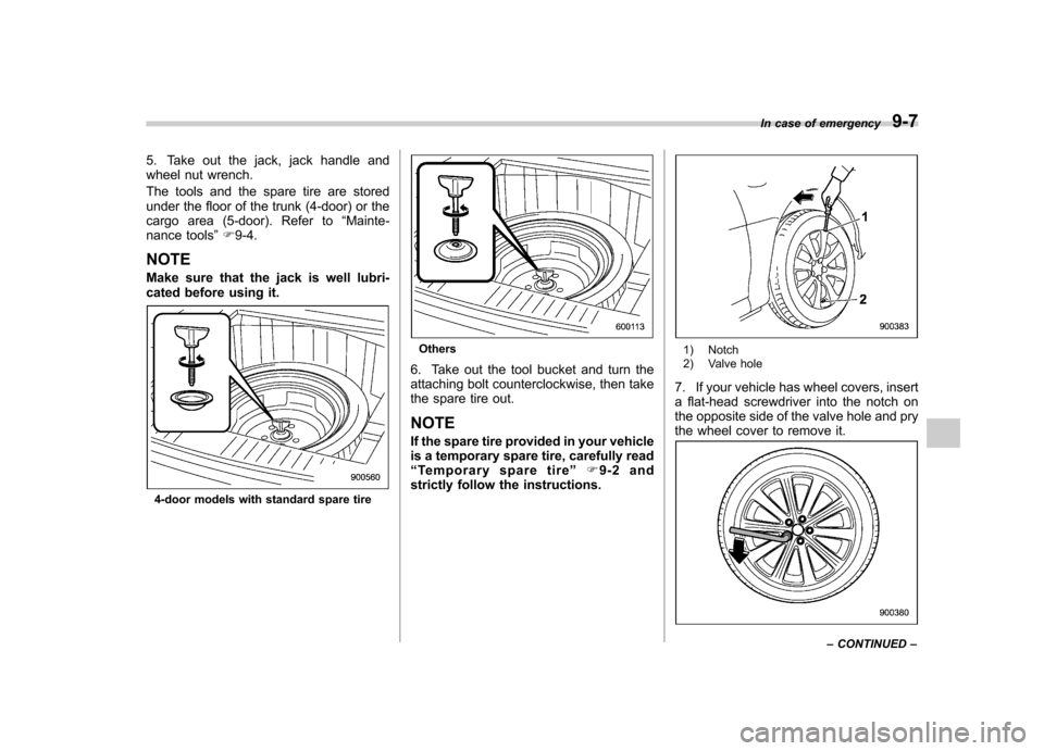
5. Take out the jack, jack handle and
wheel nut wrench.
The tools and the spare tire are stored
under the floor of the trunk (4-door) or the
cargo area (5-door). Refer to“Mainte-
nance tools ”F 9-4.
NOTE
Make sure that the jack is well lubri-
cated before using it.
4-door models with standard spare tire
Others
6. Take out the tool bucket and turn the
attaching bolt counterclockwise, then take
the spare tire out. NOTE
If the spare tire provided in your vehicle
is a temporary spare tire, carefully read“ Temporary spare tire ”F9-2 and
strictly follow the instructions.1) Notch
2) Valve hole
7. If your vehicle has wheel covers, insert
a flat-head screwdriver into the notch on
the opposite side of the valve hole and pry
the wheel cover to remove it.
In case of emergency 9-7
– CONTINUED –