2011 SUBARU IMPREZA WRX ABS
[x] Cancel search: ABSPage 301 of 458
7-38Starting and operating
road with a snowy, gravel-covered, or
otherwise slippery surface .extrication of the vehicle when its
wheels are stuck in mud or deep snow
When the switch is pressed during engine
operation, the Vehicle Dynamics Control
OFF indicator light on the combination
meter illuminates. The Vehicle Dynamics
Control system will be deactivated and the
vehicle will behave like a model not
equipped with the Vehicle Dynamics Con-
trol system. When the switch is pressed
again to reactivate the Vehicle Dynamics
Control system, the Vehicle Dynamics
Control OFF indicator light turns off.
With the Vehicle Dynamics Control system
deactivated, traction and stability en-
hancement offered by Vehicle Dynamics
Control system is unavailable. Therefore
you should not deactivate the Vehicle
Dynamics Control system except under
above-mentioned situations. NOTE . The Vehicle Dynamics Control sys-
tem will be activated automatically
when the engine is started.. If the switch is held down for 10
seconds or longer, the indicator light
turns off, the Vehicle Dynamics Control
system is activated, and the system
ignores any further pressing of the switch. To make the switch usable
again, turn the ignition switch to the“
LOCK ”position and restart the en-
gine.. When the switch is pressed to
deactivate the Vehicle Dynamics Con-
trol system, the vehicle ’s running per-
formance is comparable with that of a
vehicle that does not have a Vehicle
Dynamics Control system. Do not de-
activate the Vehicle Dynamics Control
system except when absolutely neces-
sary.. Even when the Vehicle Dynamics
Control system is deactivated, compo-
nents of the brake control system may
still activate. When the brake control
system is activated, the Vehicle Dy-
namics Control operation indicator
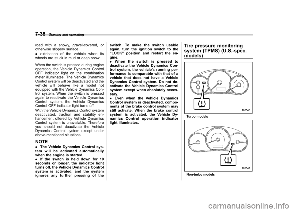
light illuminates. Tire pressure monitoring
system (TPMS) (U.S.-spec.
models)
Turbo models
Non-turbo models
Page 306 of 458
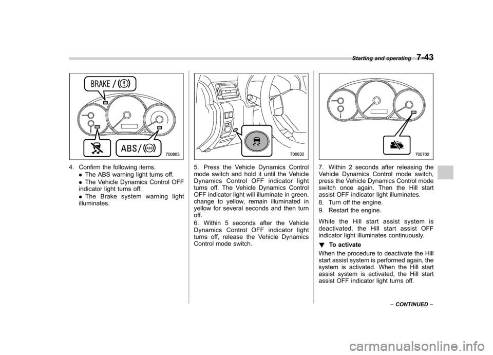
4. Confirm the following items..The ABS warning light turns off.
. The Vehicle Dynamics Control OFF
indicator light turns off. . The Brake system warning light
illuminates.5. Press the Vehicle Dynamics Control
mode switch and hold it until the Vehicle
Dynamics Control OFF indicator light
turns off. The Vehicle Dynamics Control
OFF indicator light will illuminate in green,
change to yellow, remain illuminated in
yellow for several seconds and then turn
off.
6. Within 5 seconds after the Vehicle
Dynamics Control OFF indicator light
turns off, release the Vehicle Dynamics
Control mode switch.7. Within 2 seconds after releasing the
Vehicle Dynamics Control mode switch,
press the Vehicle Dynamics Control mode
switch once again. Then the Hill start
assist OFF indicator light illuminates.
8. Turn off the engine.
9. Restart the engine.
While the Hill start assist system is
deactivated, the Hill start assist OFF
indicator light illuminates continuously. ! To activate
When the procedure to deactivate the Hill
start assist system is performed again, the
system is activated. When the Hill start
assist system is activated, the Hill start
assist OFF indicator light turns off. Starting and operating
7-43
– CONTINUED –
Page 320 of 458
!Before driving your vehicle
Before entering the vehicle, remove any
snow or ice from your shoes because that
could make the pedals slippery and
driving dangerous.
While warming up the vehicle before
driving, check that the accelerator pedal,
brake pedal, and all other controls operate
smoothly.
Clear away ice and snow that has
accumulated under the fenders to avoid
making steering difficult. During severe
winter driving, stop when and where it is
safe to do so and check under the fenders
periodically. ! Parking in cold weather
Do not use the parking brake when
parking for long periods in cold weather
since it could freeze in that position.
Instead, you should observe the followingtips.
1. Place the shift lever in “1 ” or “R ”for MT
models, or the select lever in “P ” for AT
models.
2. Use tire stops under the tires to
prevent the vehicle from moving.
When the vehicle is parked in snow or
when it snows, raise the wiper blades off
the glass to prevent damage to them. When the vehicle has been left parked
after use on roads heavily covered with
snow, or has been left parked during a
snowstorm, icing may develop on the
brake system, which could cause poor
braking action. Check for snow or ice
buildup on the suspension, disc brakes
and brake hoses underneath the vehicle.
If there is caked snow or ice, remove it,
being careful not to damage the disc
brakes and brake hoses and ABS har-ness.
WARNING
Snow can trap dangerous exhaust
gases under your vehicle. Keep
snow clear of the exhaust pipe and
from around your vehicle if you park
the vehicle in snow with the enginerunning.
! Refueling in cold weather
To help prevent moisture from forming in
the fuel system and the risk of its freezing,
use of an antifreeze additive in the fuel
tank is recommended during cold weather.
Use only additives that are specifically
designed for this purpose. When an
antifreeze additive is used, its effect lasts
longer if the tank is refilled whenever the
fuel level reaches half empty. If your SUBARU is not going to be used
for an extended period, it is best to have
the fuel tank filled to capacity. &
Driving on snowy and icy roads
To prevent skidding and slipping, avoid
sudden braking, abrupt acceleration, high-
speed driving, and sharp turning when
driving on snowy or icy roads.
Always maintain ample distance between
your vehicle and the vehicle ahead of you
to avoid the need for sudden braking.
To supplement the foot brake, use the
engine brake effectively to control the
vehicle speed. (Shift into a lower gear
when necessary.)
Avoid shifting down abruptly. Such beha-
vior can cause the wheels to lock, possibly
leading to loss of vehicle control.
An anti-lock brake system (ABS) en-
hances your vehicle ’s braking perfor-
manceonsnowyandicyroads.For
information on braking on slippery sur-
faces, refer to “ABS (Anti-lock Brake
System) ”F 7-32 and “Vehicle Dynamics
Control system ”F 7-34.
WARNING
Do not use the cruise control on
slippery roads such as snowy or icy Driving tips
8-9
– CONTINUED –
Page 368 of 458
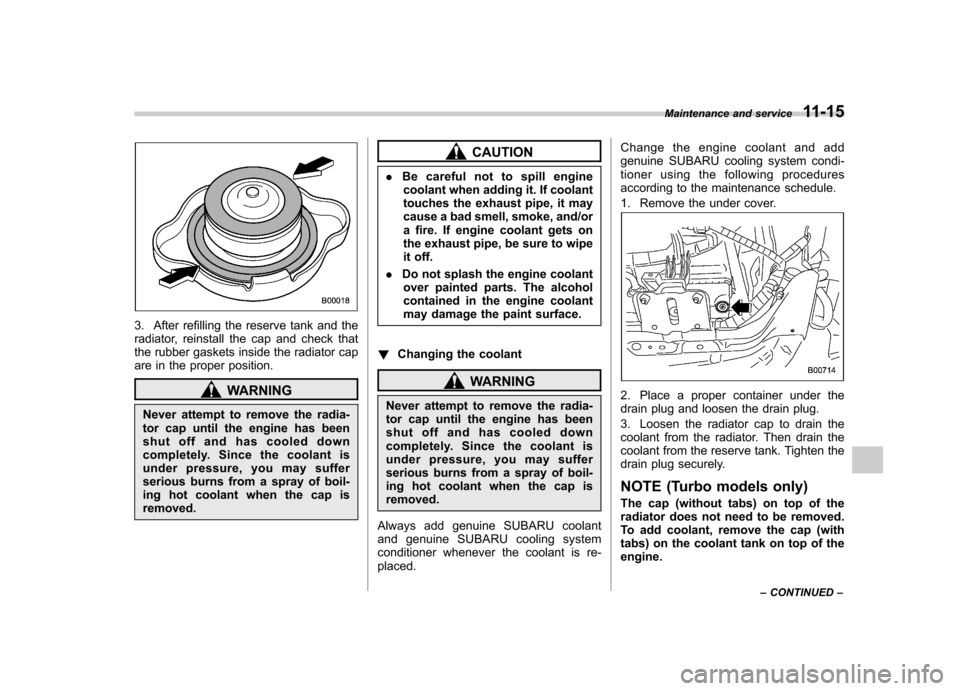
3. After refilling the reserve tank and the
radiator, reinstall the cap and check that
the rubber gaskets inside the radiator cap
are in the proper position.
WARNING
Never attempt to remove the radia-
tor cap until the engine has been
shut off and has cooled down
completely. Since the coolant is
under pressure, you may suffer
serious burns from a spray of boil-
ing hot coolant when the cap isremoved.
CAUTION
. Be careful not to spill engine
coolant when adding it. If coolant
touches the exhaust pipe, it may
cause a bad smell, smoke, and/or
a fire. If engine coolant gets on
the exhaust pipe, be sure to wipe
it off.
. Do not splash the engine coolant
over painted parts. The alcohol
contained in the engine coolant
may damage the paint surface.
! Changing the coolant
WARNING
Never attempt to remove the radia-
tor cap until the engine has been
shut off and has cooled down
completely. Since the coolant is
under pressure, you may suffer
serious burns from a spray of boil-
ing hot coolant when the cap is removed.
Always add genuine SUBARU coolant
and genuine SUBARU cooling system
conditioner whenever the coolant is re-placed. Change the engine coolant and add
genuine SUBARU cooling system condi-
tioner using the following procedures
according to the maintenance schedule.
1. Remove the under cover.2. Place a proper container under the
drain plug and loosen the drain plug.
3. Loosen the radiator cap to drain the
coolant from the radiator. Then drain the
coolant from the reserve tank. Tighten the
drain plug securely.
NOTE (Turbo models only)
The cap (without tabs) on top of the
radiator does not need to be removed.
To add coolant, remove the cap (with
tabs) on the coolant tank on top of theengine.Maintenance and service
11-15
– CONTINUED –
Page 379 of 458
11-26Maintenance and service
clean water. For safety, when
performing this work, wearing
eye protection is advisable.
. Brake fluid absorbs moisture
from the air. Any absorbed moist-
ure can cause a dangerous loss
of braking performance.
. If the vehicle requires frequent
refilling, there may be a leak. If
you suspect a problem, have the
vehicle checked at your SUBARU
dealer.
CAUTION
. When adding brake fluid, be care-
ful not to allow any dirt into the
reservoir.
. Never splash the brake fluid over
painted surfaces or rubber parts.
Alcohol contained in the brake
fluid may damage them.
. Be careful not to spill brake fluid
when adding it. If brake fluid
touches the exhaust pipe, it may
cause a bad smell, smoke, and/or
a fire. If brake fluid gets on the
exhaust pipe, be sure to wipe itoff. &
Recommended brake fluid
Refer to “Fluids ”F 12-9.
CAUTION
Never use different brands of brake
fluid together. Also, avoid mixing
DOT 3 and DOT 4 brake fluids even if
they are the same brand. Clutch fluid (MT models) &
Checking the fluid level
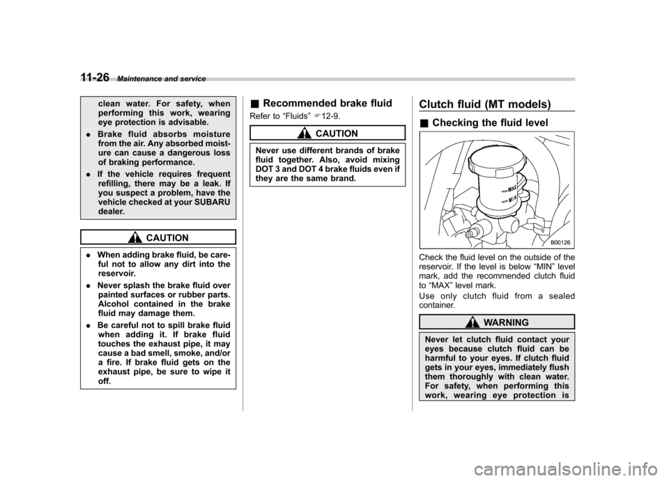
Check the fluid level on the outside of the
reservoir. If the level is below “MIN ”level
mark, add the recommended clutch fluidto “MAX ”level mark.
Use only clutch fluid from a sealed
container.
WARNING
Never let clutch fluid contact your
eyes because clutch fluid can be
harmful to your eyes. If clutch fluid
gets in your eyes, immediately flush
them thoroughly with clean water.
For safety, when performing this
work, wearing eye protection is
Page 380 of 458
advisable.
CAUTION
. Clutch fluid absorbs moisture
from the air. Any absorbed moist-
ure can cause improper clutchoperation.
. If the vehicle requires frequent
refilling, there may be a leak. If
you suspect a problem, have the
vehicle checked at your SUBARU
dealer.
. When clutch fluid is added, be
careful not to allow any dirt into
the tank.
. Never splash the clutch fluid over
painted surfaces or rubber parts.
Alcohol contained in the clutch
fluid may damage them.
. Be careful not to spill clutch fluid
when adding it. If clutch fluid
touches the exhaust pipe, it may
cause a bad smell, smoke, and/or
a fire. If clutch fluid gets on the
exhaust pipe, be sure to wipe itoff. &
Recommended clutch fluid
Refer to “Fluids ”F 12-9.CAUTION
Never use different brands of clutch
fluid together. Also, avoid mixing
DOT 3 and DOT 4 brake fluids even if
they are the same brand. Brake booster
If the brake booster does not operate as
described in the following, have it checked
by your SUBARU dealer.
1. With the engine off, depress the brake
pedal several times, applying the same
pedal force each time. The distance the
pedal travels should not vary.
2. With the brake pedal depressed, start
the engine. The pedal should move
slightly down to the floor.
3. With the brake pedal depressed, stop
the engine and keep the pedal depressed
for 30 seconds. The pedal height should
not change.
4. Start the engine again and run for
approximately one minute then turn it off.
Depress the brake pedal several times to
check the brake booster. The brake
booster operates properly if the pedal
stroke decreases with each depression. NOTE
For vehicles equipped with the brake
assist system, when you depress the
brake pedal strongly or suddenly, the
following phenomena occur. However,
even though these occur, they do not
indicate any malfunctions, and the
brake assist system is operating prop-Maintenance and service
11-27
– CONTINUED –
Page 422 of 458

Fuse
panel Fuse
rating Circuit
16 10A .Illumination
17 15A .Seat heaters
18 10A .Back-up light
19 Empty
20 10A .Accessory power outlet
(instrument panel)
21 7.5A .Starter relay
22 15A .Air conditioner
. Rear window defogger
relay coil
23 15A .Rear wiper
. Rear window washer
24 15A .Audio unit
25 15A .SRS airbag system
26 7.5A .Power window relay
. Radiator main fan relay
27 15A .Blower fan
28 15A .Blower fan
29 15A .Fog light
30 30A .Front wiper
31 7.5A .Auto air conditioner unit
. Integrated unit Fuse
panel Fuse
rating Circuit
32 Empty
33 7.5A .ABS/Vehicle Dynamics
Control unit Specifications
12-13
– CONTINUED –
Page 423 of 458
12-14Specifications
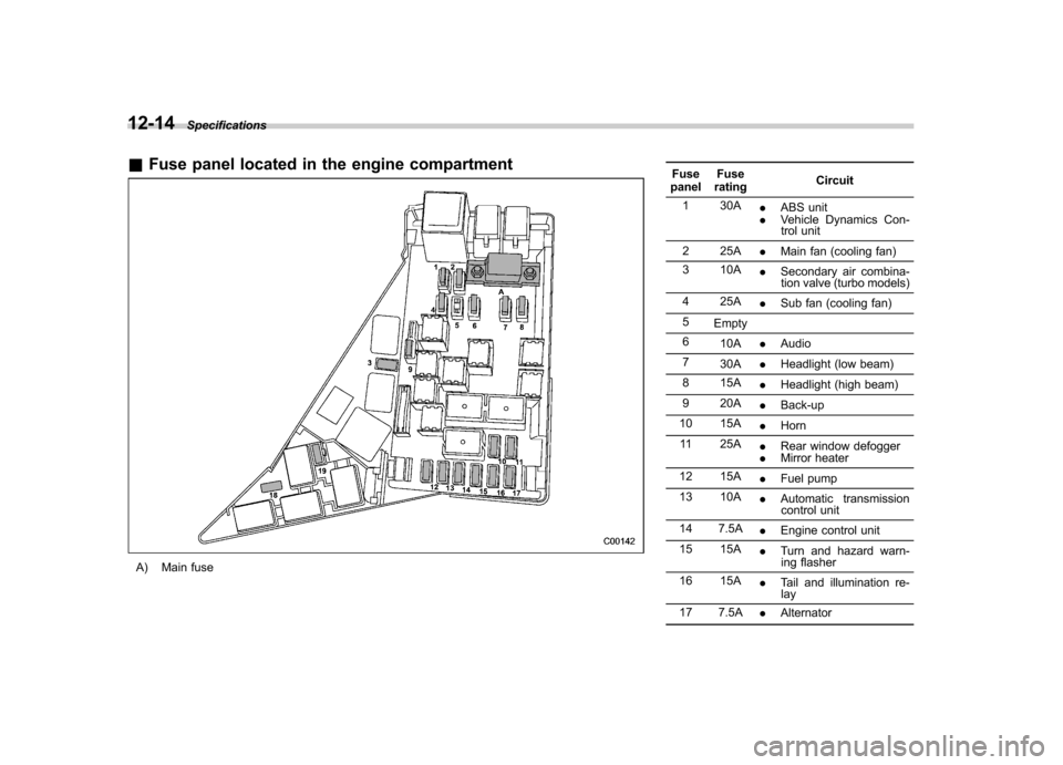
&Fuse panel located in the engine compartment
A) Main fuse Fuse
panel Fuse
rating Circuit
1 30A .ABS unit
. Vehicle Dynamics Con-
trol unit
2 25A .Main fan (cooling fan)
3 10A .Secondary air combina-
tion valve (turbo models)
4 25A .Sub fan (cooling fan)
5 Empty
6 10A .Audio
7 30A .Headlight (low beam)
8 15A .Headlight (high beam)
9 20A .Back-up
10 15A .Horn
11 25A .Rear window defogger
. Mirror heater
12 15A .Fuel pump
13 10A .Automatic transmission
control unit
14 7.5A .Engine control unit
15 15A .Turn and hazard warn-
ing flasher
16 15A .Tail and illumination re-
lay
17 7.5A .Alternator