2011 SUBARU IMPREZA WRX warning lights
[x] Cancel search: warning lightsPage 125 of 458
3-6Instruments and controls
Meters and gauges NOTE
Liquid-crystal displays are used in
some of the meters and gauges on
the combination meter. You will find
their indications hard to see if you wear
polarized glasses. &Combination meter illumina- tion
When the ignition switch is turned to the “ ON ”position, the various parts of the
combination meter are illuminated in the
following sequence:
Turbo models:
1. Warning lights, indicator lights, meter
needles and gauge needles illuminate.
2. Meter needles and gauge needles
each show MAX position.
3. Meter needles and gauge needles
each show MIN position.
4. Meter and gauge dials, odometer and
trip meter back light illuminate.
5. Regular illumination (for driving) be- gins.
Non-turbo models:
1. Warning lights, indicator lights, meter
needles, gauge needles, odometer and trip meter back light illuminate.
2. Meter needles and gauge needles
each show MAX position.
3. Meter needles and gauge needles
each show MIN position.
4. Regular illumination (for driving) be- gins.
& Canceling the function for
meter/gauge needle move-
ment upon turning on the
ignition switch
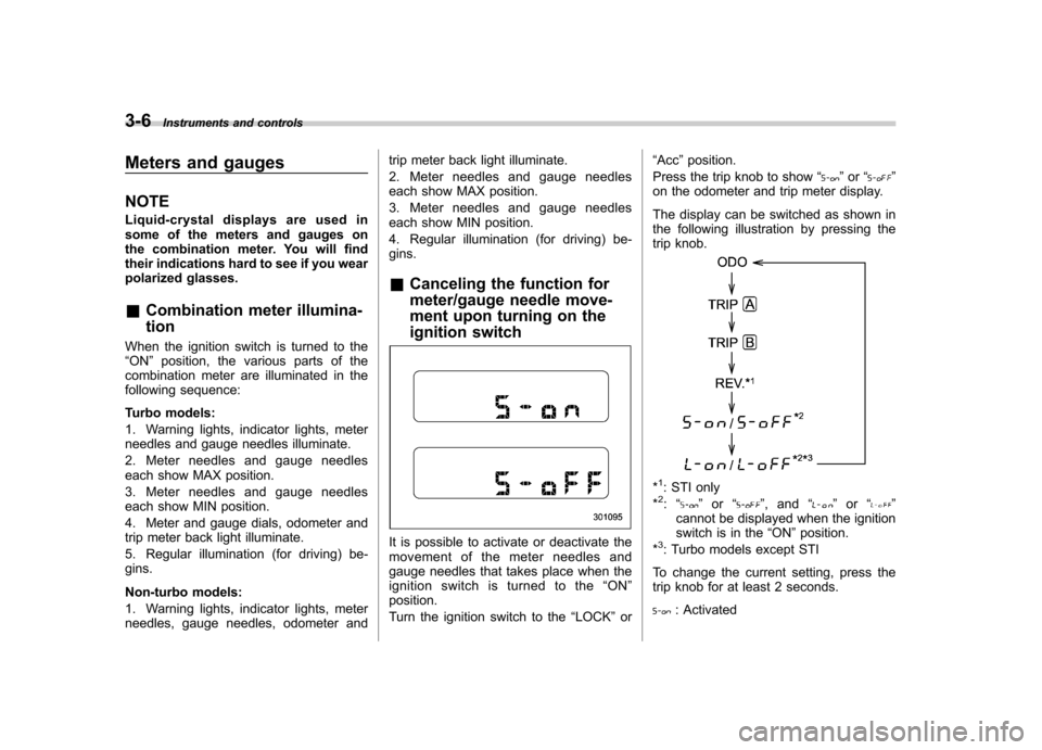
It is possible to activate or deactivate the
movement of the meter needles and
gauge needles that takes place when the
ignition switch is turned to the “ON ”
position.
Turn the ignition switch to the “LOCK ”or “
Acc ”position.
Press the trip knob to show “
”or “”
on the odometer and trip meter display.
The display can be switched as shown in
the following illustration by pressing the
trip knob.
*1: STI only
*2: “” or “”,and “”or “”
cannot be displayed when the ignition
switch is in the “ON ”position.
*
3: Turbo models except STI
To change the current setting, press the
trip knob for at least 2 seconds.
: Activated
Page 132 of 458

to OFF, OFF to ON, or the vehicle starts
moving before the setting procedure isfinished..Setting the speed is impossible
when the vehicle is moving.. The set engine speed may differ
from the engine speed shown by the
tachometer. Use the engine speed
shown by the tachometer as a roughguide.. If the setting operation is performed
with the engine switch turned off, the
REV indicator light turns off and the
setting operation is aborted when you
have stopped the setting operation for
approximately 10 seconds. . If the setting operation is performed
with the engine switch turned off, the
REV indicator light turns off and the
setting operation is aborted when you
open and close the driver ’s door.
& Deactivating the REV alarm system
To deactivate the REV indicator light and
buzzer functions of the REV alarm system,
set the thousands place of the alarm-level
engine speed to “–”. Warning and indicator lights
Several of the warning and indicator lights
illuminate momentarily and then turn off
when the ignition switch is initially turned
to the
“ON ”position. This permits check-
ing the operation of the bulbs.
Apply the parking brake and turn the
ignition switch to the “ON ”position. For
the system check, the following lights
illuminate and turn off after several sec-
onds or after the engine has started:
: Seatbelt warning light (The seatbelt warning light turns off
only when the driver fastens theseatbelt.)
: Front passenger ’s seatbelt warning
light
(The seatbelt warning light turns off
only when the front seat passenger
fastens the seatbelt.)
: SRS airbag system warning light
ON /
: Front passenger ’s frontal airbag
ON indicator light
/: Front passenger ’s frontal airbag
OFF indicator light
: CHECK ENGINE warning light/Mal- function indicator lamp
: Coolant temperature high warning light(non-turbo models)
: Charge warning light
: Oil pressure warning light
: AT OIL TEMP warning light (AT models)
: Rear differential oil temperature warn-ing light (STI)
: Low tire pressure warning light (U.S.- spec. models)
/: ABS warning light
/: Brake system warning light
: Low fuel warning light
: Hill start assist warning light (MT models –if equipped)/Hill start assist
OFF indicator light (STI)
: Door open warning light
: AWD warning light (AT models)
: Vehicle Dynamics Control operation
indicator light
: Vehicle Dynamics Control warning light/Vehicle Dynamics Control OFF
indicator light/Traction Control OFF
indicator light (STI) Instruments and controls
3-13
– CONTINUED –
Page 133 of 458
3-14Instruments and controls
: SPORT mode indicator light
(AT models)
: Cruise control indicator light
: Cruise control set indicator light
: Shift-up indicator light (STI)
: REV indicator light (STI)
:Driver ’s control center differential
indicator and warning lights (STI)
If any lights fail to illuminate, it indicates a
burned-out bulb or a malfunction of the
corresponding system.
Consult your authorized SUBARU dealer
for repair. & Seatbelt warning light
and chime
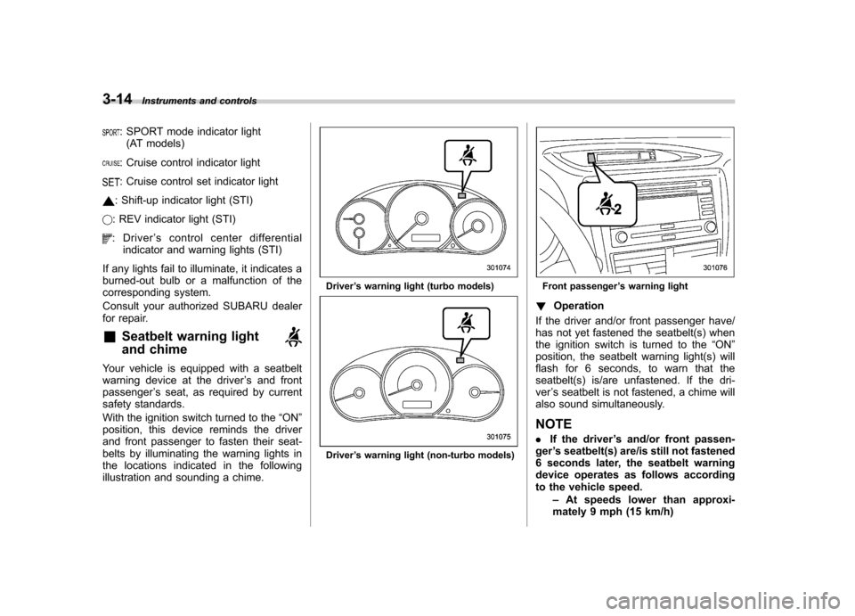
Your vehicle is equipped with a seatbelt
warning device at the driver ’s and front
passenger ’s seat, as required by current
safety standards.
With the ignition switch turned to the “ON ”
position, this device reminds the driver
and front passenger to fasten their seat-
belts by illuminating the warning lights in
the locations indicated in the following
illustration and sounding a chime.
Driver ’s warning light (turbo models)
Driver ’s warning light (non-turbo models)
Front passenger ’s warning light
! Operation
If the driver and/or front passenger have/
has not yet fastened the seatbelt(s) when
the ignition switch is turned to the “ON ”
position, the seatbelt warning light(s) will
flash for 6 seconds, to warn that the
seatbelt(s) is/are unfastened. If the dri-ver ’s seatbelt is not fastened, a chime will
also sound simultaneously. NOTE . If the driver ’s and/or front passen-
ger ’s seatbelt(s) are/is still not fastened
6 seconds later, the seatbelt warning
device operates as follows according
to the vehicle speed.
–At speeds lower than approxi-
mately 9 mph (15 km/h)
Page 141 of 458

3-22Instruments and controls
If the brake system warning light should
illuminate while driving (with the parking
brake fully released and with the ignition
switch positioned in “ON ”), it could be an
indication of leaking of brake fluid or worn
brake pads. If this occurs, immediately
stop the vehicle at the nearest safe place
and check the brake fluid level. If the fluid
level is below the “MIN ”mark in the
reservoir, do not drive the vehicle. Have
the vehicle towed to the nearest SUBARU
dealer for repair. ! Electronic Brake Force Distribution
(EBD) system warning
The brake system warning light also
illuminates if a malfunction occurs in the
EBD system. In that event, it illuminates
together with the ABS warning light.
The EBD system may be malfunctioning if
the brake system warning light and ABS
warning light illuminate simultaneously
during driving.
Even if the EBD system fails, the conven-
tional braking system will still function.
However, the rear wheels will be more
prone to locking when the brakes are
applied harder than usual and the vehi-cle ’s motion may therefore become some-
what harder to control.
If the brake system warning light and ABS
warning light illuminate simultaneously, take the following steps.
1. Stop the vehicle in the nearest safe,
flat place.
2. Shut down the engine, apply the
parking brake and then restart it.
3. Release the parking brake. If both
warning lights turn off, the EBD system
may be malfunctioning. Drive carefully to
the nearest SUBARU dealer and have the
system inspected.
4. If both warning lights illuminate again
and remain illuminated after the engine
has been restarted, shut down the engine
again, apply the parking brake, and check
the brake fluid level.
5. If the brake fluid level is not below the “
MIN ”mark, the EBD system may be
malfunctioning. Drive carefully to the
nearest SUBARU dealer and have the
system inspected.
6. If the brake fluid level is below the “ MIN ”mark, DO NOT drive the vehicle.
Instead, have the vehicle towed to the
nearest SUBARU dealer for repair.
& Low fuel warning light
The low fuel warning light illuminates
when the tank is nearly empty approxi-
mately 2.6 US gal (10.0 liters, or 2.2 Imp
gal). It only operates when the ignition
switch is in the “ON ”position. When this light illuminates, fill the fuel tank immedi-
ately.
NOTE
This light does not turn off unless the
tank is replenished up to an internal
fuel quantity of approximately 3.7 US
gal (14 liters, 3.1 Imp gal).
CAUTION
Promptly put fuel in the tank when-
ever the low fuel warning light
illuminates. Engine misfires as a
result of an empty tank could cause
damage to the engine.
& Hill start assist warning
light (MT models –if
equipped)/Hill start as-
sist OFF indicator light (STI)
! Hill start assist warning light
While the engine is rotating, if there are
any malfunctions in the Hill start assist
system, the light will illuminate.
WARNING
When the Hill start assist warning
Page 146 of 458
turn it again to the“ON ”position.
. If this indicator light and the CHECK
ENGINE warning light/malfunction in-
dicator lamp flash simultaneously dur-
ing driving, have the vehicle checked
by your nearest SUBARU dealer. & Cruise control set in-
dicator light
This light illuminates when vehicle speed
has been set. &Front fog light indicator
light (if equipped)
This indicator light illuminates while the
front fog lights are illuminated. & Headlight indicator
light (if equipped)
This indicator light illuminates when the
headlight switch is placed in the “”or
“” position. &
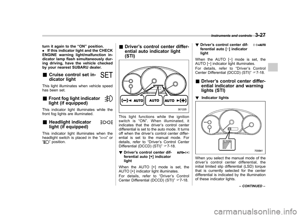
Driver ’s control center differ-
ential auto indicator light (STI)
This light functions while the ignition
switch is “ON ”. When illuminated, it
indicates that the driver ’s control center
differential is set to the auto mode. It turns
off when the driver ’s control center differ-
ential is set to the manual mode. For
details, refer to “Driver ’s Control Center
Differential (DCCD) (STI) ”F 7-18.
! Driver ’s control center dif-
ferential auto [+] indicatorlight
When the AUTO [+] mode is set, the
AUTO [+] indicator light illuminates.
For details, refer to “Driver ’sControl
Center Differential (DCCD) (STI) ”F 7-18. !
Driver ’s control center dif-
ferential auto [ �] indicator
light
When the AUTO [ �] mode is set, the
AUTO [ �] indicator light illuminates.
For details, refer to “Driver ’s Control
Center Differential (DCCD) (STI) ”F 7-18.
& Driver ’s control center differ-
ential indicator and warning
lights (STI)
! Indicator lights
When you select the manual mode of the driver ’s control center differential, the
initial limited slip differential (LSD) torque
that is currently selected for the center
differential is indicated by the illumination
of these indicator lights. Instruments and controls
3-27
– CONTINUED –
Page 147 of 458
3-28Instruments and controls
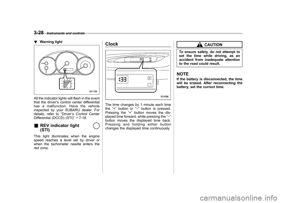
!Warning light
All the indicator lights will flash in the event
that the driver ’s control center differential
has a malfunction. Have the vehicle
inspected by your SUBARU dealer. For
details, refer to “Driver ’s Control Center
Differential (DCCD) (STI) ”F 7-18.
& REV indicator light (STI)
This light illuminates when the engine
speed reaches a level set by driver or
when the tachometer needle enters the
red zone. Clock
The time changes by 1 minute each time the
“+ ” button or “� ” button is pressed.
Pressing the “+ ” button moves the dis-
played time forward, while pressing the “� ”
button moves the displayed time back.
Pressing and holding either button
changes the displayed time continuously.
CAUTION
To ensure safety, do not attempt to
set the time while driving, as an
accident from inadequate attention
to the road could result.
NOTE
If the battery is disconnected, the time
will be erased. After reconnecting the
battery, set the correct time.
Page 152 of 458
&Daytime running light system
WARNING
The brightness of the illumination of
the high beam headlights is reduced
by the daytime running light system.
The light switch must always be
turned to the “
”position when it
is dark outside.
The high beam headlights will automati-
cally illuminate at reduced brightness
when the engine has started, under the
following conditions: . The select lever is in a position other
than the “P ”position (AT models).
. The parking brake is fully released.
. The light switch is in the “OFF ”or “
”
position.
NOTE
When the light switch is in the “
”
position, the front side marker lights,
tail lights and license plate lights areilluminated. Turn signal lever
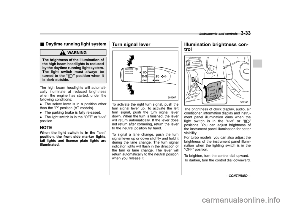
To activate the right turn signal, push the
turn signal lever up. To activate the left
turn signal, push the turn signal lever
down. When the turn is finished, the lever
will return automatically. If the lever does
not return after cornering, return the lever
to the neutral position by hand.
To signal a lane change, push the turn
signal lever up or down slightly and hold it
during the lane change. The turn signal
indicator lights will flash in the direction of
the turn or lane change. The lever will
return automatically to the neutral position
when you release it.Illumination brightness con- trol
The brightness of clock display, audio, air
conditioner, information display and instru-
ment panel illumination dims when the
light switch is in the
“
”or “”
positions. You can adjust brightness of
the instrument panel illumination for better
visibility.
For turbo models, you can also adjust the
brightness of the instrument panel illumi-
nation when the lighting switch is in the“ OFF ”position.
To brighten, turn the control dial upward.
To darken, turn the control dial downward. Instruments and controls
3-33
– CONTINUED –
Page 155 of 458

3-36Instruments and controls
Front fog light switch (if equipped)
The front fog lights operate only when the
light switch is in the “”position.
However, the front fog lights turn off when
the headlights are switched to high beam.
To turn on the front fog lights, turn the front
fog light switch on the turn signal lever
upward to the “
”position. To turn off the
front fog lights, turn the switch back down
to the “OFF ”position.
Turbo models
Non-turbo models
The indicator light on the combination
meter will illuminate when the front fog
lights are illuminated. Wiper and washer
WARNING
In freezing weather, do not use the
windshield washer until the wind-
shield is sufficiently warmed by the
defroster.
Otherwise the washer fluid can
freeze on the windshield, blocking
your view.
CAUTION
. Do not operate the washer con-
tinuously for more than 10 sec-
onds, or when the washer fluid
tank is empty. This may cause
overheating of the washer motor.
Check the washer fluid level
frequently, such as at fuel stops.
. Do not operate the wipers when
the windshield or rear window is
dry. This may scratch the glass,
damage the wiper blades and
cause the wiper motor to burn
out. Before operating the wiper
on a dry windshield or rear
window, always use the wind-
shield washer.