2011 SUBARU IMPREZA WRX odometer
[x] Cancel search: odometerPage 125 of 458

3-6Instruments and controls
Meters and gauges NOTE
Liquid-crystal displays are used in
some of the meters and gauges on
the combination meter. You will find
their indications hard to see if you wear
polarized glasses. &Combination meter illumina- tion
When the ignition switch is turned to the “ ON ”position, the various parts of the
combination meter are illuminated in the
following sequence:
Turbo models:
1. Warning lights, indicator lights, meter
needles and gauge needles illuminate.
2. Meter needles and gauge needles
each show MAX position.
3. Meter needles and gauge needles
each show MIN position.
4. Meter and gauge dials, odometer and
trip meter back light illuminate.
5. Regular illumination (for driving) be- gins.
Non-turbo models:
1. Warning lights, indicator lights, meter
needles, gauge needles, odometer and trip meter back light illuminate.
2. Meter needles and gauge needles
each show MAX position.
3. Meter needles and gauge needles
each show MIN position.
4. Regular illumination (for driving) be- gins.
& Canceling the function for
meter/gauge needle move-
ment upon turning on the
ignition switch
It is possible to activate or deactivate the
movement of the meter needles and
gauge needles that takes place when the
ignition switch is turned to the “ON ”
position.
Turn the ignition switch to the “LOCK ”or “
Acc ”position.
Press the trip knob to show “
”or “”
on the odometer and trip meter display.
The display can be switched as shown in
the following illustration by pressing the
trip knob.
*1: STI only
*2: “” or “”,and “”or “”
cannot be displayed when the ignition
switch is in the “ON ”position.
*
3: Turbo models except STI
To change the current setting, press the
trip knob for at least 2 seconds.
: Activated
Page 126 of 458

: Deactivated
NOTE . Your vehicle ’s initial movement
setting of the meter/gauge needles
has been set for activation “
”at the
time of shipment from the factory. . It is not possible to cancel the initial
movement setting of the meter/gauge
needles when the ignition switch is inthe “ON ”position. Cancel the setting
whentheignitionswitchisinthe“ LOCK ”or “Acc ”position.
& Meter/Gauge needle illumi-
nation setting (turbo models
except STI)
When the setting is activated or deacti-
vated, the meter needles and gauge
needles illuminate and turn off as follows. Activated:
When the driver ’s door is opened while
theignitionswitchisinthe “LOCK ”
position, the needles illuminate and turn
off after approximately 20 seconds. The
illumination of the needles gradually turns
off after the ignition switch is turned fromthe “ON ”position to the “LOCK ”position.
Deactivated:
The needles do not illuminate when thedriver ’s door is opened while the ignition switch is in the
“LOCK ”position. The
illumination of the needles turns off im-
mediately after the ignition switch is turned
from the “ON ”position to the “LOCK ”
position.
NOTE . Even during the illumination after
the driver ’s door is opened, if the
ignition switch is turned to the “ON ”
position, the combination meter will
illuminate as usual.. If the doors are locked by the remote
keyless entry system during the illumi-
nation after the driver ’s door is opened,
the illumination will be turned off.. Even while the illumination gradu-
ally turns off after the ignition switch is
turned to the “LOCK ”position, if the
ignition switch is turned to the “ON ”
position, the combination meter illumi-
nate as usual.
To change the setting:
1. Turn the ignition switch to the “LOCK ”
or “Acc ”position.
2. Press the trip knob to show “”or
“” on the odometer and trip meter
display. The display can be switched as
shown in the following illustration by
pressing the trip knob.
*: “”or “”, and “”or “”cannot
Instruments and controls
3-7
– CONTINUED –
Page 127 of 458
3-8Instruments and controls
be displayed when the ignition switch is
in the “ON ”position.
3. To change the current setting, press
the trip knob for at least 2 seconds.
: Activated
: Deactivated
NOTE
The initial illumination setting of the
meter/gauge needles of your vehicle
has been set for activation “
”at the
time of shipment from the factory.
& Speedometer
The speedometer shows the vehicle speed. &
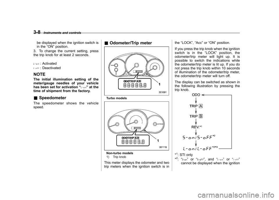
Odometer/Trip meter
Turbo models
Non-turbo models
1) Trip knob
This meter displays the odometer and two
trip meters when the ignition switch is in the
“LOCK ”, “Acc ”or “ON ”position.
If you press the trip knob when the ignition
switch is in the “LOCK ”position, the
odometer/trip meter will light up. It is
possible to switch the indications while
the odometer/trip meter is lit up. If you do
not press the trip knob within 10 seconds
of illumination of the odometer/trip meter,
the odometer/trip meter will turn off.
The display can be switched as shown in
the following illustration by pressing the
trip knob.*1: STI only
*2: “” or “”,and “”or “”
cannot be displayed when the ignition
Page 128 of 458

switch is in the“ON ”position.
*3: Turbo models except STI
! Odometer
The odometer shows the total distance
that the vehicle has been driven. !
Double trip meter
The trip meter shows the distance that the
vehicle has been driven since you last set
it to zero.
To set the trip meter to zero, select the A
trip or B trip meter by pushing the knob
and keep the knob pushed for more than 2seconds.
CAUTION
To ensure safety, do not attempt to
change the function of the indicator
during driving, as an accident couldresult.
NOTE
If the connection between the combina- tion meter and battery is broken for any
reason such as vehicle maintenance or
fuse replacement, the data recorded on
the trip meter will be lost. &
Tachometer
The tachometer shows the engine speed
in thousands of revolutions per minute.
CAUTION
Do not operate the engine with the
pointer of the tachometer in the red
zone. This may cause severe da-
mage to the engine.
NOTE
For non-turbo models, to protect the
engine while the select lever is in the“ P ” or “N ” position (for AT models) or
the shift lever is in the neutral position
(for MT models), the engine is con-
trolled so that the engine speed may
not become too high even if the accel-
erator pedal is depressed hard. Instruments and controls
3-9
– CONTINUED –
Page 130 of 458
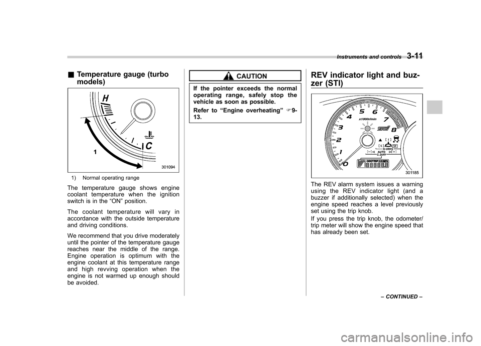
&Temperature gauge (turbo models)
1) Normal operating range
The temperature gauge shows engine
coolant temperature when the ignition
switch is in the “ON ”position.
The coolant temperature will vary in
accordance with the outside temperature
and driving conditions.
We recommend that you drive moderately
until the pointer of the temperature gauge
reaches near the middle of the range.
Engine operation is optimum with the
engine coolant at this temperature range
and high revving operation when the
engine is not warmed up enough should
be avoided.
CAUTION
If the pointer exceeds the normal
operating range, safely stop the
vehicle as soon as possible.
Refer to “Engine overheating ”F9-
13. REV indicator light and buz-
zer (STI)
The REV alarm system issues a warning
using the REV indicator light (and a
buzzer if additionally selected) when the
engine speed reaches a level previously
set using the trip knob.
If you press the trip knob, the odometer/
trip meter will show the engine speed that
has already been set.Instruments and controls
3-11
– CONTINUED –
Page 148 of 458
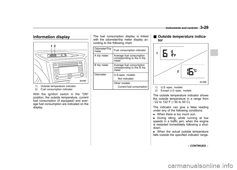
Information display
1) Outside temperature indicator
2) Fuel consumption indicator
With the ignition switch in the “ON ”
position, the outside temperature, current
fuel consumption (if equipped) and aver-
age fuel consumption are indicated on the
display. The fuel consumption display is linked
with the odometer/trip meter display ac-
cording to the following chart.
Odometer/Trip meter Fuel consumption indicator
A trip meter Average fuel consumption corresponding to the A trip meter
B trip meter Average fuel consumption corresponding to the B trip meter
Odometer U.S-spec. models:
Not indicated
Other models: Current fuel consumption &
Outside temperature indica- tor1) U.S.-spec. models
2) Except U.S.-spec. models
The outside temperature indicator shows
the outside temperature in a range from� 22 to 122 8F( �30 to 50 8C).
The indicator can give a false reading
under any of the following conditions: . When there is too much sun.
. During idling; while running at low
speeds in a traffic jam; when the engine
is restarted immediately following a shut- down. . When the actual outside temperature
falls outside the specified indicator range. Instruments and controls
3-29
– CONTINUED –
Page 321 of 458
8-10Driving tips
roads. This may cause loss of
vehicle control.
CAUTION
Avoid prolonged continuous driving
in snowstorms. Snow will enter the
engine ’s intake system and may
hinder the airflow, which could re-
sult in engine shutdown or evenbreakdown.
! Wiper operation when snowing
Before driving in cold weather, make sure
the wiper blades are not frozen to the
windshield or rear window.
If the front wiper blades are frozen to the
windshield, use the defroster with the
airflow control dial in the “
”position
and the temperature control dial set for
maximum warmth until the wiper blades
are completely thawed out. For details,
refer to the following section. . For the manual climate control system,
refer to “Defrosting or defogging the
windshield ”F 4-5.
. For the automatic climate control sys-
tem, refer to “Control panel ”F 4-8.
If your vehicle is equipped with a wind-
shield wiper deicer, it is helpful to thaw the windshield wiper blades. Refer to
“Defog-
ger and deicer ”F 3-48.
If the rear wiper blade is frozen to the rear
window, use the rear window defogger.
Refer to “Defogger and deicer ”F 3-48.
When driving in snow, if frozen snow starts
to stick on the surface of the windshield
despite wiper operation, use the defroster
with the airflow control dial in “
”and the
temperature control dial set for maximum
warmth. After the windshield gets warmed
enough to melt the frozen snow on it,
wash it away using the windshield washer.
Refer to “Washer ”F 3-39.
Snow stuck on the wiper arm prevents the
wiper from working effectively. If snow is
stuck on the wiper arm, pull off the road to
a safe place, then remove it. If you stop
the vehicle at road side, use the hazard
warning flasher to alert other drivers.
We recommend use of non-freezing type
wiper blades (winter blades) during the
seasons you could have snow and freez-
ing temperatures. Blades of this type give
superior wiping performance in snowy
conditions. Be sure to use blades that
are suitable for your vehicle.
CAUTION
During high-speed driving, non- freezing type wiper blades may not
perform as well as standard wiper
blades. If this happens, reduce the
vehicle speed.
NOTE
When the season requiring non-freez-
ing type wiper blades is over, replace
them with standard wiper blades. & Corrosion protection
Refer to “Corrosion protection ”F 10-4.
& Snow tires
WARNING
. When replacing original tires with
winter (snow) tires, make sure
you use only the same size,
construction and load range as
the original tires listed on the tire
placard. Using other sizes and
construction may affect speed-
ometer/odometer calibration and
clearance between the body and
tires. It also may be dangerous
and lead to loss of vehicle con-trol.
. You must install four winter tires
Page 322 of 458
that are of the same size, con-
struction, brand, and load range.
Mixing other sizes or construc-
tions may result in severe me-
chanical damage to the drive
train of your vehicle and may
affect ride, handling, braking and
speedometer/odometer calibra-
tion. It also may be dangerous
and lead to loss of vehicle con-trol.
. Do not use a combination of
radial, belted bias or bias tires
since it may cause dangerous
handling characteristics and lead
to an accident.
! Turbo models
Your vehicle is equipped with “summer
tires ”as original equipment, which are
inadequate for driving on slippery roads
such as on snow-covered or icy roads.
Compared with winter and all-season
tires, summer tires give significantly less
grip on snowy and icy road surfaces.
Therefore, use of winter tires is strongly
recommended when driving with such
road conditions.
When you choose to install winter tires on
your vehicle, be sure to use the correct tire
size and type. You must install four winter tires that are of the same size, construc-
tion, brand and load range and you should
never mix radial, belted bias or bias tires
since this may result in dangerous hand-
ling characteristics. When you choose a
tire, make sure that there is enough
clearance between the tire and vehicle
body.
Remember to drive with care at all times
regardless of the type of tires on yourvehicle. !
Non-turbo models
Your vehicle is equipped with “all season
tires ”as original equipment, which are
designed to provide an adequate measure
of traction, handling and braking perfor-
mance in year-round driving. In winter, it
may be possible to enhance performance
through use of tires designed specifically
for winter driving conditions.
When you choose to install winter tires on
your vehicle, be sure to use the correct tire
size and type. You must install four winter
tires that are of the same size, construc-
tion, brand and load range and you should
never mix radial, belted bias or bias tires
since this may result in dangerous hand-
ling characteristics. When you choose a
tire, make sure that there is enough
clearance between the tire and vehicle
body. Remember to drive with care at all times
regardless of the type of tires on yourvehicle.
& Tire chains
CAUTION
Tire chains cannot be used on your
Impreza, WRX and STI because of
the lack of clearance between the
tires and vehicle body.
& Rocking the vehicle
If you must rock the vehicle to free it from
snow, sand, or mud, depress the accel-
erator pedal slightly and move the shift
lever/select lever back and forth between“ 1 ”/“ D ”and “R ”repeatedly. Do not race the
engine. For the best possible traction,
avoid spinning the wheels when trying to
free the vehicle.
When the road surface is extremely
slippery, you can obtain better traction by
starting the vehicle with the transmission
in 2nd than 1st (both for MT and AT).
If your vehicle is an AT model, for
information about holding the transmission
in the 2nd position, refer to “Selection of
manual mode ”F 7-26. Driving tips
8-11