2011 SUBARU IMPREZA WRX horn
[x] Cancel search: hornPage 170 of 458

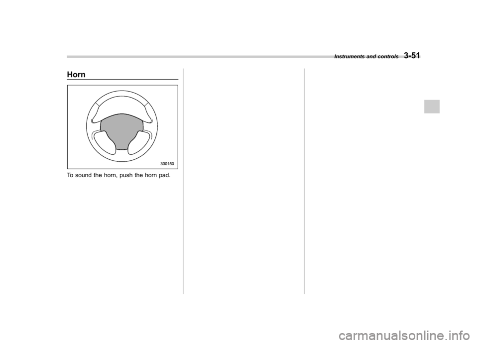
Horn
To sound the horn, push the horn pad.Instruments and controls
3-51
Page 274 of 458

Remote engine start system
(dealer option)
WARNING
. Do not start the engine using the
remote start system in an en-
closed environment (e.g., in a
closed garage). Prolonged opera-
tion of a motor vehicle in an
enclosed environment can cause
a harmful build-up of Carbon
Monoxide. Carbon Monoxide is
harmful to your health. Exposure
to high levels of Carbon Monox-
ide can cause headaches, dizzi-
ness or in extreme cases uncon-
sciousness and/or death.
. Before performing any servicing
of the vehicle, temporarily place
the remote engine start system in
service mode to prevent the
system from unexpectedly start-
ing the engine.
& Starting your vehicle
The remote engine start system is acti-
vated by pressing the “
”button twice
within 3 seconds on your remote engine
start transmitter. The system will check
certain pre-conditions before starting, and
if all safety parameters are correct, the
engine will start within 5 seconds. While
the vehicle is operating via remote engine
start, the vehicle ’s power window features
will be disabled. Also, the system has a
timer and will shut down after 15 minutes if
you do not operate the vehicle. Press and
hold the “
”button for 2 seconds again to
turn the vehicle off. If the vehicle ’s starter
cranks but does not start or starts and
stalls, the remote engine start system will
power off then attempt to start the vehicle an additional four times. If the vehicle fails
to start after the additional attempts, the
remote engine start system will abort and
return to a non-activated state.
& Remote start safety features
For safety and security reasons, the
system will fail to start and beep the horn
twice or shut down the engine during
remote start operation if any of the
following conditions occur. . The brake pedal is depressed before
the vehicle ignition switch is turned “on ”.
. The key was already in the ignition
switch.. The engine hood is opened.
. The vehicle ’s engine idle speed has
reached a level over 3,000 rpm.. The alarm is triggered by opening a
door or the rear gate.
NOTE . The security indicator light on the
combination meter will stop flashing
while under remote engine start opera-
tion, but the vehicle is still protected.. If the vehicle is entered during
remote engine star t operation, the
system will not record entry in the
alarm history. Starting and operating
7-11
– CONTINUED –
Page 275 of 458

7-12Starting and operating
& Entering the vehicle while it
is running via remote start
1. Unlock the vehicle doors using the
remote keyless entry system. If the vehi-cle ’s doors are unlocked manually using
the key, the vehicle ’s alarm system will
trigger and the remote engine start system
will turn off. Inserting the key into the
ignition switch and turning it to the “ON ”
position or pressing the unlock button “
”
on the remote keyless entry transmitter
will disarm the alarm system. Refer to“ Alarm system ”F 2-16.
2. Enter the vehicle. Do not depress the
brake pedal.
3. Insert the key into the ignition switch
and turn to the “ON ”position. If the ignition
switch is accidentally turned to the“ START ”position, the system ’s “starter
anti-grind ”feature will prevent the starter
from re-cranking.
4. Depress the brake pedal. The remote
starter disengages, the vehicle ’s power
window features are re-enabled and the
vehicle will operate normally.
& Entering the vehicle follow-
ing remote engine start shut-down
An alarm trigger may occur if the vehicle is
opened by the remote keyless entry transmitter within a few seconds immedi-
ately following remote engine start shut-down.
& Pre-heating or pre-cooling
the interior of the vehicle
Before exiting the vehicle, set the tem-
perature controls to the desired setting
and operation. After the system starts the
vehicle, the heater or air-conditioning will
activate and heat or cool the interior to
your setting. & Service mode
In service mode, the remote start function
is temporarily disabled to prevent the
system from unexpectedly starting the
engine while being serviced. ! To engage the service mode
Turn the ignition switch to the “ON ”
position, depress and hold the brake
pedal, then press and release the “
”
button on the remote engine start trans-
mitter three times. The system will pause
for 1 second and then flash the turn signal
lights and honk the horn three times
indicating that the system is in service
mode. When attempting to activate the
remote start system while in service
mode, the turn signal lights will flash and
the horn will honk two times and will not start. !
To disengage the service mode
Turntheignitionswitchtothe “ON ”
position, depress and hold the brake
pedal, then press and release the “
”
button on the remote engine start trans-
mitter three times. The system will pause
for 1 second and flash the turn signal
lights once indicating that the system has
exited service mode.
NOTE
When taking your vehicle in for service,
it is recommended that you inform the
service personnel that your vehicle is
equipped with a remote engine startsystem. & Remote engine start trans-
mitter programming and pro-
grammable feature option
New transmitters can be programmed to
the remote engine start system in the
event that remote engine start transmitters
are lost, stolen or damaged. The remote
engine start system also has one pro-
grammable feature that can be adjusted
for user preference.
The remote engine start system can be
programmed to either make an audible
horn chirp upon remote start activation or
Page 276 of 458

not. Remote engine start transmitter pro-
gramming and feature programming can
be adjusted using the following procedure.
1. Open the driver’s door (the driver ’s
door must remain opened throughout the
entire process).
2. Insert the key into the vehicle ’s ignition
switch and turn to the “ON ”position.
3. Locate the small black programming
button behind the fuse box cover, on the
driver ’s side left under the dashboard
panel.
4. Press and hold the black programming
button for 10 to 15 seconds. The horn will
honk and the turn signal lights will flash
three times to indicate that the system has
entered programming mode. At this point
you can proceed to either step 5 or step 6.
5. To program a remote engine start
transmitter: press and release the “
”
button on each transmitter. The horn will
honk and the turn signal lights will flash
one time to indicate a successful trans-
mitter learn each time the “
”button is
pressed. You can program up to eight transmitters.
6. To toggle the Horn Confirmation chirps
ON/OFF: depress and release the brake
pedal to toggle the feature. The horn will
chirp and the turn signal lights will flash
one time to indicate Confirmation Horn
Chirps are “OFF ”. The horn will honk and the turn signal lights will flash 2 times to
indicate Confirmation Horn Chirps are“
ON ”. Depressing the brake pedal repeat-
edly will toggle the feature ON or OFF
each time.
7. To exit the remote engine start trans-
mitter and feature programming mode,
turn the ignition switch to the “LOCK ”
position, remove the key from the ignition
switch and test operation of the remote
engine start transmitter(s) and horn con-
firmation feature.
& System maintenance
! Changing the batteries
CAUTION
. Do not let dust, oil or water get on
or in the remote engine start
transmitter when replacing the
battery.
. Be careful not to damage the
printed circuit board in the re-
mote engine start transmitter
when replacing the battery.
. Be careful not to allow children to
touch the battery and any re-
moved parts; children could
swallow them.
. There is a danger of explosion if an incorrect replacement battery
is used. Replace only with the
same or equivalent type of bat-
tery.
. Batteries should not be exposed
to excessive heat such as sun-
shine, fire or the like.
The two 3-volt lithium batteries (modelCR-1220 ) supplied in your remote engine
start transmitter should last approximately
3 years, depending on usage. When the
batteries begin to weaken, you will notice
a decrease in range (distance from the
vehicle that your remote engine start
system operates). Follow the instructions
below to change the remote engine start
transmitter batteries.
Starting and operating 7-13
– CONTINUED –
Page 423 of 458

12-14Specifications
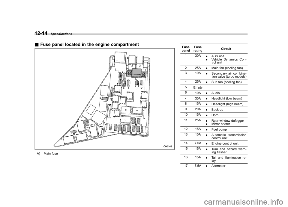
&Fuse panel located in the engine compartment
A) Main fuse Fuse
panel Fuse
rating Circuit
1 30A .ABS unit
. Vehicle Dynamics Con-
trol unit
2 25A .Main fan (cooling fan)
3 10A .Secondary air combina-
tion valve (turbo models)
4 25A .Sub fan (cooling fan)
5 Empty
6 10A .Audio
7 30A .Headlight (low beam)
8 15A .Headlight (high beam)
9 20A .Back-up
10 15A .Horn
11 25A .Rear window defogger
. Mirror heater
12 15A .Fuel pump
13 10A .Automatic transmission
control unit
14 7.5A .Engine control unit
15 15A .Turn and hazard warn-
ing flasher
16 15A .Tail and illumination re-
lay
17 7.5A .Alternator
Page 451 of 458

14-6Index
Heater operation (manual climate control system) .. .......... 4-5
High beam indicator light ............................................ 3-26
High mount stop light ................................................. 11-55
High/low beam change (dimmer) .................................. 3-32
Hill start assist (MT models) ............................... 7-42, 11-29
OFF indicator light .................................................. 3-23
To activate/deactivate ............................................. 7-42
Warning light ................................................. 3-22, 3-22
HomeLink
®................................................................ 3-41
Hook Cargo tie-down ...................................................... 6-13
Shopping bag ........................................................ 6-11
Towing and tie-down ............................................... 9-14
Horn ......................................................................... 3-51
Hose and connections ............................................... 11-14
I
Ignition switch .............................................................. 3-3
Light ....................................................................... 3-5
Illumination brightness control ...................................... 3-33
Immobilizer. ................................................................. 2-2
Indicator light (security indicator light) ....................... 3-25
Indicator light Coolant temperature low ......................................... 3-17
Cruise control ........................................................ 3-26
Cruise control set ................................................... 3-27
Front fog light ........................................................ 3-27
Headlight .............................................................. 3-27
High beam ............................................................ 3-26
Hill start assist OFF ................................................ 3-23
Immobilizer. ........................................................... 3-25 REV.
..................................................................... 3-28
Security ................................................................. 3-25
Select lever/Gear position ........................................ 3-26
Shift-up ................................................................. 3-26
SI-DRIVE .............................................................. 3-26
SPORT mode ........................................................ 3-25
Traction control OFF ............................................... 3-23
Turn signal ............................................................ 3-26
Vehicle Dynamics Control OFF ................................. 3-23
Vehicle Dynamics Control operation .. ........................ 3-23
Information display ...................................................... 3-29
Inside mirror .............................................................. 3-40
Interior lights ............................................................... 6-2
Internal trunk lid release handle .................................... 2-25
iPod
®operations ........................................................ 5-37
J
Jack and jack handle ................................................... 9-5
Jack-up point .............................................................. 9-6
Jump starting ............................................................. 9-11
K
Key............................................................................ 2-2 Number .................................................................. 2-2
Reminder chime ...................................................... 3-5
Replacement. .......................................................... 2-3
L
Leather seat materials ................................................. 10-5
License plate light ..................................................... 11-53