2011 SUBARU IMPREZA WRX fuse
[x] Cancel search: fusePage 273 of 458

7-10Starting and operating
position and check the operation of the
warning and indicator lights. Refer to“Warning and indicator lights ”F 3-13.
5. Turn the ignition switch to the “START ”
position without depressing the accelera-
tor pedal. Release the key immediately
after the engine has started.
If the engine does not start, try the following.
(1) Turn the ignition switch to the“OFF ”position and wait for at least
10 seconds. After checking that the
parking brake is firmly set, turn the
ignition switch to the “START ”position
while depressing the accelerator pedal
slightly (approximately a quarter of the
full stroke). Release the accelerator
pedal as soon as the engine starts.
(2) If this fails to start the engine, turn
the ignition switch back to the “OFF ”
position and wait for at least 10
seconds. Then fully depress the accel-
erator pedal and turn the ignition
switch to the “START ”position. If the
engine starts, quickly release the
accelerator pedal.
(3) If this fails to start the engine, turn
the ignition switch again to the “OFF ”
position. After waiting for 10 seconds
or longer, turn the ignition switch to the“ START ”position without depressing
the accelerator pedal. (4) If the engine still refuses to start,
contact your nearest SUBARU dealer
for assistance.
6. Confirm that all warning and indicator
lights have turned off after the engine has
started. The fuel injection system auto-
matically lowers the idle speed as the
engine warms up.
While the engine is warming up, make
sure that the select lever is at the “P ” or
“ N ”position and that the parking brake is
applied.
CAUTION
If you restart the engine while the
vehicle is moving, shift the select
lever into the “N ” position. Do not
attempt to place the select lever of a
moving vehicle into the “P ” posi-
tion. Stopping the engine
The ignition switch should be turned off
only when the vehicle is stopped and the
engine is idling.
WARNING
Do not stop the engine when the
vehicle is moving. This will cause
loss of power to the power steering
and the brake booster, making steer-
ing and braking more difficult. It
could also result in accidental acti-
vation of the “LOCK ”position on the
ignition switch, causing the steering
wheel to lock.
Page 276 of 458

not. Remote engine start transmitter pro-
gramming and feature programming can
be adjusted using the following procedure.
1. Open the driver’s door (the driver ’s
door must remain opened throughout the
entire process).
2. Insert the key into the vehicle ’s ignition
switch and turn to the “ON ”position.
3. Locate the small black programming
button behind the fuse box cover, on the
driver ’s side left under the dashboard
panel.
4. Press and hold the black programming
button for 10 to 15 seconds. The horn will
honk and the turn signal lights will flash
three times to indicate that the system has
entered programming mode. At this point
you can proceed to either step 5 or step 6.
5. To program a remote engine start
transmitter: press and release the “
”
button on each transmitter. The horn will
honk and the turn signal lights will flash
one time to indicate a successful trans-
mitter learn each time the “
”button is
pressed. You can program up to eight transmitters.
6. To toggle the Horn Confirmation chirps
ON/OFF: depress and release the brake
pedal to toggle the feature. The horn will
chirp and the turn signal lights will flash
one time to indicate Confirmation Horn
Chirps are “OFF ”. The horn will honk and the turn signal lights will flash 2 times to
indicate Confirmation Horn Chirps are“
ON ”. Depressing the brake pedal repeat-
edly will toggle the feature ON or OFF
each time.
7. To exit the remote engine start trans-
mitter and feature programming mode,
turn the ignition switch to the “LOCK ”
position, remove the key from the ignition
switch and test operation of the remote
engine start transmitter(s) and horn con-
firmation feature.
& System maintenance
! Changing the batteries
CAUTION
. Do not let dust, oil or water get on
or in the remote engine start
transmitter when replacing the
battery.
. Be careful not to damage the
printed circuit board in the re-
mote engine start transmitter
when replacing the battery.
. Be careful not to allow children to
touch the battery and any re-
moved parts; children could
swallow them.
. There is a danger of explosion if an incorrect replacement battery
is used. Replace only with the
same or equivalent type of bat-
tery.
. Batteries should not be exposed
to excessive heat such as sun-
shine, fire or the like.
The two 3-volt lithium batteries (modelCR-1220 ) supplied in your remote engine
start transmitter should last approximately
3 years, depending on usage. When the
batteries begin to weaken, you will notice
a decrease in range (distance from the
vehicle that your remote engine start
system operates). Follow the instructions
below to change the remote engine start
transmitter batteries.
Starting and operating 7-13
– CONTINUED –
Page 330 of 458

possible because the spare tire is de-
signed only for temporary use.
Check the inflation pressure of the tem-
porary spare tire periodically to keep the
tire ready for use. The correct pressure is
60 psi (420 kPa, 4.2 kg/cm
2).
When using the temporary spare tire, note
the following. . Do not exceed 50 mph (80 km/h).
. Do not put a tire chain on the temporary
spare tire. Because of the smaller tire size,
a tire chain will not fit properly. . Do not use two or more temporary
spare tires at the same time.. Do not drive over obstacles. This tire
has a smaller diameter, so road clearance
is reduced.
1) Tread wear indicator bar
2) Indicator location mark
. When the wear indicator appears on
the tread, replace the tire. . The temporary spare tire must be used
only on a rear wheel. If a front wheel tire
gets punctured, replace the wheel with a
rear wheel and install the temporary spare
tire in place of the removed rear wheel. & Precautions for AWD models
with automatic transmission
Your vehicle is equipped with the AWD
(All-Wheel Drive) system. In addition, if
your vehicle is an AT model, before driving
your vehicle with the temporary spare tire,
deactivate the AWD capability of the
vehicle as follows. 1. Turn the ignition switch to the
“LOCK ”
position.
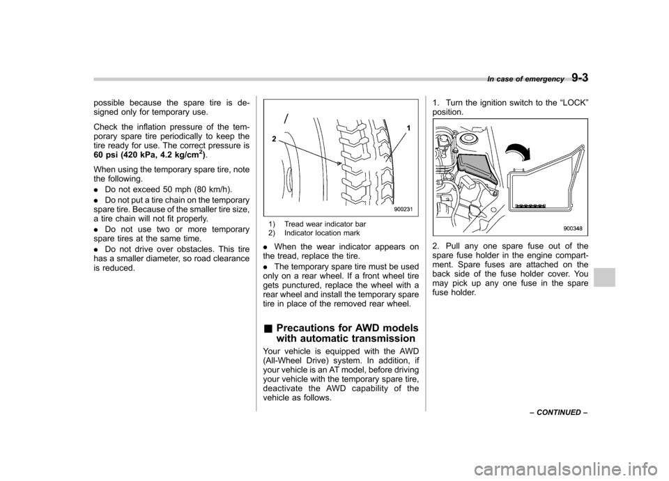
2. Pull any one spare fuse out of the
spare fuse holder in the engine compart-
ment. Spare fuses are attached on the
back side of the fuse holder cover. You
may pick up any one fuse in the spare
fuse holder. In case of emergency
9-3
– CONTINUED –
Page 331 of 458

9-4In case of emergency
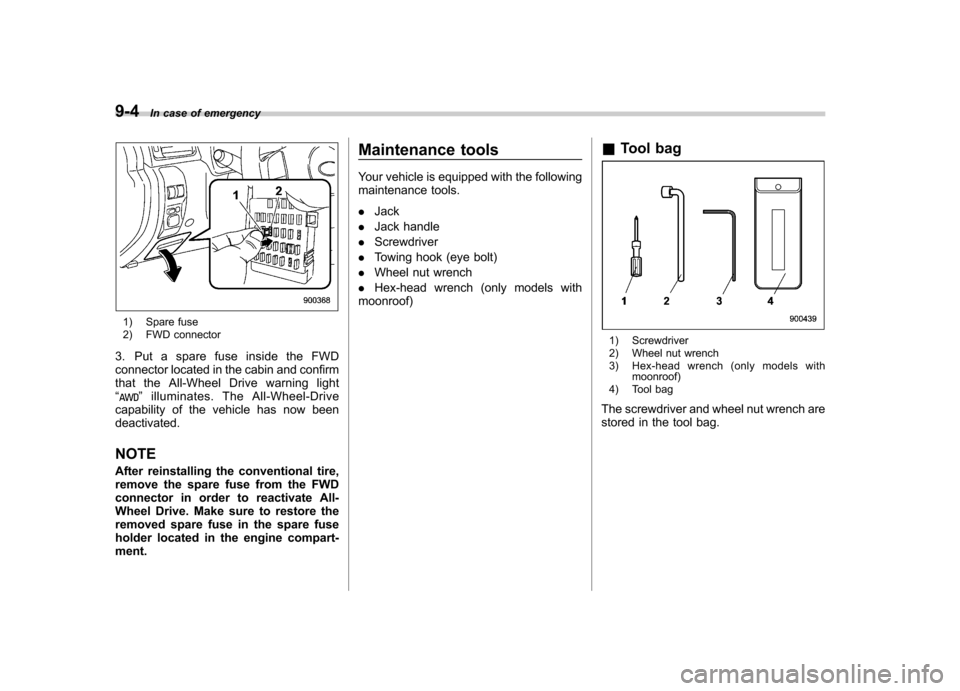
1) Spare fuse
2) FWD connector
3. Put a spare fuse inside the FWD
connector located in the cabin and confirm
that the All-Wheel Drive warning light“
” illuminates. The All-Wheel-Drive
capability of the vehicle has now been deactivated. NOTE
After reinstalling the conventional tire,
remove the spare fuse from the FWD
connector in order to reactivate All-
Wheel Drive. Make sure to restore the
removed spare fuse in the spare fuse
holder located in the engine compart-ment. Maintenance tools
Your vehicle is equipped with the following
maintenance tools. .
Jack
. Jack handle
. Screwdriver
. Towing hook (eye bolt)
. Wheel nut wrench
. Hex-head wrench (only models with
moonroof) &
Tool bag
1) Screwdriver
2) Wheel nut wrench
3) Hex-head wrench (only models with
moonroof)
4) Tool bag
The screwdriver and wheel nut wrench are
stored in the tool bag.
Page 355 of 458

Maintenance and serviceTires and wheels .............................................. 11-31
Types of tires ................................................... 11-31
Tire pressure monitoring system (TPMS) (if equipped) ................................................... 11-31
Tire inspection ................................................. 11-33
Tire pressures and wear ................................... 11-33
Wheel balance .................................................. 11-35
Wear indicators ................................................ 11-35
Tire rotation direction mark .............................. 11-36
Tire rotation ..................................................... 11-36
Tire replacement .............................................. 11-37
Wheel replacement ........................................... 11-37
Aluminum wheels ............................................. 11-38
Windshield washer fluid .................................. 11-38
Replacement of wiper blades .......................... 11-39
Windshield wiper blade assembly ..................... 11-40
Windshield wiper blade rubber (type A and type B) ........................................................... 11-41
Rear window wiper blade assembly .................. 11-42
Rear window wiper blade rubber ....................... 11-42Battery
.............................................................. 11-44
Fuses ................................................................ 11-45
Main fuse .......................................................... 11-46
Installation of accessories .............................. 11-46
Replacing bulbs ............................................... 11-47
Headlights (models with HID headlights) ........... 11-47
Headlights (models without HID headlights) ...... 11-47
Front turn signal light ...................................... 11-50
Front fog light (if equipped) .............................. 11-50
Rear combination lights ................................... 11-51
Back-up light (5-door) ...................................... 11-52
License plate light ........................................... 11-53
Map light ......................................................... 11-53
Dome light and cargo area light ....................... 11-54
Trunk light ....................................................... 11-55
High mount stop light (4-door) (except LED [Light Emitting Diode] type) ............................ 11-55
Other bulbs ..................................................... 11-55
Page 360 of 458

Engine compartment overview &Non-turbo models1) Power steering fluid reservoir
(page 11-24)
2) Manual transmission oil level gauge (MT) (page 11-21) or Differential gear oil level
gauge (AT) (page 11-23)
3) Clutch fluid reservoir (page 11-26)
4) Automatic transmission fluid level gauge (AT) (page 11-22)
5) Brake fluid reservoir (page 11-25)
6) Fuse box (page 11-45)
7) Battery (page 11-44)
8) Windshield washer tank (page 11-38)
9) Engine oil filler cap (page 11-10)
10) Engine coolant reservoir (page 11-14)
11) Radiator cap (page 11-14)
12) Engine oil level gauge (page 11-10)
13) Air cleaner case (page 11-17) Maintenance and service
11-7
– CONTINUED –
Page 361 of 458

11-8Maintenance and service
& Turbo models except STI
1) Power steering fluid reservoir
(page 11-24)
2) Manual transmission oil level gauge (MT) (page 11-21)
3) Clutch fluid reservoir (page 11-26)
4) Brake fluid reservoir (page 11-25)
5) Fuse box (page 11-45)
6) Battery (page 11-44)
7) Windshield washer tank (page 11-38)
8) Engine oil filler cap (page 11-10)
9) Engine coolant reservoir (page 11-14)
10) Engine oil level gauge (page 11-10)
11) Radiator cap (page 11-14)
12) Air cleaner case (page 11-17)
Page 362 of 458

&STI1) Power steering fluid reservoir
(page 11-24)
2) Clutch fluid reservoir (page 11-26)
3) Brake fluid reservoir (page 11-25)
4) Fuse box (page 11-45)
5) Battery (page 11-44)
6) Windshield washer tank (page 11-38)
7) Engine oil filler cap (page 11-10)
8) Engine coolant reservoir (page 11-14)
9) Engine oil level gauge (page 11-10)
10) Radiator cap (page 11-14)
11) Air cleaner case (page 11-17) Maintenance and service
11-9