2011 SUBARU IMPREZA ECU
[x] Cancel search: ECUPage 115 of 458
2-26Keys and doors
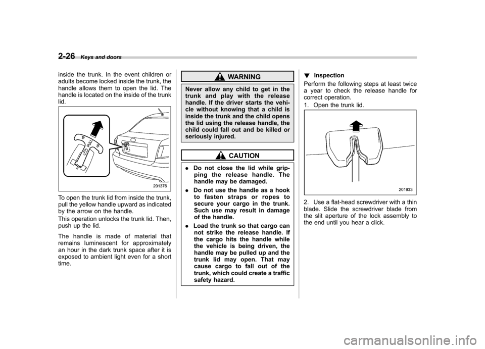
inside the trunk. In the event children or
adults become locked inside the trunk, the
handle allows them to open the lid. The
handle is located on the inside of the trunklid.
To open the trunk lid from inside the trunk,
pull the yellow handle upward as indicated
by the arrow on the handle.
This operation unlocks the trunk lid. Then,
push up the lid.
The handle is made of material that
remains luminescent for approximately
an hour in the dark trunk space after it is
exposed to ambient light even for a shorttime.
WARNING
Never allow any child to get in the
trunk and play with the release
handle. If the driver starts the vehi-
cle without knowing that a child is
inside the trunk and the child opens
the lid using the release handle, the
child could fall out and be killed or
seriously injured.
CAUTION
. Do not close the lid while grip-
ping the release handle. The
handle may be damaged.
. Do not use the handle as a hook
to fasten straps or ropes to
secure your cargo in the trunk.
Such use may result in damage
of the handle.
. Load the trunk so that cargo can
not strike the release handle. If
the cargo hits the handle while
the vehicle is being driven, the
handle may be pulled up and the
trunk lid may open. That may
cause cargo to fall out of the
trunk, which could create a traffic
safety hazard. !
Inspection
Perform the following steps at least twice
a year to check the release handle for
correct operation.
1. Open the trunk lid.
2. Use a flat-head screwdriver with a thin
blade. Slide the screwdriver blade from
the slit aperture of the lock assembly to
the end until you hear a click.
Page 120 of 458

Ignition switch..................................................... 3-3
LOCK .................................................................. 3-3
Acc..................................................................... 3-4
ON...................................................................... 3-4
START ................................................................ 3-4
Key reminder chime ............................................ 3-5
Ignition switch light ............................................. 3-5
Hazard warning flasher ....................................... 3-5
Meters and gauges. ............................................. 3-6
Combination meter illumination ........................... 3-6
Canceling the function for meter/gauge needle movement upon turning on the ignition switch ............................................................... 3-6
Meter/Gauge needle illumination setting (turbo models except STI) ............................................ 3-7
Speedometer ....................................................... 3-8
Odometer/Trip meter ............................................ 3-8
Tachometer ......................................................... 3-9
Fuel gauge ......................................................... 3-10
Temperature gauge (turbo models) ..................... 3-11
REV indicator light and buzzer (STI). ................ 3-11
Setting the alarm-level engine speed ................... 3-12
Deactivating the REV alarm system ..................... 3-13
Warning and indicator lights ............................. 3-13
Seatbelt warning light and chime ........................ 3-14
SRS airbag system warning light ........................ 3-15
Front passenger ’s frontal airbag ON and OFF
indicators ......................................................... 3-16
CHECK ENGINE warning light/Malfunction indicator lamp .................................................. 3-16 Coolant temperature low indicator light (non-
turbo models)/Coolant temperature high
warning light (non-turbo models) ...................... 3-17
Charge warning light .......................................... 3-18
Oil pressure warning light .................................. 3-18
AT OIL TEMP warning light (AT models) .............. 3-18
Rear differential oil temperature warning light (STI) ................................................................ 3-19
Low tire pressure warning light (U.S.-spec. models) ........................................................... 3-19
ABS warning light .............................................. 3-21
Brake system warning light ................................ 3-21
Low fuel warning light ....................................... 3-22
Hill start assist warning light (MT models –if
equipped)/Hill start assist OFF indicator light (STI) ................................................................ 3-22
Door open warning light .................................... 3-23
All-Wheel Drive warning light (AT models) ..... ..... 3-23
Vehicle Dynamics Control operation indicator light ................................................................ 3-23
Vehicle Dynamics Control warning light/Vehicle Dynamics Control OFF indicator light/Traction
Control OFF indicator light (STI) ....................... 3-23
Security indicator light ....................................... 3-25
SPORT mode indicator light (AT models) ............ 3-25
SI-DRIVE indicator light (STI) .............................. 3-26
Shift-up indicator light (STI) ............................... 3-26
Select lever/gear position indicator (AT models) ..................................................... 3-26
Turn signal indicator lights ................................. 3-26
High beam indicator light ................................... 3-26
Cruise control indicator light .............................. 3-26
Instruments and controls
3
Page 123 of 458
3-4Instruments and controls
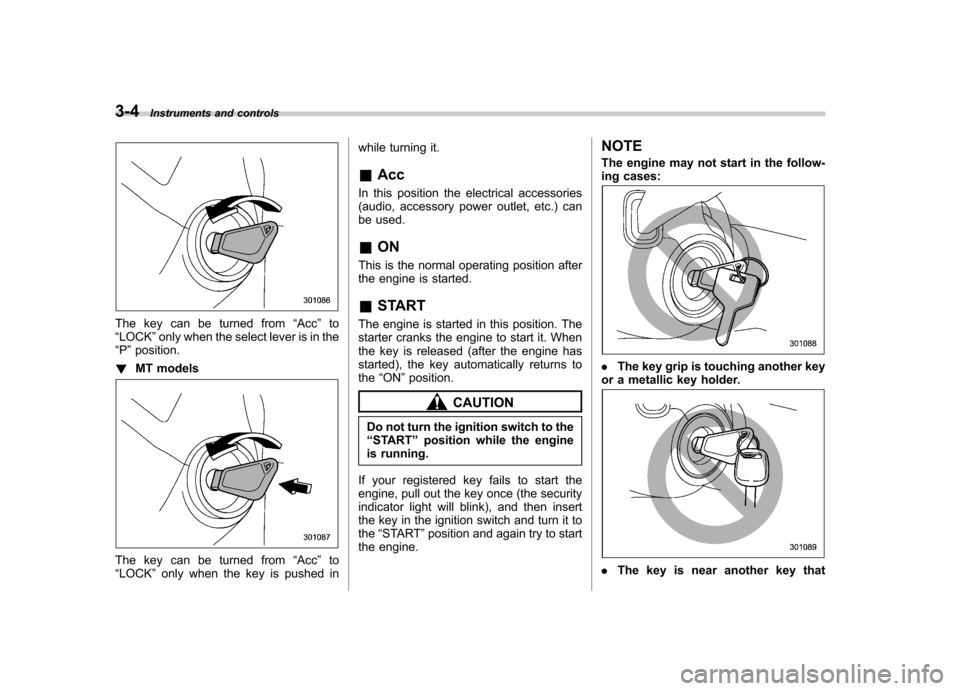
The key can be turned from “Acc ”to
“ LOCK ”only when the select lever is in the
“ P ”position.
! MT models
The key can be turned from “Acc ”to
“ LOCK ”only when the key is pushed in while turning it. &
Acc
In this position the electrical accessories
(audio, accessory power outlet, etc.) can
be used. & ON
This is the normal operating position after
the engine is started. & START
The engine is started in this position. The
starter cranks the engine to start it. When
the key is released (after the engine has
started), the key automatically returns tothe “ON ”position.
CAUTION
Do not turn the ignition switch to the “ START ”position while the engine
is running.
If your registered key fails to start the
engine, pull out the key once (the security
indicator light will blink), and then insert
the key in the ignition switch and turn it tothe “START ”position and again try to start
the engine. NOTE
The engine may not start in the follow-
ing cases:
.
The key grip is touching another key
or a metallic key holder.
. The key is near another key that
Page 134 of 458

The warning light(s) for unfastened
seatbelt(s) will alternate between
steady illumination and flashing at
15-second intervals. The chime will
not sound. –At speeds higher than approxi-
mately 9 mph (15 km/h)
The warning light(s) for unfastened
seatbelt(s) will alternate between
flashing and steady illumination at
15-second intervals and the chime
will sound while the warning light(s)
is/are flashing.
. It is possible to cancel the warning
operation that follows the 6-second
warning after turning ON the ignition
switch. When the ignition switch is
turned ON next time, however, the
complete sequence of the warning
operation resumes. For further details
about canceling the warning operation,
please contact your SUBARU dealer.
If there is no passenger on the front passenger ’s seat, the seatbelt warning
device for the front passenger ’s seat will
be deactivated. The front passenger ’s
occupant detection system monitors
whether or not there is a passenger on
the front passenger ’s seat.
Observe the following precautions. Failure
to do so may prevent the device from
functioning correctly or cause the device to fail. .
Do not install any accessory such as a
table or TV onto the seatback.. Do not store a heavy load in the
seatback pocket.. Do not allow the rear seat occupant to
place his/her hands or legs on the front passenger ’s seatback, or allow him/her to
pull the seatback. . Do not use front seats with their back-
ward-forward position and seatback not
being locked into place securely. If any of
them are not locked securely, adjust them
again. For adjusting procedure, refer to“ Front seats ”F 1-2.
If the seatbelt warning device for the front passenger ’s seat does not function cor-
rectly (e.g., it is activated even when the
front passenger ’s seat is empty or it is
deactivated even when the front passen-
ger has not fastened his/her seatbelt),
take the following actions. . Ensure that no article is placed on the
seat other than a child restraint system
and its child occupant, although we
strongly recommend that all children sit
in the rear seat properly restrained. . Ensure that there is no article left in the
seatback pocket.. Ensure that the backward-forward po-
sition and seatback of front passenger ’s seat are locked into place securely by
moving the seat back and forth.
If still the seatbelt warning device for front passenger
’s seat does not function cor-
rectly after taking relevant corrective ac-
tions described above, immediately con-
tact your SUBARU dealer for an inspec-tion.
& SRS airbag system
warning light
WARNING
If the warning light exhibits any of
the following conditions, there may
be a malfunction in the seatbelt
pretensioners and/or SRS airbag
system. Immediately take your vehi-
cle to your nearest SUBARU dealer
to have the system checked. Unless
checked and properly repaired, the
seatbelt pretensioners and/or SRS
airbag will not operate properly in
the event of a collision, which may
increase the risk of injury. . Flashing or flickering of the warn-
ing light
. No illumination of the warning
light when the ignition switch is
first turned to the “ON ”position
Instruments and controls
3-15
– CONTINUED –
Page 144 of 458
!Traction Control OFF indicator light (green –STI)
The light illuminates when the Vehicle
Dynamics Control mode switch is pressed
briefly. For details, refer to “Traction mode ”
F 7-36.
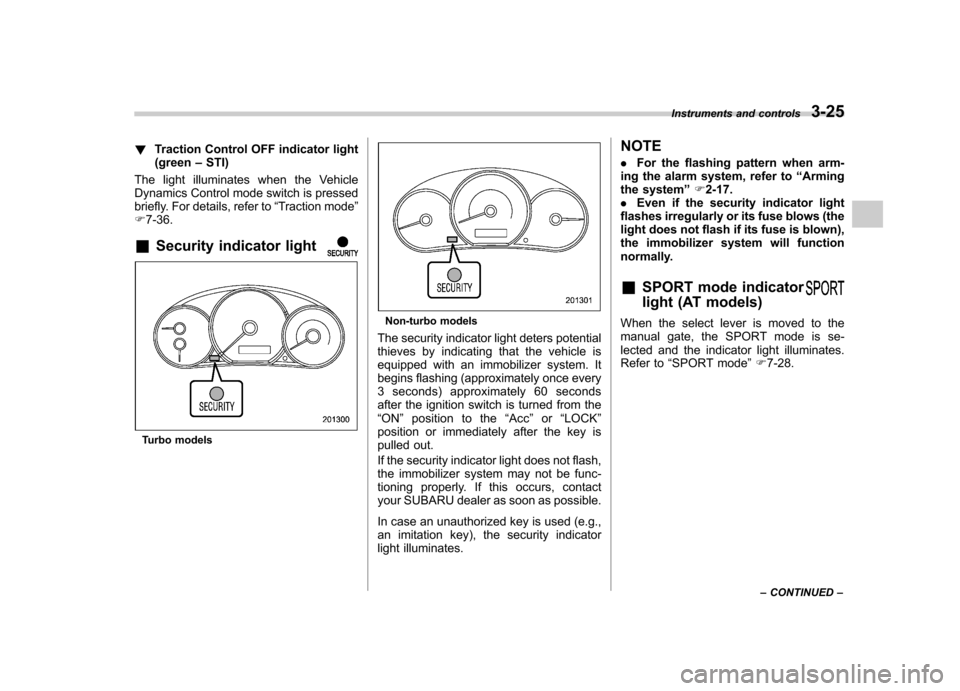
& Security indicator light
Turbo models
Non-turbo models
The security indicator light deters potential
thieves by indicating that the vehicle is
equipped with an immobilizer system. It
begins flashing (approximately once every
3 seconds) approximately 60 seconds
after the ignition switch is turned from the“ ON ”position to the “Acc ”or “LOCK ”
position or immediately after the key is
pulled out.
If the security indicator light does not flash,
the immobilizer system may not be func-
tioning properly. If this occurs, contact
your SUBARU dealer as soon as possible.
In case an unauthorized key is used (e.g.,
an imitation key), the security indicator
light illuminates. NOTE .
For the flashing pattern when arm-
ing the alarm system, refer to “Arming
the system ”F 2-17.
. Even if the security indicator light
flashes irregularly or its fuse blows (the
light does not flash if its fuse is blown),
the immobilizer system will function
normally.
& SPORT mode indicator
light (AT models)When the select lever is moved to the
manual gate, the SPORT mode is se-
lected and the indicator light illuminates.
Refer to “SPORT mode ”F 7-28.
Instruments and controls
3-25
– CONTINUED –
Page 162 of 458
!Compass calibration
1. If a “C ” is displayed in the compass
window, the compass needs to be cali- brated.
2. Drive the vehicle in a circle at 5 mph (8
km/h) or less until the display reads a direction.
3. You can also calibrate the compass by
driving your vehicle on your everyday
routine. The compass will be calibrated
once it has tracked a complete circle.
4. To recalibrate your compass, push and
hold the compass display button for 9
seconds until a “C ” appears in the
compass window.
5. Calibrate the compass according to
step 2 or step 3. ! HomeLink
®Wireless Control Sys-
tem
The HomeLink
®Wireless Control System
can be used to activate remote control
devices such as gate operators, garage
door openers, door locks, home lighting
and security systems.
There are three HomeLink
®buttons on the
mirror, each of which can be programmed
for operation of one desired device. For
details on the device types which can be
operated by this system, consult the HomeLink
®website at: www.homelink.com or call 1-800-355-3515.
Note the following information about this system.
Ifyourvehicleisequippedwiththe HomeLink
®Wireless Control System, it
complies with Part 15 of the Federal
Communications Commission Rules in
the U.S. and the RSS-210 of Industry
Canada in Canada. Its operation is subject
to the following two conditions:
(1) this device may not cause harmful
interference, and (2) this device must
accept any interference received, includ-
ing interference that may cause undesiredoperation.
Changes and modifications to this system
by anyone other than an authorized
service facility could void authorization to
use this equipment. HomeLink
®and the HomeLink®house are
registered trademarks of Johnson Con-
trols, Inc.
WARNING
. When programming the
HomeLink
®Wireless Control Sys-
tem, you may be operating a
garage door opener or other
device. Make sure that people and objects are out of the way of
the garage door or other device
to prevent potential harm ordamage.
. Do not use the HomeLink
®Wire-
less Control System with a gar-
age door opener that lacks the
safety stop and reverse feature
as required by applicable safety
standards. A garage door opener
which cannot detect an object,
signaling the door to stop and
reverse, does not meet these
safety standards. Using a garage
door opener without these fea-
tures increases risk of serious
injury or death. For more infor-
mation, consult the HomeLink
®website at www.homelink.com or
call 1-800-355-3515.
CAUTION
When programming the HomeLink
®Wireless Control System to operate
a garage door opener or an entrance
gate, unplug the device ’s motor
from the outlet during programming
to prevent motor burnout. Instruments and controls
3-43
– CONTINUED –
Page 165 of 458
3-46Instruments and controls
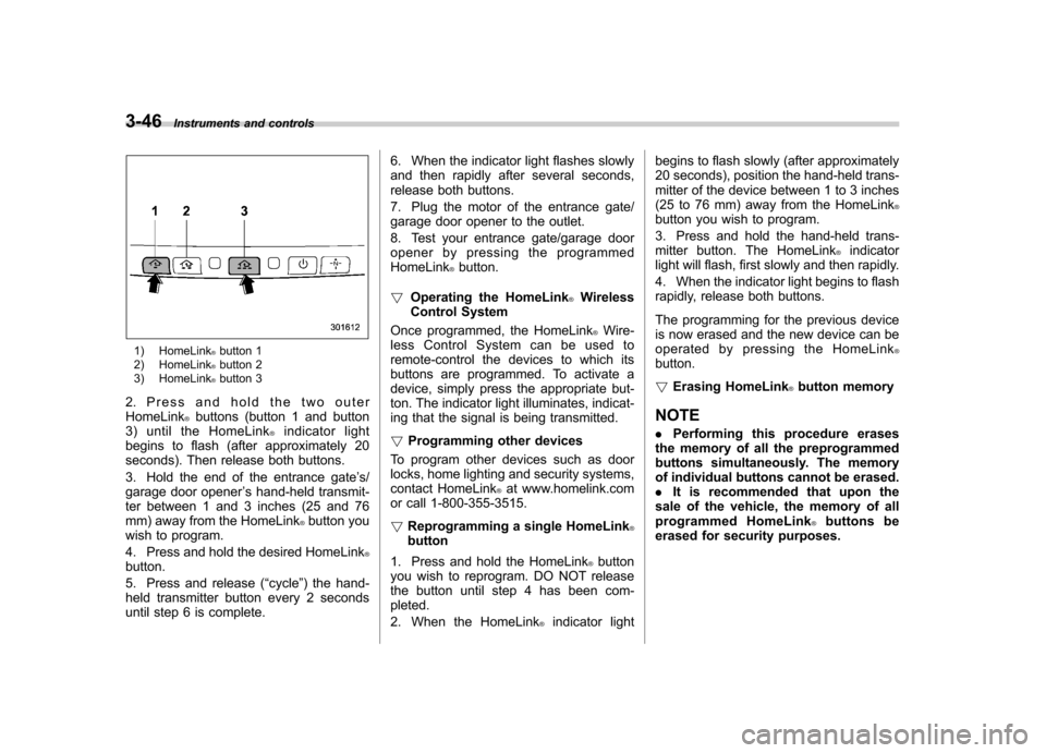
1) HomeLink®button 1
2) HomeLink®button 2
3) HomeLink®button 3
2. Press and hold the two outer HomeLink
®buttons (button 1 and button
3) until the HomeLink®indicator light
begins to flash (after approximately 20
seconds). Then release both buttons.
3. Hold the end of the entrance gate ’s/
garage door opener ’s hand-held transmit-
ter between 1 and 3 inches (25 and 76
mm) away from the HomeLink
®button you
wish to program.
4. Press and hold the desired HomeLink
®button.
5. Press and release ( “cycle ”) the hand-
held transmitter button every 2 seconds
until step 6 is complete. 6. When the indicator light flashes slowly
and then rapidly after several seconds,
release both buttons.
7. Plug the motor of the entrance gate/
garage door opener to the outlet.
8. Test your entrance gate/garage door
opener by pressing the programmedHomeLink
®button.
! Operating the HomeLink
®Wireless
Control System
Once programmed, the HomeLink
®Wire-
less Control System can be used to
remote-control the devices to which its
buttons are programmed. To activate a
device, simply press the appropriate but-
ton. The indicator light illuminates, indicat-
ing that the signal is being transmitted. ! Programming other devices
To program other devices such as door
locks, home lighting and security systems,
contact HomeLink
®at www.homelink.com
or call 1-800-355-3515. ! Reprogramming a single HomeLink
®button
1. Press and hold the HomeLink
®button
you wish to reprogram. DO NOT release
the button until step 4 has been com-pleted.
2. When the HomeLink
®indicator light begins to flash slowly (after approximately
20 seconds), position the hand-held trans-
mitter of the device between 1 to 3 inches
(25 to 76 mm) away from the HomeLink
®button you wish to program.
3. Press and hold the hand-held trans-
mitter button. The HomeLink
®indicator
light will flash, first slowly and then rapidly.
4. When the indicator light begins to flash
rapidly, release both buttons.
The programming for the previous device
is now erased and the new device can be
operated by pressing the HomeLink
®button. ! Erasing HomeLink
®button memory
NOTE . Performing this procedure erases
the memory of all the preprogrammed
buttons simultaneously. The memory
of individual buttons cannot be erased.. It is recommended that upon the
sale of the vehicle, the memory of all
programmed HomeLink
®buttons be
erased for security purposes.
Page 169 of 458
3-50Instruments and controls
CAUTION
. To prevent the battery from being
discharged, do not operate the
defogger and deicer system con-
tinuously for any longer than
necessary.
. Do not use sharp instruments or
window cleaner containing abra-
sives to clean the inner surface
of the rear window. They may
damage the conductors printed
on the window.
NOTE . Turn on the defogger and deicer
system if the wipers are frozen to the windshield.. If the windshield is covered with
snow, remove the snow so that the
windshield wiper deicer works effec-
tively.. While the defogger and deicer sys-
tem is in the continuous operation
mode, if the vehicle speed remains at
9 mph (15 km/h) or less for 15 minutes,
the windshield wiper deicer automati-
cally stops operating, though the rear
window defogger and outside mirror
defogger maintain continuous opera-
tion in this condition. Tilt/telescopic steering wheel
WARNING
. Do not adjust the steering wheel
tilt/telescopic position while driv-
ing. This may cause loss of
vehicle control and result in
personal injury.
. If the lever cannot be raised to
the fixed position, adjust the
steering wheel again. It is dan-
gerous to drive without locking
the steering wheel. This may
cause loss of vehicle control
and result in personal injury.
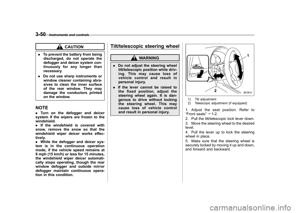
1) Tilt adjustment
2) Telescopic adjustment (if equipped)
1. Adjust the seat position. Refer to “ Front seats ”F 1-2.
2. Pull the tilt/telescopic lock lever down.
3. Move the steering wheel to the desired level.
4. Pull the lever up to lock the steering
wheel in place.
5. Make sure that the steering wheel is
securely locked by moving it up and down,
and forward and backward.