2011 SUBARU IMPREZA child lock
[x] Cancel search: child lockPage 110 of 458

your vehicle. Examples:–Vibration from a construction site
– Vibration in a multistory car park
– Vibration from trains
. You can have the sensitivity of the
shock sensors adjusted to your pre-
ference by your SUBARU dealer. Child safety locks
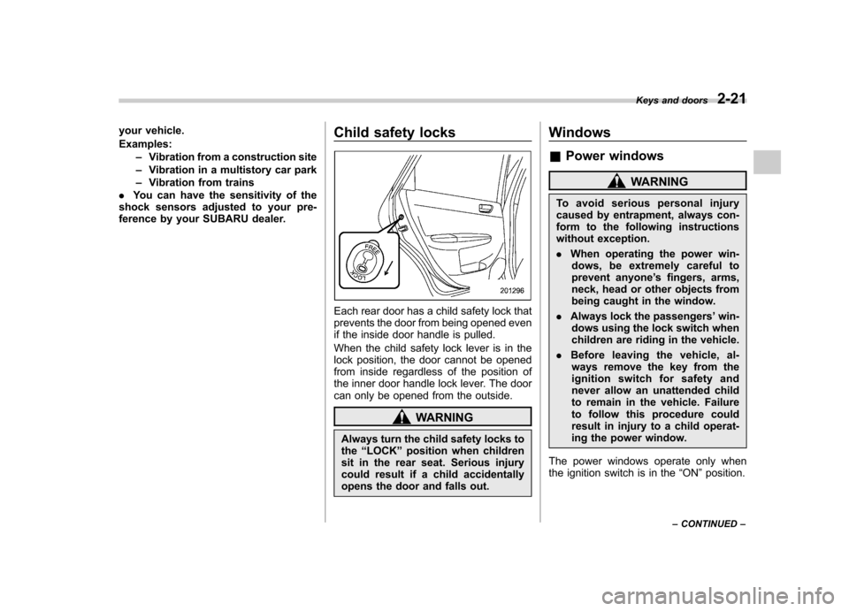
Each rear door has a child safety lock that
prevents the door from being opened even
if the inside door handle is pulled.
When the child safety lock lever is in the
lock position, the door cannot be opened
from inside regardless of the position of
the inner door handle lock lever. The door
can only be opened from the outside.
WARNING
Always turn the child safety locks to the “LOCK ”position when children
sit in the rear seat. Serious injury
could result if a child accidentally
opens the door and falls out. Windows &
Power windows
WARNING
To avoid serious personal injury
caused by entrapment, always con-
form to the following instructions
without exception. . When operating the power win-
dows, be extremely careful to
prevent anyone ’s fingers, arms,
neck, head or other objects from
being caught in the window.
. Always lock the passengers ’win-
dows using the lock switch when
children are riding in the vehicle.
. Before leaving the vehicle, al-
ways remove the key from the
ignition switch for safety and
never allow an unattended child
to remain in the vehicle. Failure
to follow this procedure could
result in injury to a child operat-
ing the power window.
The power windows operate only when
the ignition switch is in the “ON ”position.
Keys and doors
2-21
– CONTINUED –
Page 114 of 458

Trunk lid (4-door)
WARNING
. To prevent dangerous exhaust
gas from entering the vehicle,
always keep the trunk lid closed
while driving.
. Help prevent children, adults or
animals from locking themselves
in the trunk. On hot or sunny
days, the temperature in the
trunk could quickly become high
enough to cause death or serious
heat-related injuries including
brain damage to anyone locked
inside, particularly for small chil-dren.
. When leaving the vehicle, either
close all windows and lock all
doors. Also make certain that the
trunk is closed. &
To open and close the trunk
lid from outside
The trunk lid can be opened using the
remote keyless entry system. Refer to“ Remote keyless entry system ”F 2-8.
To close the trunk lid, lightly press the
trunk lid down until the latch engages.
NOTE
Do not leave your valuables in the
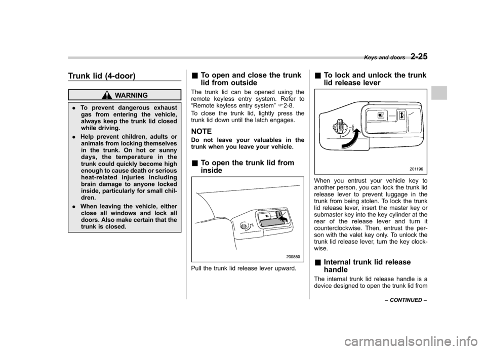
trunk when you leave your vehicle. & To open the trunk lid from inside
Pull the trunk lid release lever upward. &
To lock and unlock the trunk
lid release lever
When you entrust your vehicle key to
another person, you can lock the trunk lid
release lever to prevent luggage in the
trunk from being stolen. To lock the trunk
lid release lever, insert the master key or
submaster key into the key cylinder at the
rear of the release lever and turn it
counterclockwise. Then, entrust the per-
son with the valet key only. To unlock the
trunk lid release lever, turn the key clock-wise. &Internal trunk lid release handle
The internal trunk lid release handle is a
device designed to open the trunk lid from Keys and doors
2-25
– CONTINUED –
Page 115 of 458

2-26Keys and doors
inside the trunk. In the event children or
adults become locked inside the trunk, the
handle allows them to open the lid. The
handle is located on the inside of the trunklid.
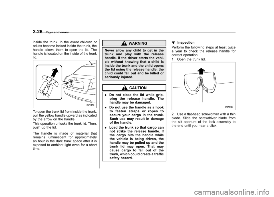
To open the trunk lid from inside the trunk,
pull the yellow handle upward as indicated
by the arrow on the handle.
This operation unlocks the trunk lid. Then,
push up the lid.
The handle is made of material that
remains luminescent for approximately
an hour in the dark trunk space after it is
exposed to ambient light even for a shorttime.
WARNING
Never allow any child to get in the
trunk and play with the release
handle. If the driver starts the vehi-
cle without knowing that a child is
inside the trunk and the child opens
the lid using the release handle, the
child could fall out and be killed or
seriously injured.
CAUTION
. Do not close the lid while grip-
ping the release handle. The
handle may be damaged.
. Do not use the handle as a hook
to fasten straps or ropes to
secure your cargo in the trunk.
Such use may result in damage
of the handle.
. Load the trunk so that cargo can
not strike the release handle. If
the cargo hits the handle while
the vehicle is being driven, the
handle may be pulled up and the
trunk lid may open. That may
cause cargo to fall out of the
trunk, which could create a traffic
safety hazard. !
Inspection
Perform the following steps at least twice
a year to check the release handle for
correct operation.
1. Open the trunk lid.
2. Use a flat-head screwdriver with a thin
blade. Slide the screwdriver blade from
the slit aperture of the lock assembly to
the end until you hear a click.
Page 122 of 458

Ignition switch
WARNING
. Never turn the ignition switch to
“ LOCK ”while the vehicle is
being driven or towed because
that will lock the steering wheel,
preventing steering control. And
when the engine is turned off, it
takes a much greater effort than
usual to steer.
. Before leaving the vehicle, al-
ways remove the key from the
ignition switch for safety and
never allow an unattended child
to remain in the vehicle. Failure
to follow this procedure could
result in injury to a child or
others. Children could operate
the power windows, the moon-
roof or other controls or even
make the vehicle move.
CAUTION
Do not attach a large key holder or
key case to either key. If it banged
against your knees or hands while
you are driving, it could turn the
ignition switch from the “ON ”posi- tion to the
“Acc ”or “LOCK ”posi-
tion, thereby stopping the engine.
Also, if the key is attached to a
keyholder or to a large bunch of
other keys, centrifugal force may act
on it as the vehicle moves, resulting
in unwanted turning of the ignitionswitch.
The ignition switch has four positions:
LOCK, Acc, ON and START. NOTE . Keep the ignition switch in the
“ LOCK ”position when the engine is
not running. . Using electrical accessories for a
long time with the ignition switch in the“ ON ”or “Acc ”position can cause the battery to go dead..
If the ignition switch will not move
from the “LOCK ”position to the “Acc ”
position, turn the steering wheel
slightly to the left and right as you turn
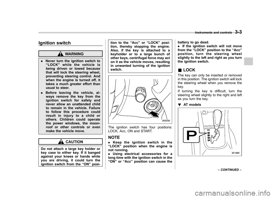
the ignition switch. & LOCK
The key can only be inserted or removed
in this position. The ignition switch will lock
the steering wheel when you remove the
key.
If turning the key is difficult, turn the
steering wheel slightly to the right and left
as you turn the key. ! AT models
Instruments and controls 3-3
– CONTINUED –
Page 134 of 458

The warning light(s) for unfastened
seatbelt(s) will alternate between
steady illumination and flashing at
15-second intervals. The chime will
not sound. –At speeds higher than approxi-
mately 9 mph (15 km/h)
The warning light(s) for unfastened
seatbelt(s) will alternate between
flashing and steady illumination at
15-second intervals and the chime
will sound while the warning light(s)
is/are flashing.
. It is possible to cancel the warning
operation that follows the 6-second
warning after turning ON the ignition
switch. When the ignition switch is
turned ON next time, however, the
complete sequence of the warning
operation resumes. For further details
about canceling the warning operation,
please contact your SUBARU dealer.
If there is no passenger on the front passenger ’s seat, the seatbelt warning
device for the front passenger ’s seat will
be deactivated. The front passenger ’s
occupant detection system monitors
whether or not there is a passenger on
the front passenger ’s seat.
Observe the following precautions. Failure
to do so may prevent the device from
functioning correctly or cause the device to fail. .
Do not install any accessory such as a
table or TV onto the seatback.. Do not store a heavy load in the
seatback pocket.. Do not allow the rear seat occupant to
place his/her hands or legs on the front passenger ’s seatback, or allow him/her to
pull the seatback. . Do not use front seats with their back-
ward-forward position and seatback not
being locked into place securely. If any of
them are not locked securely, adjust them
again. For adjusting procedure, refer to“ Front seats ”F 1-2.
If the seatbelt warning device for the front passenger ’s seat does not function cor-
rectly (e.g., it is activated even when the
front passenger ’s seat is empty or it is
deactivated even when the front passen-
ger has not fastened his/her seatbelt),
take the following actions. . Ensure that no article is placed on the
seat other than a child restraint system
and its child occupant, although we
strongly recommend that all children sit
in the rear seat properly restrained. . Ensure that there is no article left in the
seatback pocket.. Ensure that the backward-forward po-
sition and seatback of front passenger ’s seat are locked into place securely by
moving the seat back and forth.
If still the seatbelt warning device for front passenger
’s seat does not function cor-
rectly after taking relevant corrective ac-
tions described above, immediately con-
tact your SUBARU dealer for an inspec-tion.
& SRS airbag system
warning light
WARNING
If the warning light exhibits any of
the following conditions, there may
be a malfunction in the seatbelt
pretensioners and/or SRS airbag
system. Immediately take your vehi-
cle to your nearest SUBARU dealer
to have the system checked. Unless
checked and properly repaired, the
seatbelt pretensioners and/or SRS
airbag will not operate properly in
the event of a collision, which may
increase the risk of injury. . Flashing or flickering of the warn-
ing light
. No illumination of the warning
light when the ignition switch is
first turned to the “ON ”position
Instruments and controls
3-15
– CONTINUED –
Page 276 of 458

not. Remote engine start transmitter pro-
gramming and feature programming can
be adjusted using the following procedure.
1. Open the driver’s door (the driver ’s
door must remain opened throughout the
entire process).
2. Insert the key into the vehicle ’s ignition
switch and turn to the “ON ”position.
3. Locate the small black programming
button behind the fuse box cover, on the
driver ’s side left under the dashboard
panel.
4. Press and hold the black programming
button for 10 to 15 seconds. The horn will
honk and the turn signal lights will flash
three times to indicate that the system has
entered programming mode. At this point
you can proceed to either step 5 or step 6.
5. To program a remote engine start
transmitter: press and release the “
”
button on each transmitter. The horn will
honk and the turn signal lights will flash
one time to indicate a successful trans-
mitter learn each time the “
”button is
pressed. You can program up to eight transmitters.
6. To toggle the Horn Confirmation chirps
ON/OFF: depress and release the brake
pedal to toggle the feature. The horn will
chirp and the turn signal lights will flash
one time to indicate Confirmation Horn
Chirps are “OFF ”. The horn will honk and the turn signal lights will flash 2 times to
indicate Confirmation Horn Chirps are“
ON ”. Depressing the brake pedal repeat-
edly will toggle the feature ON or OFF
each time.
7. To exit the remote engine start trans-
mitter and feature programming mode,
turn the ignition switch to the “LOCK ”
position, remove the key from the ignition
switch and test operation of the remote
engine start transmitter(s) and horn con-
firmation feature.
& System maintenance
! Changing the batteries
CAUTION
. Do not let dust, oil or water get on
or in the remote engine start
transmitter when replacing the
battery.
. Be careful not to damage the
printed circuit board in the re-
mote engine start transmitter
when replacing the battery.
. Be careful not to allow children to
touch the battery and any re-
moved parts; children could
swallow them.
. There is a danger of explosion if an incorrect replacement battery
is used. Replace only with the
same or equivalent type of bat-
tery.
. Batteries should not be exposed
to excessive heat such as sun-
shine, fire or the like.
The two 3-volt lithium batteries (modelCR-1220 ) supplied in your remote engine
start transmitter should last approximately
3 years, depending on usage. When the
batteries begin to weaken, you will notice
a decrease in range (distance from the
vehicle that your remote engine start
system operates). Follow the instructions
below to change the remote engine start
transmitter batteries.
Starting and operating 7-13
– CONTINUED –
Page 304 of 458

When parking on a hill, always turn the
steering wheel. When the vehicle is
headed up the hill, the front wheels should
be turned away from the curb.
When facing downhill, the front wheels
should be turned into the curb.
WARNING
. Never leave unattended children
or pets in the vehicle. They could
accidentally injure themselves or
others through inadvertent op-
eration of the vehicle. Also, on
hot or sunny days, the tempera-
ture in a closed vehicle could
quickly become high enough to
cause severe or possibly fatal
injuries to people.
. Do not park the vehicle over
flammable materials such as dry
grass, waste paper or rags, as
they may burn easily if they come
near hot engine or exhaust sys-
tem parts.
. Be sure to stop the engine if you
take a nap in the vehicle. If
engine exhaust gas enters the
passenger compartment, occu-
pants in the vehicle could die
from carbon monoxide (CO) con-
tained in the exhaust gas.
CAUTION
If your vehicle has a front under-
spoiler and rear underspoiler (both
optional), pay attention to blocks and other obstructions on the
ground when parking. The under-
spoilers could be damaged by con-
tact with them.
Starting and operating
7-41
Page 448 of 458

Parking........................................................ 7-40, 11-31
Pedal .................................................................. 11-28
System ................................................................. 7-31
Brake pedal Free play ............................................................. 11-28
Reserve distance .................................................. 11-28
Brake system ............................................................ 7-31
Warning light ......................................................... 3-21
Braking ..................................................................... 7-31
Tips...................................................................... 7-31
Breaking-in of new brake pads and linings ................... 11-30
Bulb Chart .................................................................. 12-16
Replacing ............................................................. 11-47
C
Cargo area Cover ................................................................... 6-12
Light ............................................................. 6-2, 11-54
Tie-down hooks ..................................................... 6-13
Catalytic converter ....................................................... 8-3
Center Console .................................................................. 6-5
Ventilators ............................................................... 4-3
Center and side ventilators ............................................ 4-3
Changing
Coolant ................................................................ 11-15
Flat tire ................................................................... 9-6
Oil and oil filter ..................................................... 11-11
Charge warning light .................................................. 3-18 CHECK ENGINE warning light/Malfunction indicator
lamp ...................................................................... 3-16
Checking
Brake pedal free play ............................................ 11-28
Brake pedal reserve distance ................................. 11-28
Clutch function ..................................................... 11-29
Clutch pedal free play ........................................... 11-29
Coolant level ........................................................ 11-14
Fluid level (automatic transmission fluid) .................. 11-22
Fluid level (brake fluid) .......................................... 11-25
Fluid level (clutch fluid) .......................................... 11-26
Fluid level (power steering fluid) .. ........................... 11-24
Fluid level (washer fluid) ........................................ 11-38
Oil level (engine oil) .............................................. 11-10
Oil level (front differential gear oil) .......................... 11-23
Oil level (manual transmission oil) .......................... 11-21
Child restraint systems ................................................ 1-21
Installation of a booster seat .................................... 1-27
Installation with A/ELR seatbelt ... ............................. 1-24
Lower and tether anchorages ................................... 1-29
Top tether anchorages ............................................ 1-31
Child safety ................................................................... 5
Locks .................................................................... 2-21
Chime Key........................................................................ 3-5Light ..................................................................... 3-31
Seatbelt. ................................................................ 3-14
Cleaning Aluminum wheels ................................................... 10-3
Interior .................................................................. 10-5
Ventilation grille ...................................................... 4-12 Index
14-3