2011 SUBARU IMPREZA set clock
[x] Cancel search: set clockPage 121 of 458

Instruments and controlsCruise control set indicator light ......................... 3-27
Front fog light indicator light (if equipped) .......... 3-27
Headlight indicator light (if equipped) ................. 3-27
Driver ’s control center differential auto indicator
light (STI) ......................................................... 3-27
Driver ’s control center differential indicator and
warning lights (STI) .......................................... 3-27
REV indicator light (STI) ..................................... 3-28
Clock ................................................................... 3-28
Information display ............................................ 3-29
Outside temperature indicator ............................ 3-29
Current fuel consumption (if equipped) ............... 3-30
Average fuel consumption .................................. 3-30
Turn off display of fuel consumption indicator .......................................................... 3-31
Light control switch ........................................... 3-31
Headlights. ......................................................... 3-32
High/low beam change (dimmer) ......................... 3-32
Headlight flasher ................................................ 3-32 Daytime running light system
............................. 3-33
Turn signal lever ................................................ 3-33
Illumination brightness control ......................... 3-33
Headlight beam leveler (if equipped) ............... 3-34
Front fog light switch (if equipped) .................. 3-36
Wiper and washer .............................................. 3-36
Windshield wiper and washer switches .............. 3-38
Rear window wiper and washer switch –
5-door ............................................................. 3-39
Mirrors ................................................................ 3-40
Inside mirror ...................................................... 3-40
Auto-dimming mirror/compass (if equipped) ....... 3-40
Auto-dimming mirror/compass with HomeLink
®(if equipped) .................................................... 3-41
Outside mirrors ................................................. 3-47
Defogger and deicer .......................................... 3-48
Tilt/telescopic steering wheel ........................... 3-50
Horn .................................................................... 3-51
Page 147 of 458

3-28Instruments and controls
!Warning light
All the indicator lights will flash in the event
that the driver ’s control center differential
has a malfunction. Have the vehicle
inspected by your SUBARU dealer. For
details, refer to “Driver ’s Control Center
Differential (DCCD) (STI) ”F 7-18.
& REV indicator light (STI)
This light illuminates when the engine
speed reaches a level set by driver or
when the tachometer needle enters the
red zone. Clock
The time changes by 1 minute each time the
“+ ” button or “� ” button is pressed.
Pressing the “+ ” button moves the dis-
played time forward, while pressing the “� ”
button moves the displayed time back.
Pressing and holding either button
changes the displayed time continuously.
CAUTION
To ensure safety, do not attempt to
set the time while driving, as an
accident from inadequate attention
to the road could result.
NOTE
If the battery is disconnected, the time
will be erased. After reconnecting the
battery, set the correct time.
Page 150 of 458
corresponding to that trip meter indica-
tion is not shown until the vehicle has
subsequently covered a distance of 1
mile (or 1 km). &Turn off display of fuel con-
sumption indicator
The display of the fuel consumption
indicator can be turned off.
To turn off the display of the indicator, turn
the ignition switch to the “LOCK ”position
and press the “+ ” button adjacent to the
information display for approximately 5
seconds. Then, the information display
and the clock display will blink for 3
seconds to notify that the display of the
fuel consumption has been turned off.
To restore the indicator, once again pressthe “+ ” button for approximately 5 sec-
onds. NOTE . The initial display setting of the fuel
consumption indicator of your vehicle
has been set to operational at the time
of shipment from the factory. . The average fuel consumption is
calculated even while the indicator is
not displayed.. Even if you turn off the fuel con-
sumption indicator, the fuel consump-
tion indicator will automatically turn on when the battery voltage is discon-
nected and then reconnected for bat-
tery replacement or fuse replacement.
Light control switch
The light control switch operates when the
key is inserted into the ignition switch.
Regardless of the position of the light
control switch, the illuminated lights are
turned off when the key is removed from
the ignition switch. NOTE
Even if the key is removed from the
ignition switch, the lights can be illu-
minated by operating the light control
switch from
“OFF ”to the “
”or “”
position. In this case, if the driver ’s
door is opened, a chirp sound will
inform the driver that the lights are illuminated.
CAUTION
. Use of any lights for a long period
of time while the engine is not
running can cause the battery todischarge.
. Before leaving the vehicle, make
sure that the light control switch
is turned to the “OFF ”position. If
the vehicle is left unattended for
a long time with the light control
switch set to a position otherthan “OFF ”, the battery may be
Instruments and controls
3-31
– CONTINUED –
Page 180 of 458
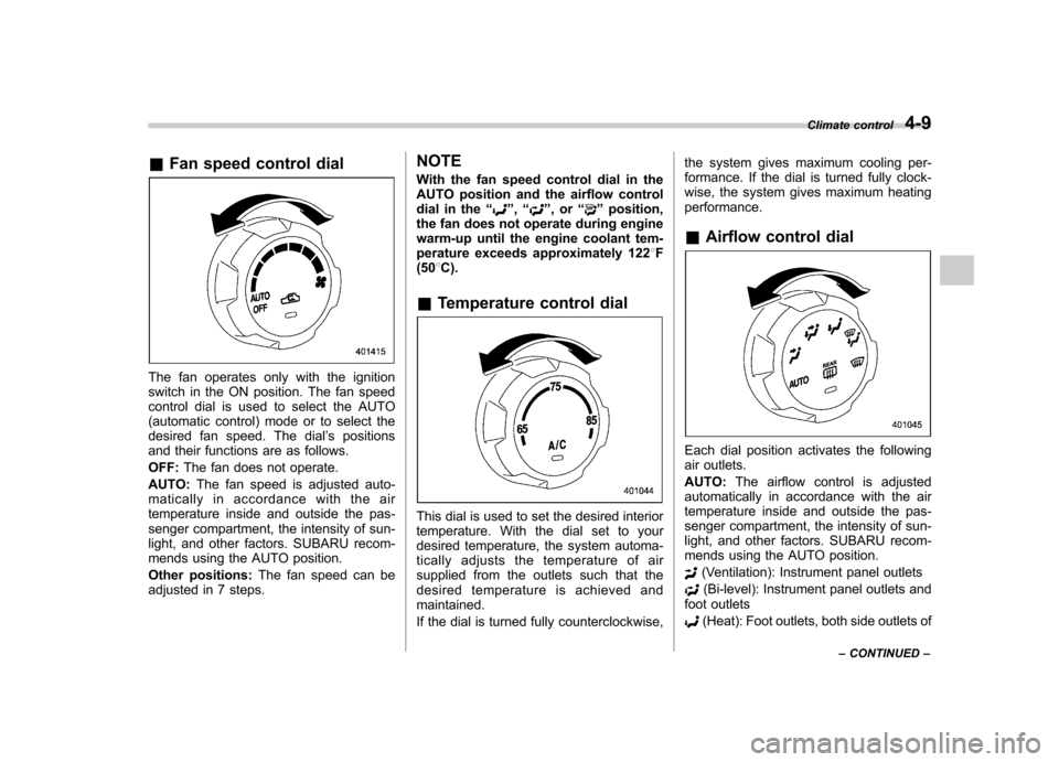
&Fan speed control dial
The fan operates only with the ignition
switch in the ON position. The fan speed
control dial is used to select the AUTO
(automatic control) mode or to select the
desired fan speed. The dial ’s positions
and their functions are as follows. OFF: The fan does not operate.
AUTO: The fan speed is adjusted auto-
maticallyinaccordancewiththeair
temperature inside and outside the pas-
senger compartment, the intensity of sun-
light, and other factors. SUBARU recom-
mends using the AUTO position.
Other positions: The fan speed can be
adjusted in 7 steps. NOTE
With the fan speed control dial in the
AUTO position and the airflow control
dial in the
“
”, “”,or “”position,
the fan does not operate during engine
warm-up until the engine coolant tem-
perature exceeds approximately 122 8F
(50 8C).
& Temperature control dial
This dial is used to set the desired interior
temperature. With the dial set to your
desired temperature, the system automa-
tically adjusts the temperature of air
supplied from the outlets such that the
desired temperature is achieved andmaintained.
If the dial is turned fully counterclockwise, the system gives maximum cooling per-
formance. If the dial is turned fully clock-
wise, the system gives maximum heatingperformance. &
Airflow control dial
Each dial position activates the following
air outlets. AUTO: The airflow control is adjusted
automatically in accordance with the air
temperature inside and outside the pas-
senger compartment, the intensity of sun-
light, and other factors. SUBARU recom-
mends using the AUTO position.
(Ventilation): Instrument panel outlets
(Bi-level): Instrument panel outlets and
foot outlets
(Heat): Foot outlets, both side outlets of Climate control
4-9
– CONTINUED –
Page 198 of 458
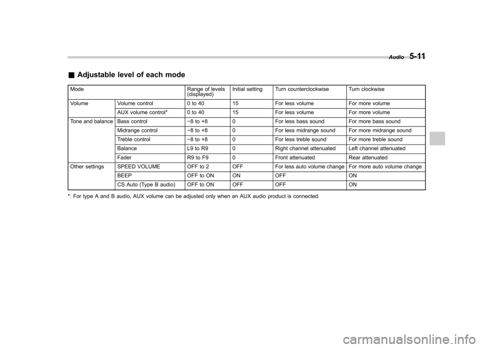
&Adjustable level of each mode
Mode Range of levels (displayed)Initial setting Turn counterclockwise Turn clockwise
Volume Volume control 0 to 40 15 For less volume For more volume AUX volume control* 0 to 40 15 For less volume For more volume
Tone and balance Bass control �8 to +8 0 For less bass sound For more bass sound
Midrange control �8 to +8 0 For less midrange sound For more midrange sound
Treble control �8 to +8 0 For less treble sound For more treble sound
Balance L9 to R9 0 Right channel attenuated Left channel attenuated
Fader R9 to F9 0 Front attenuated Rear attenuated
Other settings SPEED VOLUME OFF to 2 OFF For less auto volume change For more auto volume change
BEEP OFF to ON ON OFF ON
CS Auto (Type B audio) OFF to ON OFF OFF ON
*: For type A and B audio, AUX volume can be adjusted only when an AUX audio product is connected. Audio
5-11
Page 269 of 458

7-6Starting and operating
3. Set the fuel filler cap on the cap holder
inside the fuel filler lid (turbo models).
4. Hook the cord that is attached to the
fuel filler cap onto the hook inside the fuel
filler lid (non-turbo models).
WARNING
. When refueling, insert the fuel
nozzle securely into the fuel filler
pipe. If the nozzle is lifted or not
fully inserted, its automatic stop-
ping mechanism may not func-
tion, causing fuel to overflow the
tank and creating a fire hazard.
. Stop refueling when the auto-
matic stop mechanism on the
fuel nozzle activates. If you con-
tinue to add fuel, temperature
changes or other conditions
may cause fuel to overflow from
the tank and create a fire hazard.
5. Stop filling the tank after the fuel filler
pump automatically stops. Do not add any
more fuel.
6. Put the cap back on, turn it clockwise
until you hear a clicking noise. Be certain
not to catch the tether under the cap whiletightening.
7. Close the fuel filler lid completely.
If you spill any fuel on the painted surface,
rinse it off immediately. Otherwise, the
painted surface could be damaged. NOTE .
You will see the “”sign in the fuel
gauge. This indicates that the fuel filler
door (lid) is located on the right side of
the vehicle.. If the fuel filler cap is not tightened
until it clicks or if the tether is caught
under the cap, the CHECK ENGINE
warning light/malfunction indicator
lamp may illuminate. Refer to “CHECK
ENGINE warning light/Malfunction in-
dicator lamp ”F 3-16.
CAUTION
. Never add any cleaning agents to
the fuel tank. The addition of a
cleaning agent may cause da-
mage to the fuel system.
. After refueling, turn the cap to the
right until it clicks to ensure that
it is fully tightened. If the cap is
not securely tightened, fuel may
leak out while the vehicle is being
driven or fuel spillage could
occur in the event of an accident,
creating a fire hazard.
. Do not let fuel spill on the exterior
surfaces of the vehicle. Because
fuel may damage the paint, be
sure to wipe off any spilled fuel
quickly. Paint damage caused by
Page 401 of 458
11-48Maintenance and service
Left-hand side
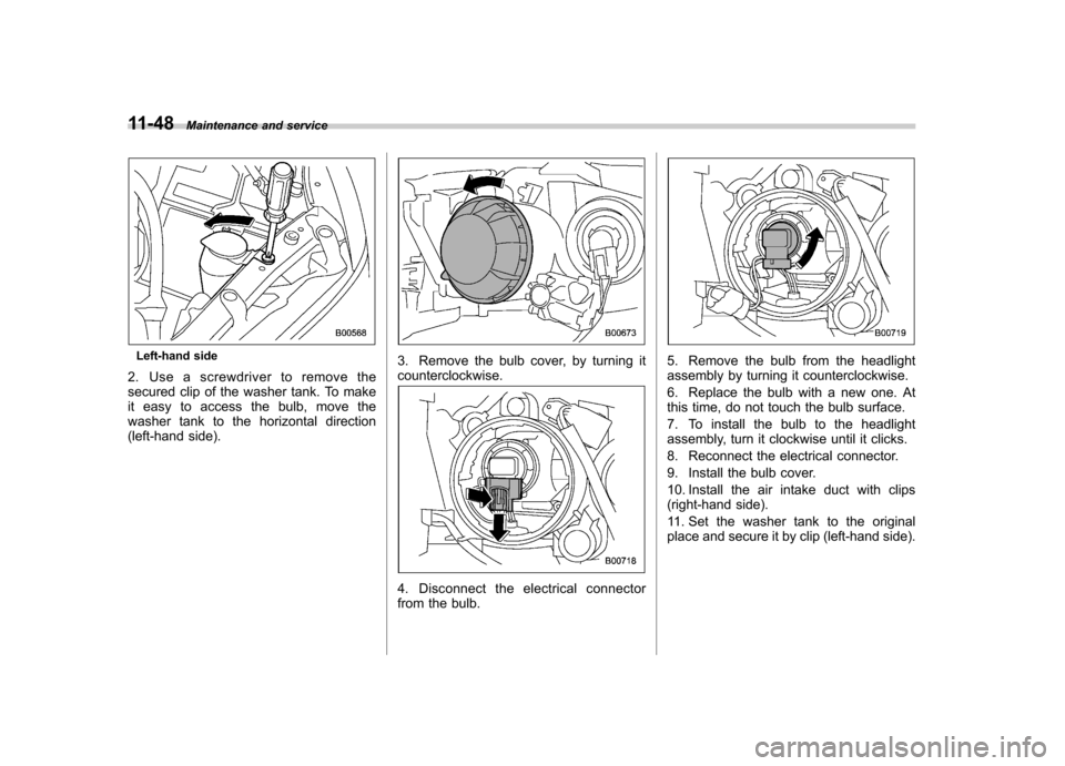
2. Use a screwdriver to remove the
secured clip of the washer tank. To make
it easy to access the bulb, move the
washer tank to the horizontal direction
(left-hand side).3. Remove the bulb cover, by turning it counterclockwise.
4. Disconnect the electrical connector
from the bulb.
5. Remove the bulb from the headlight
assembly by turning it counterclockwise.
6. Replace the bulb with a new one. At
this time, do not touch the bulb surface.
7. To install the bulb to the headlight
assembly, turn it clockwise until it clicks.
8. Reconnect the electrical connector.
9. Install the bulb cover.
10. Install the air intake duct with clips
(right-hand side).
11. Set the washer tank to the original
place and secure it by clip (left-hand side).
Page 402 of 458
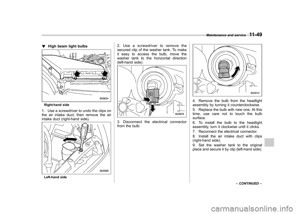
!High beam light bulbs
Right-hand side
1. Use a screwdriver to undo the clips on
the air intake duct, then remove the air
intake duct (right-hand side).
Left-hand side 2. Use a screwdriver to remove the
secured clip of the washer tank. To make
it easy to access the bulb, move the
washer tank to the horizontal direction
(left-hand side).
3. Disconnect the electrical connector
from the bulb.
4. Remove the bulb from the headlight
assembly by turning it counterclockwise.
5. Replace the bulb with new one. At this
time, use care not to touch the bulbsurface.
6. To install the bulb to the headlight
assembly, turn it clockwise until it clicks.
7. Reconnect the electrical connector.
8. Install the air intake duct with clips
(right-hand side).
9. Set the washer tank to the original
place and secure it by clip (left-hand side).
Maintenance and service
11-49
– CONTINUED –