2011 SKODA SUPERB instrument cluster
[x] Cancel search: instrument clusterPage 164 of 252

The system cannot be activated because a fault exists on the vehicle. Seek
help from a specialist garage.
Park Assist stopped. System not available right now.
The parking procedure was ended because a fault exists on the vehicle. Seek
help from a specialist garage.
Park Assist faulty. Workshop!
The parking procedure is not possible because a fault exists in the system.
Seek help from a specialist garage.
ASR intervention. Take over steering!
The parking procedure is terminated by an ASR intervention. PARK ASSIST Turn on turn signal and select reverse gear
The prerequisites for manoeuvring out of a parking space using the system
have been met. Switch on the turn signals and shift into reverse.
Automatic space departure not possible. Space too small.
The manoeuvring procedure using the system is not possible. The parking gap
is too small.
Park Assist: Brake interv. Speed too high.
The speed was too high during the parking and was automatically reduced.
Cruise Control System
Introduction
This chapter contains information on the following subjects:
Activating/deactivating
161
Storing and maintaining speed
162
Changing the stored speed
162
Switching off temporarily
162
The Cruise Control System (CCS) maintains a set speed, more than 25 km/h,
without you having to actuate the accelerator pedal.
This is only possible within the range which is permitted by the power output and braking power of the engine.
The warning light in the instrument cluster illuminates when the cruise con-
trol system is switched on.
WARNING■ For safety reasons, the cruise control system must not be used in dense
traffic or on unfavourable road surfaces (such as icy roads, slippery roads,
loose gravel) – there is a risk of an accident.■
The saved speed may only be resumed if it is not too high for the current
traffic conditions.
■
Always deactivate the cruise control system after use to prevent the sys-
tem being switched on unintentionally.
CAUTION
■ The cruise control system is not able to maintain a constant speed when
driving in areas with steeper gradients. The weight of the vehicle increases the
speed at which it travels. In such cases, select a lower gear or slow the vehicle
using the footbrake.■
The cruise control system cannot be activated when first gear or reverse
gear is selected (vehicles with manual transmission).
■
The cruise control system cannot be activated when the selector lever is in
positions P, N or R (vehicles with automatic transmission).
■
The Cruise Control System may automatically switch off when some brake
assist systems (e.g. ESC) intervene, when the speed exceeds maximum permis-
sible engine speed, or a similar event takes place.
Activating/deactivating
Fig. 151
Operating lever: Cruise control
system controls
Read and observe and on page 161 first.
Activating
›
Move switch
A
» Fig. 151 into the ON position.
Deactivating
›
Move switch
A
» Fig. 151 into the OFF position.
161Assist systems
Page 167 of 252

Automatic engine shutdown takes place, segment display shows START STOP
ACTIVE or a check mark appears in the MAXI DOT display » Fig. 152 on
page 163 .
Automatic engine start›
Release the brake pedal.
The automatic start procedure takes place again.
Further information on automatic transmission
The automatic engine shut down takes place when the selector lever is in po-
sitions P, D , S and N and in Tiptronic mode.
When the selector lever is in position P, the engine remains shut down even
after you release the brake pedal. The engine starts automatically by pressing
the gas pedal or by moving the selector lever into a different mode and releas-
ing the brake pedal.
If the engine is off due to the automatic and the selector lever is put to the R
position, then the automatic start-up of the engine.
If the gear selector is moved from position R to the position D, S or N, the vehi-
cle must reach a speed of more than 10 km / h before the automatic engine
shutdown starts.
There is no automatic engine shutdown when the system detects a vehicle
moving due to a large steering angle.
No automatic engine shutdown takes place when the vehicle is moving at low
speed (e.g. during a traffic jam or when turning) and remains stationary after
pressing the brake pedal lightly. Automatic engine shutdown takes place if you
press the brake pedal down with more force.
System related automatic start-up
Read and observe
on page 162 first.
When the engine is off, the system can automatically start the engine beforethe desired journey continues. Some possible reasons for this are:
› The vehicle has begun to roll, e.g. on a slope.
› The brake pedal has been actuated several times.
› The current consumption is too high.
Manually deactivating/activating the systemFig. 153
Button for the START STOP sys-
tem
Read and observe on page 162 first.
Deactivating/activating
›
Press the button
» Fig. 153 .
When start stop mode is deactivated, the warning light in the button illumi-
nates.
Note
If the system is deactivated when the engine is turned off automatically, then
the automatic start process takes place.
Information messages
Read and observe
on page 162 first.
The messages and information are indicated in the instrument cluster display. Start engine manually!
START MANUALLY
One of the conditions for automatic engine start is not satisfied or the driver's
seat belt is not fastened. The engine must be started manually.
On vehicles with the system KESSY the ignition is turned off by the first press
of the start button, only after pressing for the second time is the start process
initiated.
Fault: Start stop
ERROR START-STOP
A system error is present. Seek help from a specialist garage.
164Driving
Page 168 of 252

Fatigue detection (break recommendation)
Introduction
This chapter contains information on the following subjects:
Function
165
Information messages
165WARNING■ For the driving ability is always the driver's responsibility. Never drive if
you feel tired.■
The system may not detect all cases where a break is needed.
■
Therefore, take regular, sufficient breaks during long trips.
■
There will be no system warning during the so-called micro-sleep.
Note
■ In some situations, the system may evaluate the driving incorrectly and thus
mistakenly recommend a break (e.g. sporty driving, adverse weather condi-
tions or poor road conditions).■
The fatigue detection system is designed primarily for motorway driving.
Function
Read and observe
on page 165 first.
The fatigue detection system advises the driver on the basis of information
about the steering behaviour, to take a break from driving. The system recom-
mends a break at speeds of 65-200 km/h.
After the ignition has been switched on, the system evaluates the steering be-
haviour for 15 minutes. This baseline analysis is constantly compared with the
current steering behaviour.
If the system detects deviations from normal steering behaviour due to possi-
ble fatigue of the driver, it recommends taking a break from driving.
The system deletes the stored baseline analysis if one of the following con-
ditions is met.
› The vehicle is stopped and the ignition switched off.
› The vehicle is stopped, the seat belt removed and the driver's door opened.
› The vehicle is stopped for more than 15 minutes.
If none of these conditions are met or if the driving style is not changed, the
system recommends a driving break again after 15 minutes.
Activation/deactivation
The system can be activated/deactivated via the MAXI DOT display in the As-
sistants menu option » page 47.
Information messages
Read and observe
on page 165 first.
In MAXI DOT display the icon appears for a few seconds and the following
message.
Fatigue detected. Take a break!
An audible signal is also emitted.
Tyre pressure monitoring
Introduction
This chapter contains information on the following subjects:
Save tyre pressure values
166
The tyre pressure monitoring function (hereinafter referred to only as a sys-
tem) monitors the tyre pressure while driving.
If the rolling circumference of a wheel is changed, the warning light in the
instrument cluster illuminates and an audible signal sounds.
Information on the procedure for the notification of change of tyre inflation
pressure » page 40 .
The system can only function properly if the tyres have the prescribed inflation
pressure and this pressure values are stored in the system.
WARNING■ Having the correct tyre inflation pressure is always the driver's responsi-
bility. Tyre pressure should be checked regularly » page 198.■
The system cannot warn in case of very rapid loss of tyre pressure, e.g. in
the event of a sudden puncture.
165Assist systems
Page 169 of 252

Save tyre pressure valuesFig. 154
Key for storing the pressure val-
ues
Read and observe on page 165 first.
Saving the tyre pressure values is undertaken as follows.
›
Inflate all the tyres to the specified pressure.
›
Switch on the ignition.
›
Press and hold the symbol button
» Fig. 154 .
The warning light in the instrument cluster illuminates.
An acoustic signal and the control indicator provide information about the
storage of the tyre pressure values.
›
Release the symbol button.
The tyre pressure values are always stored in the system, if one of the follow-
ing events occurs.
› Change of tyre inflation pressure.
› Changing one or more wheels.
› Changing position of a wheel on the vehicle.
› Illumination of the warning light
in the instrument cluster.
WARNINGBefore storing the pressures, the tyres must be inflated to the specified in-
flation pressure » page 198. When storing incorrect pressure values, the
system could possibly not issue any warnings, even with a too low tyre
pressure.
CAUTION
The tyre pressure values are to be saved every 10,000 km or once annually to
ensure correct system functioning.Hitch and trailer
Hitch
Introduction
This chapter contains information on the following subjects:
Description
167
Adjusting the ready position
167
Fitting the ball head
168
Check proper fitting
168
Removing the ball head
169
Accessories
169
The maximum trailer drawbar load is 80 kg/h.
WARNING■
Check that the ball head is seated correctly and is secured in the mount-
ing recess before starting any journey.■
Do not use the ball head, if it is not correctly inserted into the mounting
recess and secured.
■
Do not use the towing equipment if it is damaged or incomplete.
■
Do not modify or adapt the towing equipment in any way.
■
Never release the ball head while the trailer is still coupled.
■
Keep the mounting recess of the towing equipment clean at all times.
Such dirt prevents the ball head from being attached securely.
CAUTION
■ Take care with the ball bar - there is a risk of paint damage to the bumper.■When the tow bar is removed always place the cover onto the mounting re-
cess - there is a danger of soiling the mounting recess.
Note
■ Operation and maintenance of hitch » page 180.■Tow the vehicle by means of the detachable ball rod » page 214.166Driving
Page 175 of 252

Engine overheating
The speed must be reduced immediately if the needle for the coolant tempera-
ture gauge moves into the right-hand area or the red area of the scale.
Stop and switch off the engine if the warning light
in the instrument cluster
illuminates.
The following guidelines must be observed » page 36,
Coolant .
The coolant temperature can be reduced by switching on the heating.WARNING■ Always drive particularly carefully with the trailer.■Adapt your speed to the conditions of the road surface and to the traffic
situation.
CAUTION
If you tow a trailer frequently, you should also have your vehicle inspected be-
tween service intervals.
Trailer stabilisation (TSA)
The trailer stabilisation is an extension of the stabilisation control that works
in conjunction with the counter-steering assistance to reduce the amount the
trailer "sways".
After turning on the ignition, the ESC warning light
in the instrument cluster
illuminates for about 2 seconds longer than the ABS warning light.
Function requirements for trailer stabilisation. The trailer was shipped from the factory or purchased from the ŠKODA
genuine accessories.
The ESC is active. (Warning lights
or
do not illuminate in the instru-
ment cluster).
The trailer is electrically connected to the towing vehicle by means of the
trailer socket.
The speed is higher than approx. 60 km/h.
The trailer has a rigid drawbar.
WARNING■ The increased safety offered by the trailer stabilisation must not tempt
you to take greater risks than otherwise.■
Avoid abrupt and sudden driving and braking manoeuvres - there is a risk
of accidents.
CAUTION
■ The trailer stabilisation need not be able to correctly detect all of driving sit-
uations.■
Light trailers that sway are not always detected and therefore stabilised ac-
cordingly by the trailer stabilisation.
■
Release the pressure on the accelerator pedal if the system is being regula-
ted.
Note
The trailer stabilisation works for both braked and unbraked trailers.
Anti-theft alarm system
When the vehicle is locked, the alarm is activated when the electrical connec-
tion to the trailer is interrupted.
Always switch off the anti-theft alarm system before a trailer is coupled or un-
coupled » page 55 .
Conditions for including a trailer in the anti-theft alarm system. The vehicle is factory fitted with an anti-theft alarm system and towing
equipment.
The trailer is electrically connected to the towing vehicle by means of the
trailer socket.
The electrical system of the vehicle and trailer is functional.
The vehicle is locked with the vehicle key and the anti-theft alarm system
is activated.
CAUTION
For technical reasons, trailers with rear LED lights cannot be connected to the
anti-theft alarm system.172Driving
Page 193 of 252

Specifications and capacity (in l) for vehicles with fixed service intervalsPetrol enginesSpecificationCapacity1.4 l/92 kW TSIVW 501 01, VW 502 003.6
1.8 l/112, 118 kW TSI
VW 502 00
4.6
applies to RussiaSAE 0W-30
VW 502 00 / 505 00
2.0 l/147 kW TSI
VW 502 00
4.6
applies to Russia SAE 0W-30
VW 502 00 / 505 003.6 l/191 kW FSIVW 502 005.5Diesel engines a)SpecificationCapacity1.6 l/77 kW TDI CRVW 507 004.32.0 ltr/103 kW TDI CR DPFVW 507 004.32.0 ltr/125 kW TDI CR DPFVW 507 004.3a)
Engine oil VW 505 01 can optionally be used in diesel engines
without DPF
CAUTION
■
If the above engine oils are not available, a different engine oil can be used in
an emergency. To prevent damage to the engine, a maximum of 0.5 litres only
of the following engine oils may be used until the next oil change: ■ For petrol engine models: ACEA A3/ACEA B4 or API SN/API SM;
■ For diesel engine models: ACEA C3 or API CJ-4.
Checking the oil level
Fig. 166
Principle sketch: Dipstick
Read and observe and on page 189 first.
The dipstick indicates the engine oil level » Fig. 166.
Checking the oil level
Ensure that the vehicle is positioned on a level surface and the engine has
reached its operating temperature.
›
Switch off the engine.
Wait a few minutes until the engine oil flows back into the sump.
›
Open the bonnet.
›
Pull out the dipstick.
›
Wipe the dipstick with a clean cloth and insert it again to the stop.
›
Pull the dipstick out again and check the oil level.
Oil level within range
A
No oil must be refilled.
Oil level within range
B
Oil can be refilled. The oil level may lie in range
A
.
Oil level within range
C
The engine must be topped up with oil so that the oil level at least reaches
range
B
.
The engine burns some oil. The oil consumption may be as much as 0.5 l/1 000
km depending on your style of driving and the conditions under which you op-
erate your vehicle. Consumption may be slightly higher than this during the
first 5 000 kilometres.
The oil level must be checked at regular intervals. We recommend it be
checked after each time you refuel or prior to making a long journey.
We recommend maintaining the oil level within the range
A
, but not above , if
the engine has been operating at high loads, for example, during a lengthy
motorway trip during the summer months, towing a trailer or negotiating a
high mountain pass.
The warning light in the instrument cluster will indicate whether the oil level is
too low » page 37 ,
Engine oil level
. Check the oil level using the dipstick as
soon as possible. Add oil accordingly.
CAUTION
The oil level must never be above the A range » Fig. 166 – there is a risk of
damaging the exhaust system!190General Maintenance
Page 195 of 252
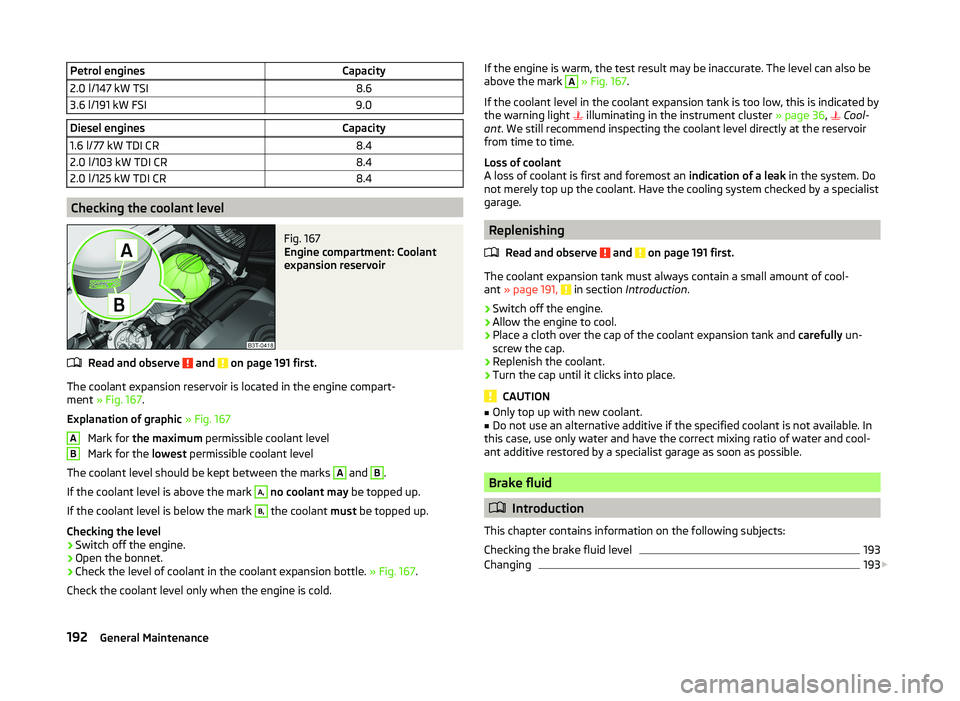
Petrol enginesCapacity2.0 l/147 kW TSI8.63.6 l/191 kW FSI9.0Diesel enginesCapacity1.6 l/77 kW TDI CR8.42.0 l/103 kW TDI CR8.42.0 l/125 kW TDI CR8.4
Checking the coolant level
Fig. 167
Engine compartment: Coolant
expansion reservoir
Read and observe and on page 191 first.
The coolant expansion reservoir is located in the engine compart-
ment » Fig. 167 .
Explanation of graphic » Fig. 167
Mark for the maximum permissible coolant level
Mark for the lowest permissible coolant level
The coolant level should be kept between the marks
A
and
B
.
If the coolant level is above the mark
A,
no coolant may be topped up.
If the coolant level is below the mark
B,
the coolant must be topped up.
Checking the level
›
Switch off the engine.
›
Open the bonnet.
›
Check the level of coolant in the coolant expansion bottle. » Fig. 167.
Check the coolant level only when the engine is cold.
ABIf the engine is warm, the test result may be inaccurate. The level can also be
above the mark A » Fig. 167 .
If the coolant level in the coolant expansion tank is too low, this is indicated by
the warning light
illuminating in the instrument cluster » page 36,
Cool-
ant . We still recommend inspecting the coolant level directly at the reservoir
from time to time.
Loss of coolant
A loss of coolant is first and foremost an indication of a leak in the system. Do
not merely top up the coolant. Have the cooling system checked by a specialist
garage.
Replenishing
Read and observe
and on page 191 first.
The coolant expansion tank must always contain a small amount of cool-
ant » page 191, in section Introduction .
›
Switch off the engine.
›
Allow the engine to cool.
›
Place a cloth over the cap of the coolant expansion tank and carefully un-
screw the cap.
›
Replenish the coolant.
›
Turn the cap until it clicks into place.
CAUTION
■ Only top up with new coolant.■Do not use an alternative additive if the specified coolant is not available. In
this case, use only water and have the correct mixing ratio of water and cool-
ant additive restored by a specialist garage as soon as possible.
Brake fluid
Introduction
This chapter contains information on the following subjects:
Checking the brake fluid level
193
Changing
193
192General Maintenance
Page 196 of 252

WARNING■The engine compartment of your car is a hazardous area. The following
warning instructions must be followed at all times when working in the en-
gine compartment » page 186.■
Do not continue your journey if the fluid level has fallen below the MIN
marking » Fig. 168 on page 193 - there is a risk of an accident. Seek help
from a specialist garage.
■
Do not use used brake fluid - the function of the brake system may be im-
paired – risk of accident!
CAUTION
Brake fluid damages the paintwork of the vehicle.
Note
■ The brake fluid is changed as part of a compulsory inspection service.■We recommend using brake fluids from the ŠKODA Original Accessories
range.
Checking the brake fluid level
Fig. 168
Engine compartment: Brake fluid
reservoir
Read and observe and on page 193 first.
The brake fluid reservoir is located in the engine compartment » Fig. 168.
›
Switch off the engine.
›
Open the bonnet.
›
Check the level of brake fluid in the reservoir » Fig. 168.
The level must be between the “MIN” and “MAX” markings.
A slight drop in the fluid level results in operation due to normal wear-and-tear
and the automatic adjustment of the brake pads.
There may be an indication of a leak in the brake system, however, if the fluid
level drops significantly within a short time or if it drops below the “MIN” mark- ing.
If the brake fluid level is too low, this is indicated by the warning light
» page 35 ,
Brake system illuminating in the instrument cluster.
Changing
Read and observe
and on page 193 first.
Brake fluid absorbs moisture. Over time it therefore absorbs moisture from the
environment.
Excessive water in the brake fluid may be the cause of corrosion in the brake
system.
The water content lowers the boiling point of the brake fluid.
The brake fluid must comply with the following standards or specifications: › VW 50114;
› FMVSS 116 DOT4.
Vehicle battery
Introduction
This chapter contains information on the following subjects:
Open cover
195
Checking the battery electrolyte level
195
Charging
196
Replacing
196
Disconnecting or reconnecting
196
Automatic load deactivation
197
Warning symbols on the vehicle battery
SymbolMeaningAlways wear eye protection.Battery acid is severely caustic. Always wear gloves and eye pro-
tection. 193Inspecting and replenishing