2011 Seat Leon 5D technical specifications
[x] Cancel search: technical specificationsPage 53 of 302

51
Child safety
Securing child seats
Ways to secure a child seat
A child seat can be secured differently on the rear seat and
on the front passenger seat. You can secure a child seat to the rear seat or front passenger seat in the
following ways:
● Child seats in groups 0 to 3 can be secured with a seat belt.
● Child seats in groups 0, 0+ and 1 with the ISOFIX and Top Tether* sys-
tems can be secured without using the seatbelt, thanks to the ISOFIX and
Top Tether* securing rings ⇒ page 51.
CategoryWeightSeat locationsFront passen-
gerRear outerRear centre
Group 0<10 kgU*U/LUGroup 0+<13 kgU*U/LUGroup 19-18 kgU*U/LUGroup 2 / 315-36 kgU*UU
Suitable for universal approved restraining systems for use in this age
category (universal retention systems are those fitted using the adult
seat belt).
Move the front passenger seat as far back as possible, as high as pos-
sible and always deactivate the airbag.
Suitable for retention systems using the ISOFIX and Top Tether* an-
chors.
U:
*:
L:
WARNING
● When travelling, children must be secured in the vehicle with a re-
straint system suitable for age, weight and size.
● Never install a child seat facing backwards on the front passenger
seat unless the front passenger airbag has been disabled. This could
cause fatal injuries to the child! However, if, in exceptional cases, it is
necessary to transport a child in the front passenger seat, the front pas-
senger airbag ⇒ page 44, Deactivating airbags* must always be disabled
and the seat adjusted to its highest position, where possible.
● Read and always observe information and warnings concerning the
use of child seats ⇒ page 46.
Child seats fastened with the “ISOFIX” and Top Tether*
system
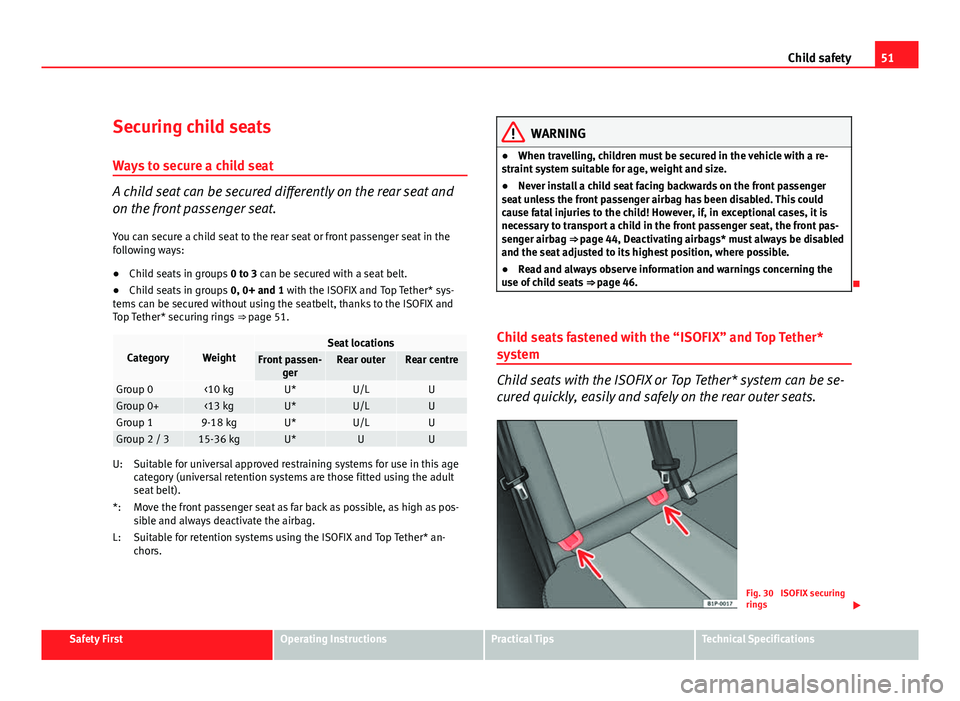
Child seats with the ISOFIX or Top Tether* system can be se-
cured quickly, easily and safely on the rear outer seats.
Fig. 30 ISOFIX securing
rings
Safety FirstOperating InstructionsPractical TipsTechnical Specifications
Page 55 of 302

53
Child safety
Safety FirstOperating InstructionsPractical TipsTechnical Specifications
Page 57 of 302

55
Cockpit
Operating Instructions Cockpit
Overview Overview of the dash panel
This overview will help you to familiarise yourself with the
controls and displays. Door release lever
Light switch . . . . . . . . . . . . . . . . . . . . . . . . . . . . . . . . . . . . . . . . . . . . . . . 115
Lighting control for instrument and control lighting . . . . . . . . .119
Headlight range control . . . . . . . . . . . . . . . . . . . . . . . . . . . . . . . . . . . 119
Air vent
Turn signal and main beam lever and cruise control system* 122, 178
Controls on the steering wheel . . . . . . . . . . . . . . . . . . . . . . . . . . . . . 91
Instrument panel:
– Instruments . . . . . . . . . . . . . . . . . . . . . . . . . . . . . . . . . . . . . . . . . . . . 57
– Display . . . . . . . . . . . . . . . . . . . . . . . . . . . . . . . . . . . . . . . . . . . . . . . . 61
– Indicator lamps . . . . . . . . . . . . . . . . . . . . . . . . . . . . . . . . . . . . . . . . . 77
Horn (works only when the ignition is on)/ Driver front airbag . .30
Windscreen wiper and washer lever and operation of the
multifunction display* . . . . . . . . . . . . . . . . . . . . . . . . . . . . . . . . . . . . . 125, 63
Left seat heating button . . . . . . . . . . . . . . . . . . . . . . . . . . . . . . . . . . . 136
1
2345678
910
11
Controls for
–
Heating* and ventilation . . . . . . . . . . . . . . . . . . . . . . . . . . . . . . . . 145
– Climatic* . . . . . . . . . . . . . . . . . . . . . . . . . . . . . . . . . . . . . . . . . . . . . . . 147
– Climatronic* . . . . . . . . . . . . . . . . . . . . . . . . . . . . . . . . . . . . . . . . . . . . 151
Radio/Navigator*
Right seat heating button . . . . . . . . . . . . . . . . . . . . . . . . . . . . . . . . . . 136
Front passenger airbag . . . . . . . . . . . . . . . . . . . . . . . . . . . . . . . . . . . . 30
Glove compartment lever . . . . . . . . . . . . . . . . . . . . . . . . . . . . . . . . . . 138
Cup holder compartment . . . . . . . . . . . . . . . . . . . . . . . . . . . . . . . . . . 139
Selector lever . . . . . . . . . . . . . . . . . . . . . . . . . . . . . . . . . . . . . . . . . . . . . 168
Controls on the centre console:
– Central locking . . . . . . . . . . . . . . . . . . . . . . . . . . . . . . . . . . . . . . . . . 97
– ESC (ESP) . . . . . . . . . . . . . . . . . . . . . . . . . . . . . . . . . . . . . . . . . . . . . . 184
– Tyre pressure monitoring
– Park Pilot* . . . . . . . . . . . . . . . . . . . . . . . . . . . . . . . . . . . . . . . . . . . . . 175
– Cigarette lighter / Power socket . . . . . . . . . . . . . . . . . . . . . . . . . 140
– Exterior mirror adjustment . . . . . . . . . . . . . . . . . . . . . . . . . . . . . . 130
– Start-Stop* . . . . . . . . . . . . . . . . . . . . . . . . . . . . . . . . . . . . . . . . . . . . . 164
Handbrake . . . . . . . . . . . . . . . . . . . . . . . . . . . . . . . . . . . . . . . . . . . . . . . . 173
Hazard warning light switch . . . . . . . . . . . . . . . . . . . . . . . . . . . . . . . 120
Warning lamp for deactivated front passenger airbag . . . . . . .44
Pedals
Ignition lock . . . . . . . . . . . . . . . . . . . . . . . . . . . . . . . . . . . . . . . . . . . . . . 159
Steering column control lever* . . . . . . . . . . . . . . . . . . . . . . . . . . . . . 157
12
13141516171819
202122232425
Safety FirstOperating InstructionsPractical TipsTechnical Specifications
Page 59 of 302

57
Cockpit
Instruments Instrument overview
The instruments display the vehicle operating status.
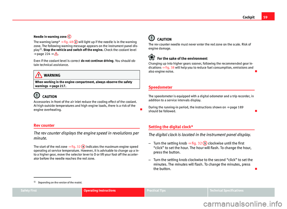
Fig. 32 Detailed view of the dash panel: instrument
panel
Detailed view of the dash panel: instrument panel Fuel gauge ⇒ page 58
Multifunction display ⇒ page 61
Engine coolant temperature gauge ⇒ page 58
Rev counter ⇒ page 59
Time adjustment button / trip recorder reset button ⇒ page 59
Speedometer ⇒ page 59
1
23456
Safety FirstOperating InstructionsPractical TipsTechnical Specifications
Page 61 of 302

59
Cockpit
Needle in warning zone C
The warning lamp* ⇒ fig. 48 2 will light up if the needle is in the warning
zone. The following warning message appears on the instrument panel dis-
play 1)
. Stop the vehicle and switch off the engine. Check the coolant level
⇒ page 224 ⇒
.
Even if the coolant level is correct do not continue driving. You should ob-
tain technical assistance.
WARNING
When working in the engine compartment, always observe the safety
warnings ⇒ page 217.
CAUTION
Accessories in front of the air inlet reduce the cooling effect of the coolant.
At high outside temperatures and high engine loads, there is a risk of the
engine overheating.
Rev counter
The rev counter displays the engine speed in revolutions per
minute. The start of the red zone ⇒ fig. 32 4
indicates the maximum engine speed
operating at service temperature. However, it is advisable to change up a in-
to a higher gear, move the selector lever to D or lift your foot off the acceler-
ator before the needle reaches the red zone.
CAUTION
The rev counter needle must never enter the red zone on the scale. Risk of
engine damage.
For the sake of the environment
Changing up into higher gears sooner, following the recommended gear in-
dications ⇒ fig. 38 will help you to reduce fuel consumption, emissions and
also engine noise.
Speedometer
The speedometer is equipped with a digital odometer and a trip recorder, in
addition to a service intervals display.
During the running-in period, the instructions shown on ⇒ page 189
should be followed.
Setting the digital clock*
The digital clock is located in the instrument panel display.
– Turn the setting knob ⇒ fig. 32 5
clockwise until the first
“click” to set the hour. The hour will flash. To change the hour,
press the button.
– Turn the setting knob clockwise to the second “click” to set the
minutes. The minutes will flash. To change the minutes, press
the button.
1)
Depending on the version of the model.
Safety FirstOperating InstructionsPractical TipsTechnical Specifications
Page 63 of 302

61
Cockpit
Digital instrument panel display
Display (without warning or information texts)
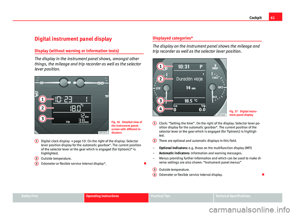
The display in the instrument panel shows, amongst other
things, the mileage and trip recorder as well as the selector
lever position.
Fig. 36 Detailed view of
the instrument panel:
screen with different in-
dicators
Digital clock display ⇒ page 59. On the right of the display: Selector
lever position display for the automatic gearbox*. The current position
of the selector lever or the gear which is engaged (for tiptronic)* is
highlighted.
Outside temperature.
Odometer or flexible service interval display*.
1
23
Displayed categories*
The display on the instrument panel shows the mileage and
trip recorder as well as the selector lever position.
Fig. 37 Digital instru-
ment panel display
Clock: “Setting the time”. On the right of the display: Selector lever po-
sition display for the automatic gearbox*. The current position of the
selector lever or the gear which is engaged (for Tiptronic) is highligh-
ted.
There are optional and automatic displays in this field.
Optional indicators: e.g. those on the multifunction display (MFI)
Automatic indicators: Information and warning messages.
Menus providing further information and which can be used to make di-
verse settings are also shown: “Instrument panel menus”
Outside temperature.
Odometer or flexible service interval display.
1
2
–
–
–
3
4
Safety FirstOperating InstructionsPractical TipsTechnical Specifications
Page 65 of 302

63
Cockpit
Indications for vehicles with LongLife service
Technical progress has made it possible to considerably reduce servicing re-
quirements. With the LongLife System, SEAT ensures that your vehicle only
has an interval service when it is necessary. The length of the service inter-
vals (max. two years) is determined by factors such as conditions under
which the vehicle is used and personal driving style.
The service pre-warning will first appear 20 days before the date on which
the service is due. The distance travelled is rounded off to the nearest 100
km and the time to full days. The current service message can only be con-
sulted 500 km after the last service. Until that time, only dashes are dis-
played.
Note
● If you reset the display manually, the next service interval will be indica-
ted after 15 000 km or one year and will not be calculated individually.
● Do not reset the display between service intervals as the display will
otherwise be incorrect.
● In LongLife Service vehicles, if the battery is disconnected for a long pe-
riod, the days remaining until the next service cannot be calculated. There-
fore, the service message displays on the instrument panel may be incor-
rect. Take into account the maximum authorised service intervals. Multifunction display (MFI)*
The multifunction display (MFI) shows you information on
the journey and fuel consumption.
Fig. 39 Rocker buttons A
and B. Steering wheel
controls.
Fig. 40 Digital instru-
ment panel display
Safety FirstOperating InstructionsPractical TipsTechnical Specifications
Page 67 of 302

65
Cockpit
Memory displays
● Driving speed
● Journey duration
● Average speed
● Distance
● Distance to empty
● Average fuel consumption
● Current fuel consumption
● Outside temperature display
● Speed warning
Km/h - Driving speed
Driving speed is digitally shown in the display.
min - Journey duration
The display shows the amount of time which has elapsed since the ignition
was switched on.
The maximum display value in both memories is 19 hours and 59 minutes.
The memory will automatically be deleted once this value has been
reached.
Ø mph - Average speed The average speed will be shown after running a distance of approximately
100 metres. Until then dashes will appear in the display. The display will be
updated every 5 seconds while the vehicle is in motion.
km - Distance travelled
The display shows the distance travelled since the ignition was switched on. The maximum display value in both memories is 1999 km. The memory will
automatically be deleted once this value has been reached.
Km - Fuel range
The fuel range is calculated using the figures for tank content and current
fuel consumption. It shows how far the vehicle can travel using the same
conditions as a reference.
Ø ltr/100km - Average fuel consumption
The average fuel consumption will be shown ⇒ fig. 42 after a distance of ap-
proximately 100 metres has been travelled. Until then dashes will appear in
the display. The display will be updated every 5 seconds while the vehicle is
in motion. The amount of fuel used will not be shown.
l/100 km or l/h - Current fuel consumptionThe display will show the current fuel consumption in litre/km whilst the ve-
hicle is in motion or in litre/hour when the vehicle is in a stationary position
with the engine running.
Using this display you can see how your driving style affects fuel consump-
tion ⇒ page 191.
Outside temperature display
The measurement range extends from -45°C to +58°C. At temperatures be-
low +4°C, an ice crystal symbol is displayed and a warning sounds if the ve-
hicle is moving at more than 20 km/h (ice danger warning). This symbol will
flash for about 10 seconds and remains lit until the outside temperature
rises above +4°C or 6°C if it was already lit.
Set speed indicator
When driving at the required speed, enter the speed indicator mode and
press the button A
(Reset), the display remembers the indicated speed. If
the indicated speed is exceeded, a warning message is displayed on the
screen 1)
and an acoustic signal is given.
1)
Depending on the model version, the message on the screen may vary and may be repre-
sented by flashing of the speed indication or by a speed message.
Safety FirstOperating InstructionsPractical TipsTechnical Specifications