2011 RENAULT SCENIC relay
[x] Cancel search: relayPage 109 of 365

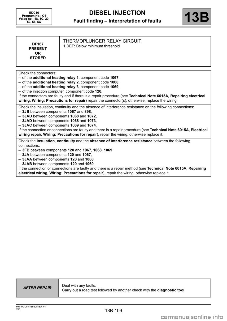
13B-109
MR-372-J84-13B200$324.mif
V13
DIESEL INJECTION
Fault finding – Interpretation of faults
EDC16
Program No.: C1
Vdiag no.: 18, 1C, 20,
50, 58, 5C
13B
DF167
PRESENT
OR
STOREDTHERMOPLUNGER RELAY CIRCUIT
1.DEF: Below minimum threshold
Check the connectors:
– of the additional heating relay 1, component code 1067,
– of the additional heating relay 2, component code 1068,
– of the additional heating relay 3, component code 1069,
– of the injection computer, component code 120.
If the connectors are faulty and if there is a repair procedure (see Technical Note 6015A, Repairing electrical
wiring, Wiring: Precautions for repair) repair the connector(s); otherwise, replace the wiring.
Check the insulation, continuity and the absence of interference resistance on the following connections:
–3JB between components 1067 and 898,
–3JAD between components 1068 and 1072,
–3JAD between components 1068 and 1073,
–3JAC between components 1069 and 1074.
If the connection or connections are faulty and there is a repair procedure (see Technical Note 6015A, Electrical
wiring repair, Wiring: Precautions for repair), repair the wiring, otherwise replace it.
Check the insulation, continuity and the absence of interference resistance between the following
connections:
–3FB between components 120 and 1067, 1068, 1069
–3JA between components 120 and 1067,
–3JAA between components 120 and 1068,
–3JAB between components 120 and 1069,
If the connection or connections are faulty and there is a repair method (see Technical Note 6015A, Repairing
electrical wiring, Wiring: Precautions for repair
), repair the wiring, otherwise replace it.
AFTER REPAIRDeal with any faults.
Carry out a road test followed by another check with the diagnostic tool.
Page 110 of 365

13B-110
MR-372-J84-13B200$324.mif
V13
13B
DIESEL INJECTION
Fault finding – Interpretation of faults
DF176
PRESENT
OR
STOREDLOW-SPEED FAN ASSEMBLY CIRCUIT
CO: Open circuit
CC.0: Short circuit to earth
CC.1: Short circuit to + 12 V
1.DEF: Inconsistent signal
NOTESConditions for applying the fault finding procedure to a stored fault:
The fault is declared present after:
– an attempted start, or with engine running,
– command AC038 Low-speed fan assembly relay is run.
Special notes:
Use bornier Elé.1681 or Elé.1590 for any operation on the injection computer
connectors.
CO
NOTESNone.
Check the + 12 V after relay supply to the relay mounting R09 on connection 3FB.
Check the condition of the connections and the correct operation of the running lights relay.R09
Replace it if necessary.
Check the continuity and absence of interference resistance on connection 3JN between components 120
and 597.
If the connection is faulty and there is a repair procedure (see Technical Note 6015A, Electrical wiring repair,
Wiring: Precautions for repair), repair the wiring, otherwise replace it.
CC.0
NOTESNone.
Check the continuity and insulation to earth of connection 3FB between components 983 and 700.
If the connection is faulty and there is a repair procedure (see Technical Note 6015A, Electrical wiring repair,
Wiring: Precautions for repair), repair the wiring, otherwise replace it.
AFTER REPAIRDeal with any faults.
Carry out a road test followed by another check with the diagnostic tool.
EDC16_V18_DF176/EDC16_V1C_DF176/EDC16_V20_DF176EDC16
Program No.: C1
Vdiag no.: 18, 1C, 20
Page 111 of 365

13B-111
MR-372-J84-13B200$324.mif
V13
DIESEL INJECTION
Fault finding – Interpretation of faults
EDC16
Program No.: C1
Vdiag no.: 18, 1C, 20
13B
DF176
CONTINUED
CC.1
NOTESNone.
Check the continuity and insulation from + 12 V of connection 3JN between components 597 and 120.
If the connection is faulty and there is a repair procedure (see Technical Note 6015A, Electrical wiring repair,
Wiring: Precautions for repair), repair the wiring, otherwise replace it.
1. DEF
NOTESNone.
Check the condition of the connections:
– on the low-speed fan unit relay connector,
– on the injection computer grey connector C.
Repair if necessary.
Check the continuity and absence of interference resistance between the following connections:
– connection code 3JN between components 120 and 597.
– connection code 3FB between components 983 and 700.
If the connection or connections are faulty and there is a repair method (see Technical Note 6015A, Repairing
electrical wiring, Wiring: Precautions for repair), repair the wiring, otherwise replace it.
AFTER REPAIRDeal with any faults.
Carry out a road test followed by another check with the diagnostic tool.
Page 112 of 365

13B-112
MR-372-J84-13B200$324.mif
V13
DIESEL INJECTION
Fault finding – Interpretation of faults
EDC16
Program No.: C1
Vdiag no.: 18, 1C, 20
13B
DF177
PRESENT
OR
STOREDHIGH-SPEED FAN ASSEMBLY CIRCUIT
CO: Open circuit
CC.0: Short circuit to earth
CC.1: Short circuit to + 12 V
1.DEF: Inconsistent signal
NOTESConditions for applying the fault finding procedure to a stored fault:
The fault is declared present after:
– an attempted start, or with engine running,
– command AC039 High-speed fan unit run.
Special notes:
Use bornier Elé. 1681 for all operations on the injection computer connectors.
CO
NOTESNone.
Check the + 12 V after relay supply to the fan assembly relay mounting R10 on connection 3FB.
Check the condition of the connections and the correct operation of the relay.R10
Replace the relay if necessary.
Check the continuity and the absence of interference resistance of connection 3JP between components 120
and 597.
If the connection is faulty and there is a repair procedure (see Technical Note 6015A, Electrical wiring repair,
Wiring: Precautions for repair), repair the wiring, otherwise replace it.
CC.0
NOTESNone.
Check the continuity and insulation to earth of connection 3FB between components 120 and 983.
If the connection is faulty and there is a repair procedure (see Technical Note 6015A, Electrical wiring repair,
Wiring: Precautions for repair), repair the wiring, otherwise replace it.
AFTER REPAIRDeal with any faults.
Carry out a road test followed by another check with the diagnostic tool.
EDC16_V18_DF177/EDC16_V1C_DF177/EDC16_V20_DF177
Page 113 of 365

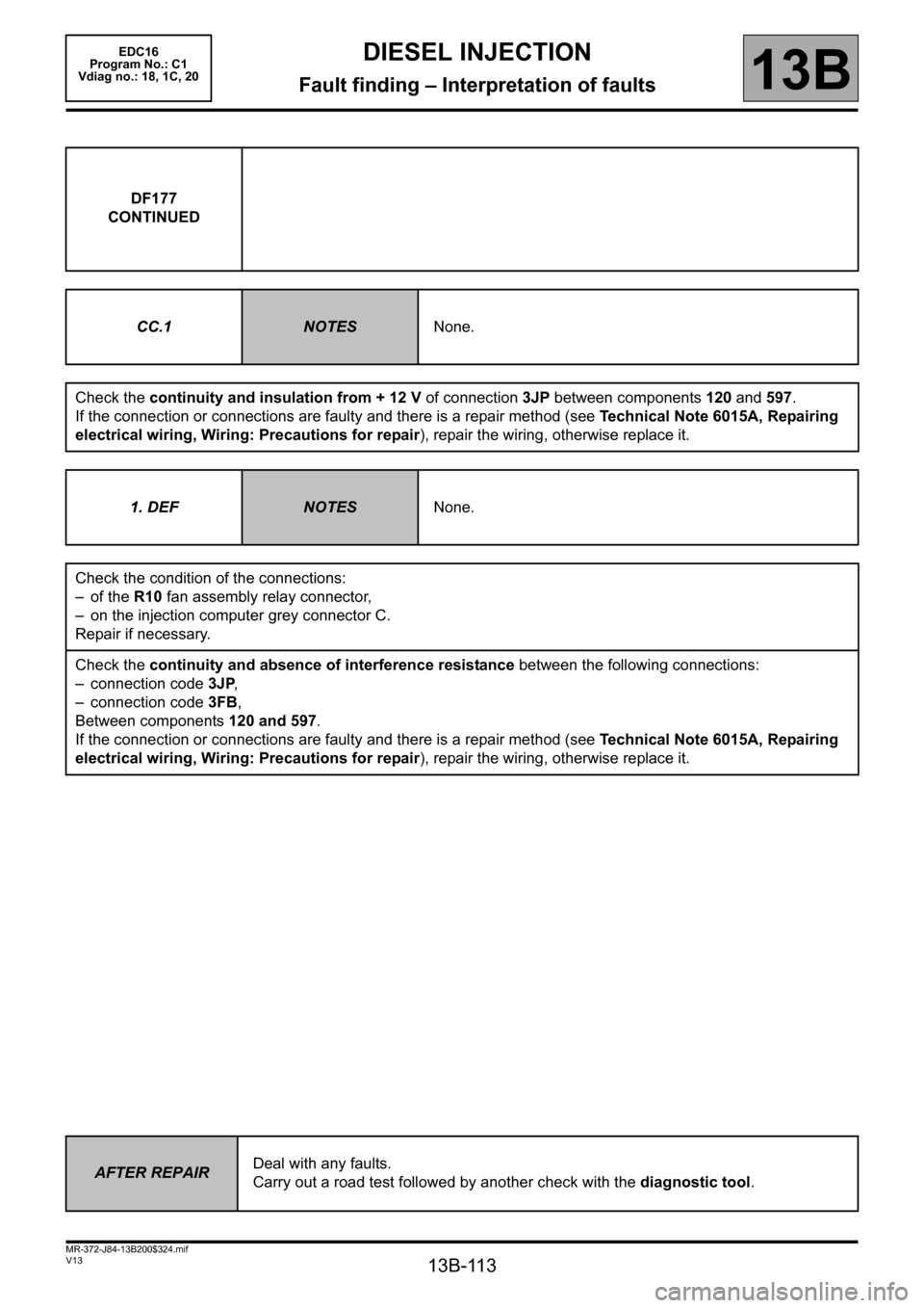
13B-113
MR-372-J84-13B200$324.mif
V13
DIESEL INJECTION
Fault finding – Interpretation of faults
EDC16
Program No.: C1
Vdiag no.: 18, 1C, 20
13B
DF177
CONTINUED
CC.1
NOTESNone.
Check the continuity and insulation from + 12 V of connection 3JP between components 120 and 597.
If the connection or connections are faulty and there is a repair method (see Technical Note 6015A, Repairing
electrical wiring, Wiring: Precautions for repair), repair the wiring, otherwise replace it.
1. DEF
NOTESNone.
Check the condition of the connections:
– of the R10 fan assembly relay connector,
– on the injection computer grey connector C.
Repair if necessary.
Check the continuity and absence of interference resistance between the following connections:
– connection code 3JP,
– connection code 3FB,
Between components 120 and 597.
If the connection or connections are faulty and there is a repair method (see Technical Note 6015A, Repairing
electrical wiring, Wiring: Precautions for repair), repair the wiring, otherwise replace it.
AFTER REPAIRDeal with any faults.
Carry out a road test followed by another check with the diagnostic tool.
Page 121 of 365

13B-121
MR-372-J84-13B200$324.mif
V13
13B
DIESEL INJECTION
Fault finding – Interpretation of faults
DF238
PRESENT
OR
STOREDTHERMOPLUNGER NO.3 RELAY CIRCUIT
CO: Open circuit
CC.0: Short circuit to earth
CC.1: Short circuit to + 12 V
1.DEF: Inconsistent signal
NOTESConditions for applying the fault finding procedure to stored faults:
The fault is displayed as present following an engine start or following actuator
command AC031 Thermoplunger relay no. 3.
If faults DF239 “Thermoplunger relay No. 2 circuit” and DF240 “Thermoplunger
relay No. 1 circuit” occur, ignore them and go directly to configuration CF030
“Thermoplunger configuration”.
Special notes:
Use bornier Elé. 1681 for any work on the computer connectors.
See the Wiring diagrams Technical Note for the vehicle to locate the fuses and
relays concerned.
1.DEF
CO
NOTESNone
Check for + 12 V after ignition feed on relay mounting R5, component code 1069 on connection 3FB.
If there is no + 12 V supply, refer to the interpretation of fault DF015 Main relay control circuit.
Check the condition of the connectors of thermoplunger no.3 relay (R5) and of the injection computer.
Repair if necessary.
Check the condition and correct operation of relay R5, component code 1069.
Replace if defective.
Check the continuity and absence of interference resistance on connection 3JAB between components 120
and 597.
If the connection or connections are faulty and there is a repair method (see Technical Note 6015A, Repairing
electrical wiring, Wiring: Precautions for repair), repair the wiring, otherwise replace it.
AFTER REPAIRDeal with any faults.
Carry out a road test followed by another check with the diagnostic tool.
EDC16_V18_DF238/EDC16_V1C_DF238/EDC16_V20_DF238EDC16
Program No.: C1
Vdiag no.: 18, 1C, 20
Page 122 of 365

13B-122
MR-372-J84-13B200$324.mif
V13
DIESEL INJECTION
Fault finding – Interpretation of faults
EDC16
Program No.: C1
Vdiag no.: 18, 1C, 20
13B
DF238
CONTINUED 1
CC.0
NOTESNone
Check the condition and correct operation of relay R5, component code 1069.
Replace if defective.
Check the continuity, absence of interference resistance and insulation to earth of connection 3FB between
components 1069 and 983.
If the connection or connections are faulty and there is a repair method (see Technical Note 6015A, Repairing
electrical wiring, Wiring: Precautions for repair), repair the wiring, otherwise replace it.
CC.1
NOTESNone.
Check the condition and correct operation of relay R5, component code 1069.
Replace if defective.
Check the continuity and insulation from + 12 V of connection 3JAB between components 597 and 120.
If the connection or connections are faulty and there is a repair method (see Technical Note 6015A, Repairing
electrical wiring, Wiring: Precautions for repair), repair the wiring, otherwise replace it.
AFTER REPAIRDeal with any faults.
Carry out a road test followed by another check with the diagnostic tool.
Page 123 of 365

13B-123
MR-372-J84-13B200$324.mif
V13
DIESEL INJECTION
Fault finding – Interpretation of faults
EDC16
Program No.: C1
Vdiag no.: 18, 1C, 20
13B
DF239
PRESENT
OR
STOREDTHERMOPLUNGER RELAY CIRCUIT N° 2
CO: Open circuit
CC.0: Short circuit to earth
CC.1: Short circuit to + 12 V
1.DEF: Inconsistent signal
NOTESConditions for applying the fault finding procedure to stored faults:
The fault appears after an engine start or actuator command AC064 Thermoplunger
no. 2 relay.
If faults DF238 “Thermoplunger relay No. 3 circuit” and DF240 “Thermoplunger
relay No. 1 circuit” occur, ignore them and go directly to configuration CF030
“Thermoplunger configuration”.
Special notes:
Use bornier Elé. 1681 for any work on the computer connectors.
See the Wiring diagrams Technical Note for the vehicle to locate the fuses and
relays concerned.
1.DEF
CO
NOTESNone
Check for + 12 V after ignition feed on relay mounting R11, component code 1068 on connection 3FB.
If there is no + 12 V supply, refer to the interpretation of fault DF015 Main relay control circuit.
Check the condition of the connectors on thermoplunger no. 2 relay (R11) and on the injection computer.
Repair if necessary.
Check the condition and correct operation of relay R11, component code 1068.
Replace if defective.
Check the continuity and absence of interference resistance on connection 3JAA between components 120
and 597.
If the connection or connections are faulty and there is a repair method (see Technical Note 6015A, Repairing
electrical wiring, Wiring: Precautions for repair), repair the wiring, otherwise replace it.
AFTER REPAIRDeal with any faults.
Carry out a road test followed by another check with the diagnostic tool.
EDC16_V18_DF239/EDC16_V1C_DF239/EDC16_V20_DF239