Page 163 of 356

9
i
161
DRIVING
SPEED LIMITER
System which prevents the vehicle from
exceeding the speed programmed by
the driver.
When the programmed speed limit is
reached, pressing the accelerator pedal
no longer has any effect.
The controls of this system are grouped
together on stalk A
.
1.
Speed limiter mode selection dial
2.
Value decrease button
3.
Value increase button
4.
Speed limiter on/off button
The programmed information is grouped
together on the instrument panel screen.
5.
Speed limiter on/off indication
6.
Speed limiter mode selection indication
7.
Programmed speed value
Steering mounted controls
Displays in the instrument panel
The speed limiter cannot, in any cir-
cumstances, replace the need to re-
spect speed limits, nor can it replace
the need for vigilance and responsi-
bility on the part of the driver. The speed limiter is switched on
man-
ually: it requires a programmed speed
of at least 20 mph (30 km/h).
The speed limiter is switched off
by
manual operation of the control.
The programmed speed can be ex-
ceeded temporarily by pressing the ac-
celerator fi rmly.
To return to the programmed speed,
simply slow down to a speed below the
programmed speed.
The programmed speed remains in the
memory when the ignition is switched off.
Page 165 of 356
9
i
163
DRIVING
CRUISE CONTROL
System which automatically maintains
the speed of the vehicle at the value
programmed by the driver, without any
action on the accelerator pedal.
The cruise control is switched on
manu-
ally: it requires a minimum vehicle speed
of 25 mph (40 km/h) and the engaging:
- of fourth gear on the manual gearbox,
- of second gear on the electronic
gear control gearbox or automatic
gearbox, in sequential driving mode,
- of position A
on the electronic gear
control gearbox or D
on the auto-
matic gearbox.
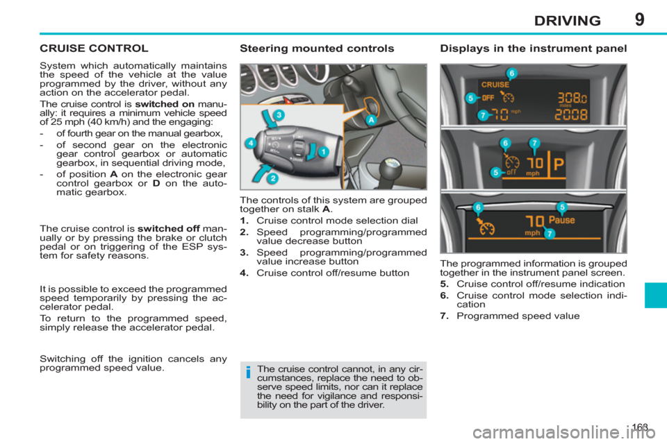
The controls of this system are grouped
together on stalk A
.
1.
Cruise control mode selection dial
2.
Speed programming/programmed
value decrease button
3.
Speed programming/programmed
value increase button
4.
Cruise control off/resume button The programmed information is grouped
together in the instrument panel screen.
5.
Cruise control off/resume indication
6.
Cruise control mode selection indi-
cation
7.
Programmed speed value
Steering mounted controls
Displays in the instrument panel
The cruise control cannot, in any cir-
cumstances, replace the need to ob-
serve speed limits, nor can it replace
the need for vigilance and responsi-
bility on the part of the driver. The cruise control is switched off
man-
ually or by pressing the brake or clutch
pedal or on triggering of the ESP sys-
tem for safety reasons.
It is possible to exceed the programmed
speed temporarily by pressing the ac-
celerator pedal.
To return to the programmed speed,
simply release the accelerator pedal.
Switching off the ignition cancels any
programmed speed value.
Page 172 of 356
10
170
CHECKS
PETROL ENGINES
The various caps and covers allow access for checking the levels of the various fl uids and for replacing certain components.
1.
Power steering reservoir.
2.
Screenwash and headlamp wash
reservoir.
3.
Coolant reservoir.
4.
Brake fl uid reservoir.
5.
Battery/Fuses.
6.
Fusebox.
7.
Air fi lter.
8.
Engine oil dipstick.
9.
Engine oil fi ller cap.
Page 173 of 356
10
171
CHECKS
DIESEL ENGINES
The various caps and covers allow access for checking the levels of the various fl uids, for replacing certain components and
for priming the fuel system.
1.
Power steering reservoir.
2.
Screenwash and headlamp wash
reservoir.
3.
Coolant reservoir.
4.
Brake fl uid reservoir.
5.
Battery/Fuses.
6.
Fusebox.
7.
Air fi lter.
8.
Engine oil dipstick.
9.
Engine oil fi ller cap.
10.
Priming pump * .
11 .
Bleed screw * .
* According to engine.
Page 174 of 356
10
!
i
172
CHECKS
CHECKING LEVELS
Check all of these levels regularly and
top them up if necessary, unless other-
wise indicated.
If a level drops signifi cantly, have the
corresponding system checked by a
PEUGEOT dealer or a qualifi ed work-
shop.
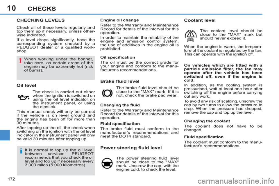
Brake fluid level
On vehicles which are fi tted with a
particle emission fi lter, the fan may
operate after the vehicle has been
switched off, even if the engine is
cold.
In addition, as the cooling system is
pressurised, wait at least one hour after
switching off the engine before carrying
out any work.
To avoid any risk of scalding, unscrew the
cap by two turns to allow the pressure to
drop. When the pressure has dropped,
remove the cap and top up the level.
Oil level
The check is carried out either
when the ignition is switched on
using the oil level indicator on
the instrument panel, or using
the dipstick.
This manual check will only be correct
if the vehicle is on level ground and
the engine has been off for more than
30 minutes.
After topping up the oil, the check when
switching on the ignition with the oil level
indicator in the instrument panel will only
be valid 30 minutes after topping up. The brake fl uid level should be
close to the "MAX" mark. If it is
not, check the brake pad wear.
Changing the fl uid
Refer to the Warranty and Maintenance
Record for details of the interval for this
operation.
Power steering fluid level
The power steering fl uid level
should be close to the "MAX"
mark. Unscrew the cap, with the
engine cold, to check the level.
Engine oil change
Refer to the Warranty and Maintenance
Record for details of the interval for this
operation.
In order to maintain the reliability of the
engine and emission control system,
the use of additives in the engine oil is
prohibited.
It is normal to top up the oil level
between services. PEUGEOT
recommends that you check the oil
level and top up if necessary every
3 000 miles (5 000 kilometres).
Fluid specifi cation
The brake fl uid must conform to the
manufacturer's recommendations and
meet the DOT4 standard.
Changing the coolant
The coolant does not have to be
changed.
Coolant level
The coolant level should be
close to the "MAX" mark but
should never exceed it.
When the engine is warm, the tempera-
ture of the coolant is regulated by the fan.
This can operate with the ignition off.
Fluid specifi cation
The coolant must conform to the manu-
facturer's recommendations.
When working under the bonnet,
take care, as certain areas of the
engine may be extremely hot (risk
of burns).
Oil specifi cation
The oil must be the correct grade for
your engine and conform to the manu-
facturer's recommendations.
Page 178 of 356
11
i
176
PRACTICAL INFORMATION
The speed limit sticker I
must be
affi xed to the vehicle's steering
wheel to remind you that a wheel is
in temporary use.
Do not exceed a speed of 50 mph
(80 km/h) when driving with a tyre
repaired using this type of kit.
TEMPORARY
PUNCTURE REPAIR KIT
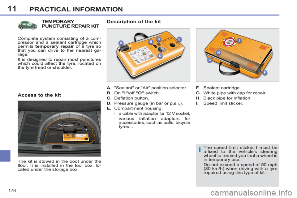
The kit is stowed in the boot under the
fl oor. It is installed in the tool box, lo-
cated under the storage box.
Description of the kit
A.
"Sealant" or "Air" position selector.
B.
On "I"
/off "O"
switch.
C.
Defl ation button.
D.
Pressure gauge (in bar or p.s.i.).
E.
Compartment housing:
- a cable with adaptor for 12 V socket,
- various infl ation adaptors for
accessories, such as balls, bicycle
tyres...
F.
Sealant cartridge.
G.
White pipe with cap for repair.
H.
Black pipe for infl ation.
I.
Speed limit sticker.
Access to the kit
Complete system consisting of a com-
pressor and a sealant cartridge which
permits temporary repair
of a tyre so
that you can drive to the nearest ga-
rage.
It is designed to repair most punctures
which could affect the tyre, located on
the tyre tread or shoulder.
Page 183 of 356
11
i
181
PRACTICAL INFORMATION
It is designed to repair holes of a
maximum diameter of 6 mm, only
where located on the tyre tread or
shoulder. Avoid removing any for-
eign bodies which have penetrated
the tyre.
TEMPORARY
PUNCTURE REPAIR
KIT
Complete system consisting of a
compressor and a bottle of sealant
which permits temporary repair
of the
tyre so that you can drive to the nearest
garage.
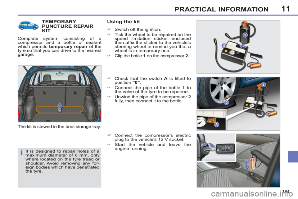
The kit is stowed in the boot storage tray.
Using the kit
�)
Switch off the ignition.
�)
Tick the wheel to be repaired on the
speed limitation sticker enclosed
then affi x the sticker to the vehicle's
steering wheel to remind you that a
wheel is in temporary use.
�)
Clip the bottle 1
on the compressor 2
.
�)
Check that the switch A
is tilted to
position "0"
.
�)
Connect the pipe of the bottle 1
to
the valve of the tyre to be repaired.
�)
Unwind the pipe of the compressor 2
fully, then connect it to the bottle.
�)
Connect the compressor's electric
plug to the vehicle's 12 V socket.
�)
Start the vehicle and leave the
engine running.
Page 201 of 356
11
199
PRACTICAL INFORMATION
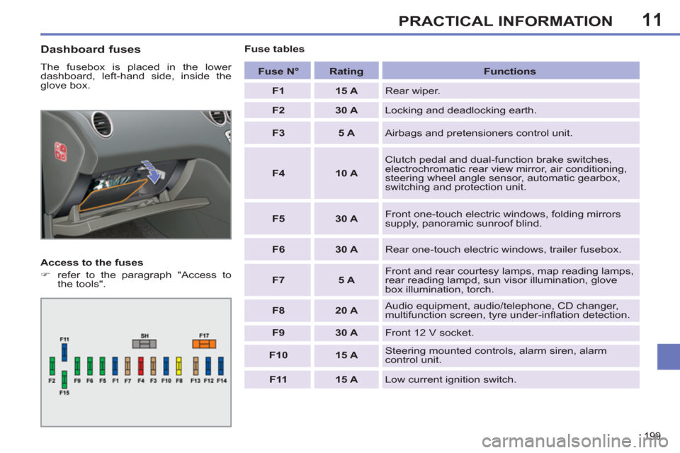
Dashboard fuses
The fusebox is placed in the lower
dashboard, left-hand side, inside the
glove box.
Access to the fuses
�)
refer to the paragraph "Access to
the tools".
Fuse tables
Fuse N°
Rating
Functions
F1
15 A
Rear wiper.
F2
30 A
Locking and deadlocking earth.
F3
5 A
Airbags and pretensioners control unit.
F4
10 A
Clutch pedal and dual-function brake switches,
electrochromatic rear view mirror, air conditioning,
steering wheel angle sensor, automatic gearbox,
switching and protection unit.
F5
30 A
Front one-touch electric windows, folding mirrors
supply, panoramic sunroof blind.
F6
30 A
Rear one-touch electric windows, trailer fusebox.
F7
5 A
Front and rear courtesy lamps, map reading lamps,
rear reading lampd, sun visor illumination, glove
box illumination, torch.
F8
20 A
Audio equipment, audio/telephone, CD changer,
multifunction screen, tyre under-infl ation detection.
F9
30 A
Front 12 V socket.
F10
15 A
Steering mounted controls, alarm siren, alarm
control unit.
F11
15 A
Low current ignition switch.